EP2029202B1 - Sicherheitsvorrichtung zur injektion eines medizinprodukts, z.b. eines lyophiliserten produkts - Google Patents
Sicherheitsvorrichtung zur injektion eines medizinprodukts, z.b. eines lyophiliserten produkts Download PDFInfo
- Publication number
- EP2029202B1 EP2029202B1 EP07788884.0A EP07788884A EP2029202B1 EP 2029202 B1 EP2029202 B1 EP 2029202B1 EP 07788884 A EP07788884 A EP 07788884A EP 2029202 B1 EP2029202 B1 EP 2029202B1
- Authority
- EP
- European Patent Office
- Prior art keywords
- injection
- locking
- locking member
- members
- syringe body
- Prior art date
- Legal status (The legal status is an assumption and is not a legal conclusion. Google has not performed a legal analysis and makes no representation as to the accuracy of the status listed.)
- Active
Links
Images




Classifications
-
- A—HUMAN NECESSITIES
- A61—MEDICAL OR VETERINARY SCIENCE; HYGIENE
- A61M—DEVICES FOR INTRODUCING MEDIA INTO, OR ONTO, THE BODY; DEVICES FOR TRANSDUCING BODY MEDIA OR FOR TAKING MEDIA FROM THE BODY; DEVICES FOR PRODUCING OR ENDING SLEEP OR STUPOR
- A61M5/00—Devices for bringing media into the body in a subcutaneous, intra-vascular or intramuscular way; Accessories therefor, e.g. filling or cleaning devices, arm-rests
- A61M5/178—Syringes
- A61M5/31—Details
- A61M5/32—Needles; Details of needles pertaining to their connection with syringe or hub; Accessories for bringing the needle into, or holding the needle on, the body; Devices for protection of needles
- A61M5/3205—Apparatus for removing or disposing of used needles or syringes, e.g. containers; Means for protection against accidental injuries from used needles
- A61M5/321—Means for protection against accidental injuries by used needles
- A61M5/3243—Means for protection against accidental injuries by used needles being axially-extensible, e.g. protective sleeves coaxially slidable on the syringe barrel
- A61M5/326—Fully automatic sleeve extension, i.e. in which triggering of the sleeve does not require a deliberate action by the user
-
- A—HUMAN NECESSITIES
- A61—MEDICAL OR VETERINARY SCIENCE; HYGIENE
- A61M—DEVICES FOR INTRODUCING MEDIA INTO, OR ONTO, THE BODY; DEVICES FOR TRANSDUCING BODY MEDIA OR FOR TAKING MEDIA FROM THE BODY; DEVICES FOR PRODUCING OR ENDING SLEEP OR STUPOR
- A61M5/00—Devices for bringing media into the body in a subcutaneous, intra-vascular or intramuscular way; Accessories therefor, e.g. filling or cleaning devices, arm-rests
- A61M5/178—Syringes
- A61M5/31—Details
- A61M5/32—Needles; Details of needles pertaining to their connection with syringe or hub; Accessories for bringing the needle into, or holding the needle on, the body; Devices for protection of needles
- A61M5/3205—Apparatus for removing or disposing of used needles or syringes, e.g. containers; Means for protection against accidental injuries from used needles
- A61M5/321—Means for protection against accidental injuries by used needles
- A61M5/3243—Means for protection against accidental injuries by used needles being axially-extensible, e.g. protective sleeves coaxially slidable on the syringe barrel
- A61M5/3245—Constructional features thereof, e.g. to improve manipulation or functioning
- A61M2005/3247—Means to impede repositioning of protection sleeve from needle covering to needle uncovering position
-
- A—HUMAN NECESSITIES
- A61—MEDICAL OR VETERINARY SCIENCE; HYGIENE
- A61M—DEVICES FOR INTRODUCING MEDIA INTO, OR ONTO, THE BODY; DEVICES FOR TRANSDUCING BODY MEDIA OR FOR TAKING MEDIA FROM THE BODY; DEVICES FOR PRODUCING OR ENDING SLEEP OR STUPOR
- A61M5/00—Devices for bringing media into the body in a subcutaneous, intra-vascular or intramuscular way; Accessories therefor, e.g. filling or cleaning devices, arm-rests
- A61M5/178—Syringes
- A61M5/31—Details
- A61M5/32—Needles; Details of needles pertaining to their connection with syringe or hub; Accessories for bringing the needle into, or holding the needle on, the body; Devices for protection of needles
- A61M5/3205—Apparatus for removing or disposing of used needles or syringes, e.g. containers; Means for protection against accidental injuries from used needles
- A61M5/321—Means for protection against accidental injuries by used needles
- A61M5/3243—Means for protection against accidental injuries by used needles being axially-extensible, e.g. protective sleeves coaxially slidable on the syringe barrel
- A61M5/326—Fully automatic sleeve extension, i.e. in which triggering of the sleeve does not require a deliberate action by the user
- A61M2005/3261—Fully automatic sleeve extension, i.e. in which triggering of the sleeve does not require a deliberate action by the user triggered by radial deflection of the anchoring parts between sleeve and syringe barrel, e.g. spreading of sleeve retaining hooks having slanted surfaces by engagement with conically shaped collet of the piston rod during the last portion of the injection stroke of the plunger
-
- A—HUMAN NECESSITIES
- A61—MEDICAL OR VETERINARY SCIENCE; HYGIENE
- A61M—DEVICES FOR INTRODUCING MEDIA INTO, OR ONTO, THE BODY; DEVICES FOR TRANSDUCING BODY MEDIA OR FOR TAKING MEDIA FROM THE BODY; DEVICES FOR PRODUCING OR ENDING SLEEP OR STUPOR
- A61M5/00—Devices for bringing media into the body in a subcutaneous, intra-vascular or intramuscular way; Accessories therefor, e.g. filling or cleaning devices, arm-rests
- A61M5/178—Syringes
- A61M5/31—Details
- A61M5/32—Needles; Details of needles pertaining to their connection with syringe or hub; Accessories for bringing the needle into, or holding the needle on, the body; Devices for protection of needles
- A61M5/3205—Apparatus for removing or disposing of used needles or syringes, e.g. containers; Means for protection against accidental injuries from used needles
- A61M5/321—Means for protection against accidental injuries by used needles
- A61M5/3243—Means for protection against accidental injuries by used needles being axially-extensible, e.g. protective sleeves coaxially slidable on the syringe barrel
- A61M5/326—Fully automatic sleeve extension, i.e. in which triggering of the sleeve does not require a deliberate action by the user
- A61M2005/3261—Fully automatic sleeve extension, i.e. in which triggering of the sleeve does not require a deliberate action by the user triggered by radial deflection of the anchoring parts between sleeve and syringe barrel, e.g. spreading of sleeve retaining hooks having slanted surfaces by engagement with conically shaped collet of the piston rod during the last portion of the injection stroke of the plunger
- A61M2005/3264—Trigger provided at the proximal end, i.e. syringe end opposite to needle mounting end
-
- A—HUMAN NECESSITIES
- A61—MEDICAL OR VETERINARY SCIENCE; HYGIENE
- A61M—DEVICES FOR INTRODUCING MEDIA INTO, OR ONTO, THE BODY; DEVICES FOR TRANSDUCING BODY MEDIA OR FOR TAKING MEDIA FROM THE BODY; DEVICES FOR PRODUCING OR ENDING SLEEP OR STUPOR
- A61M5/00—Devices for bringing media into the body in a subcutaneous, intra-vascular or intramuscular way; Accessories therefor, e.g. filling or cleaning devices, arm-rests
- A61M5/178—Syringes
- A61M5/28—Syringe ampoules or carpules, i.e. ampoules or carpules provided with a needle
-
- A—HUMAN NECESSITIES
- A61—MEDICAL OR VETERINARY SCIENCE; HYGIENE
- A61M—DEVICES FOR INTRODUCING MEDIA INTO, OR ONTO, THE BODY; DEVICES FOR TRANSDUCING BODY MEDIA OR FOR TAKING MEDIA FROM THE BODY; DEVICES FOR PRODUCING OR ENDING SLEEP OR STUPOR
- A61M5/00—Devices for bringing media into the body in a subcutaneous, intra-vascular or intramuscular way; Accessories therefor, e.g. filling or cleaning devices, arm-rests
- A61M5/178—Syringes
- A61M5/31—Details
- A61M5/315—Pistons; Piston-rods; Guiding, blocking or restricting the movement of the rod or piston; Appliances on the rod for facilitating dosing ; Dosing mechanisms
- A61M5/31511—Piston or piston-rod constructions, e.g. connection of piston with piston-rod
-
- A—HUMAN NECESSITIES
- A61—MEDICAL OR VETERINARY SCIENCE; HYGIENE
- A61M—DEVICES FOR INTRODUCING MEDIA INTO, OR ONTO, THE BODY; DEVICES FOR TRANSDUCING BODY MEDIA OR FOR TAKING MEDIA FROM THE BODY; DEVICES FOR PRODUCING OR ENDING SLEEP OR STUPOR
- A61M5/00—Devices for bringing media into the body in a subcutaneous, intra-vascular or intramuscular way; Accessories therefor, e.g. filling or cleaning devices, arm-rests
- A61M5/178—Syringes
- A61M5/31—Details
- A61M5/32—Needles; Details of needles pertaining to their connection with syringe or hub; Accessories for bringing the needle into, or holding the needle on, the body; Devices for protection of needles
- A61M5/3205—Apparatus for removing or disposing of used needles or syringes, e.g. containers; Means for protection against accidental injuries from used needles
- A61M5/321—Means for protection against accidental injuries by used needles
- A61M5/3243—Means for protection against accidental injuries by used needles being axially-extensible, e.g. protective sleeves coaxially slidable on the syringe barrel
- A61M5/3271—Means for protection against accidental injuries by used needles being axially-extensible, e.g. protective sleeves coaxially slidable on the syringe barrel with guiding tracks for controlled sliding of needle protective sleeve from needle exposing to needle covering position
Definitions
- the invention relates to a secure device for injecting a drug product such as a freeze-dried product.
- the present invention aims to overcome this drawback and its main objective is to provide a secure injection device for injecting products to be reconstituted according to a methodology strictly identical to that used when using non-injection devices. secure.
- Another object of the invention is to provide a secure injection device resulting in a very small additional cost compared to current insecure injection devices.
- the invention therefore mainly requires equipping the conventional secure injection devices with a locking element, and securing the latter, for example by snapping on one of the elements, a body of syringe or protective case, of these injection devices. Therefore, the extra cost generated by the solution according to the invention is very low.
- the transition of the locking members between their natural position of deactivation of the locking members and their position of activation of these locking members takes place automatically, without human intervention, during the suction of the reconstituted product to fill the injection device.
- the locking element is advantageously secured to the syringe body.
- the locking members of the locking member and said locking members advantageously comprise complementary removable assembly members of the type notch / lug.
- the locking members holding the syringe body and the protective case in their injection position, usually consist of flexible blades
- the locking members of said locking members are then advantageously adapted, according to the invention, to prohibit, in their deactivation position, the bending deformation of the latter.
- these two variants of injection devices incorporate protective devices adapted to allow to protect their injection needle after use.
- each of these injection devices comprises a container such as, for example, a conventional syringe 1 consisting of a glass tube, on the one hand, extended by a base 2 in which a needle is sealed. injection 3, and secondly, provided with an outer collar 4 at its end opposite the base 2.
- a container such as, for example, a conventional syringe 1 consisting of a glass tube, on the one hand, extended by a base 2 in which a needle is sealed.
- injection 3 and secondly, provided with an outer collar 4 at its end opposite the base 2.
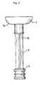
- this syringe 1 is conventionally equipped with a piston 5 adapted to slide tightly inside the latter, and secured, for its actuation, on one end of a piston rod 6 provided with level of its opposite end, a push button 7 having the shape of a cup, that is to say having a face 7a junction with the piston rod 6, convex shape.
- these two injection devices further comprise a protection device after use of the injection needle 3.
- these two protection devices consist of devices of the same design. of injection devices marketed by the company "SAFETY SYRINGES, Inc.”, and described in particular in the patent applications WO 2006/127484 and WO 2006/050304 , and patents US 6,030,366 and US 6,623,459 , these documents being considered, because of their referencing, as an integral part of this description.
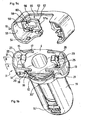
- the protection device of the first injection device shown in FIGS. figures 1b , 3 and 4 comprises a syringe body 8 of the type described in the patent application WO 20061050304 , comprising a longitudinal duct 9 defining a housing for the syringe 1, provided, at one of its ends, with an outer ring 10 for abutment and support of the flange 4 of said syringe.
- This syringe body 8 further comprises a tubular digital grip head 11 formed around the end section of the longitudinal duct 9 on which the crown 10 is formed.
- This tubular head 11 is formed of two half-shells 12, 13 extending symmetrically on either side of the ring and each connected to the latter by two parallel arms extended, each, with a trigger 16, 17 elastically deformable, and adapted so that the tumblers 16, 17 of two coplanar arms define, with the face opposite the 10, a housing 18 and locking the outer flange 4 of the syringe 1.
- the protection device of the first injection device according to the invention also comprises a protective case 19 adapted to slide externally along the tubular conduit 9 of the syringe body 8.
- This protective case 19 comprises, firstly, two digital gripping fins 21, 22 arranged and shaped to close substantially the open face facing the tubular head 11.
- this protective case 19 comprises two locking fingers 22, 23 arranged to extend symmetrically on either side of the tubular duct 9, each from one of the digital gripping fins 20, 21, and adapted to lock in translation the protective case 19 relative to the syringe body 8, in a retracted relative position of said protective case where the injection needle 3 protrudes from the latter.
- Each of these locking fingers 22, 23 consists of an elastically deformable blade extending beyond the flange 4 of the syringe 1 locked in the lumens 18, and extending, in particular, for this purpose within a notch 24, shown in FIG. figure 9 , formed on the periphery of the ring 10 of the syringe body 8.
- Each blade 22, 23 further comprises an intermediate locking member adapted to rest and lock on the ring 10 on either side of the notch 24 formed in the latter, the said locking member consisting of a cross defining two locking studs 25, 26 extending on either side of said blade.
- Each blade 22, 23 comprises, finally, a bead 27 formed at its free end and adapted to form a bearing surface complementary to the convex face of the push button 7 of the piston rod 6, able to trigger an unlocking of the locking studs 25, 26 by deformation of each blade 22, 23 at the end of stroke of said piston rod 6.
- the protective case also comprises four locking fingers such as 28, 29 distributed around the tubular duct 9, each arranged to extend from one of the digital intake fins 20, 21, and adapted to lock in translation the protective case 19 relative to the syringe body 8, in a deployed relative position of said protective case where the injection needle 3 is entirely housed in the latter.
- Each of these locking fingers 28. 29 consists of an elastically deformable blade provided, at its free end, with a locking pin 30 adapted to be housed in a notch 31 formed along the longitudinal duct 9 , and represented at figure 10 .
- the protective device also comprises a spring (not shown) disposed between the syringe body 8 and the protective case 19 and adapted to cause relative sliding of the latter at the end of injection.
- the piston rod 6 comprises a flange 32 formed in the intermediate position of the length of said piston rod.
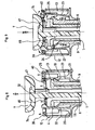
- this locking element 33 is adapted to fit inside the digital capture head 11.
- a locking plate 34 adapted to extend substantially in the plane of the face of the digital gripping head opposite to the digital gripping wings 20, 21, with respect to which four feet such as 35, 36 adapted to extend inside the digital pick-up head 11, and ending with a hook 37 delimiting a longitudinal groove 38 adapted to house, with a clearance clearance, the rim of the crown 10.
- the locking plate 34 further comprises, facing each locking pin 22, 23, a U-shaped cutout 39 defining two parallel branches 40, 41 adapted to be positioned in abutment each against a locking pin 25, 26 .
- each leg 40, 41 has, in addition, the shape of a pin 42 adapted to be housed in a notch 43 of complementary shape formed in the opposite face of each locking pin 25,26.
- the locking element 33 is positioned so that the lugs 42 of the branches 40, 41 are housed in the notches 43 of the locking studs 25, 26.
- This locking element 33 is thus in a so-called deactivation position in which it prevents any relative spacing of the locking fingers 22, 23, and therefore any unlocking of said locking fingers.
- the first actuation of the piston 5 to empty the syringe for the purpose of mixing the solvent and the freeze-dried product does not generate no change in the position of the locking element 33: the passage through the intermediate flange 32 of the piston rod 6 of the obstacle constituted by the abutment piece 46 does not cause, in effect, a tilting without consequence lever 44.
- the intermediate flange 32 abuts against the abutment piece 46 and causes a tilting of the lever 44 which causes a bracing of the branches 47, 48 on the pads 25, 26: the locking element 33 undergoes an axial displacement and is positioned in a so-called activation state in which the branches 40, 41 are disposed beyond the locking studs 25, 26 and therefore more opposed to the relative spacing of the locking fingers 22, 23.
- the protection device of the second embodiment of the injection device according to the invention shown in FIGS. figures 5b , 6 and 7 comprises a syringe body 8 and a protective case similar to those described above.
- piston rod 6 is similar to that described above and shown in FIG. figure 2 .
- the locking element 51 is adapted to cap the digital capture head 11.
- a locking plate 52 adapted to extend substantially in the plane of the face of the digital pick-up head 11 opposite to the digital gripping wings 20, 21, with respect to which extends a skirt 53 adapted to cap the pins.
- this locking element 51 has lugs 54 arranged protruding from the inner face of the skirt 53 and adapted to snap without play under the arms 14, 15 of the tubular head 11.
- This locking element 51 further comprises associated with each locking pin 22, 23, a locking piece 55 disposed inside the skirt 53, said locking piece having a clean elasticity and being connected to the skirt 53 by a connection such that it has a faculty of elastic deformation.
- the locking element 51 is fixed without play on the digital pick-up head 11, and is initially positioned, as shown in FIGS. Figures 6 and 7 , so that the lugs 60 of the branches 58, 59 are housed in the notches 43 of the locking studs 25, 26.
- This locking element 51 is thus in a deactivation position in which it prohibits any relative spacing of the locking fingers 22, 23, and therefore any unlocking of said locking fingers.
- the intermediate flange 32 abuts against the crossmember 57 and causes a deformation of the locking piece 55 and in particular the branches 58, 59 which cause a positioning of the lugs 60 beyond the locking studs 25, 26, for which said branches are no longer opposed to a relative spacing of the locking fingers 22, 23.
- the invention thus leads to converting a disposable secure injection device into a secure injection device which, without requiring any specific action by the user, first actuation of the piston, then the actual injection accompanied by securing.
Landscapes
- Health & Medical Sciences (AREA)
- Engineering & Computer Science (AREA)
- Heart & Thoracic Surgery (AREA)
- Vascular Medicine (AREA)
- Anesthesiology (AREA)
- Biomedical Technology (AREA)
- Environmental & Geological Engineering (AREA)
- Hematology (AREA)
- Life Sciences & Earth Sciences (AREA)
- Animal Behavior & Ethology (AREA)
- General Health & Medical Sciences (AREA)
- Public Health (AREA)
- Veterinary Medicine (AREA)
- Infusion, Injection, And Reservoir Apparatuses (AREA)
Claims (6)
- Geschützte Vorrichtung zur Injektion eines medikamentösen Produktes, wie ein lyophilisiertes Produkt, mit einem Spritzenkörper (8) mit einem Behälter (1), der eine Injektionsnadel (3) trägt und mit einem Kolben (5) versehen ist, der durch einen Kolbenstift (6) betätigt wird, der mit einem Druckknopf (7) versehen ist, und eine Schutzvorrichtung mit:• einer Schutzhülle (19), die angepasst ist, damit die Schutzhülle und der Spritzenkörper (8) geeignet sind, relativ in Bezug zueinander zwischen eine Injektionsposition zu gleiten, in welcher sich die Injektionsnadel (3) zumindest teilweise in die Verlängerung der Schutzhülle (19) erstreckt, und einer Schutzposition nach Verwendung in welcher die Injektionsnadel (3) vollständig in der Schutzhülle (19) untergebracht ist,• zumindest einem Verriegelungsorgan (22, 23), das geeignet ist, einen Verriegelungszustand zum Halten des Spritzenkörpers (8) und der Schutzhülle (19) in ihrer Injektionsposition bereitzustellen, und zum Schalten in einen entriegelten Zustand, der geeignet ist am Ende des Hubes des Kolbens (5) an der Innenseite des Behälters (1) das relative Gleiten des Spritzenkörpers (8) und der Schutzhülle (19) in ihre Schutzposition nach Verwendung zuzulassen,• einem Anschlag (32), der in mittlerer Position der Länge des Kolbenstiftes (6) vorgesehen ist,• und einem Verriegelungselement (33; 51), das auf einem der Elemente, Spritzenkörper (8) oder Schutzhülle (19), verbunden ist,
wobei die Injektionsvorrichtung dadurch gekennzeichnet ist, dass das Verriegelungselement aufweist:• Blockierorgane (40; 41; 58; 59), Verriegelungsorgane (22, 23), die geeignet sind zwischen eine native Anfangsposition versetzt zu werden, sozusagen zur Deaktivierung, zur Blockade von jedem Verriegelungsorgan (22, 23) in dessen Verriegelungszustand und einer Position, sozusagen zur Aktivierung, zum Zulassen einer Schaltung von jedem Verriegelungsorgan (22, 23) in dessen entriegeltem Zustand,• und Betätigungsorgane (44; 57), die mit den Blockierorganen (40, 41; 58; 59) verbunden sind, die auf dem Weg des mittleren Anschlags (32) des Kolbenstiftes (6) angeordnet sind und angepasst sind, um eine Zustandsänderung zu erfahren, die eine Versetzung der Blockierorgane von ihrer Deaktivierungsposition in ihre Aktivierungsposition herbeiführt, bei einer ausgeübten Belastung auf die Betätigungsorgane durch den mittleren Anschlag (32) bei einer Versetzung des Kolbenstiftes (6), die durch einen auf dem Druckknopf (7) ausgeübten Zug eingeführt wird. - Injektionsvorrichtung nach Anspruch 1,
dadurch gekennzeichnet, dass• das Verriegelungselement (33) auf einem der Elemente, Spritzenkörper (8) oder Schutzhülle (19), verbunden ist, mit einer Befähigung in eine parallele Richtung der Längsachse der Schutzvorrichtung zwischen zwei Positionen, die die jeweiligen Positionen der Deaktivierung und der Aktivierung der Blockierorgane (40, 41) der Verriegelungsorgane (22, 23) definieren, auszulen-ken,• die Betätigungsorgange zumindest einen Hebel (44) aufweisen, der gelenkig auf dem Verriegelungselement (33) um eine Schwenkachse (45) herum angebunden ist, und der auf beiden Seiten der Schwenkachse erstreckend aufweist:• einen Kontaktbereich (46), der auf dem Weg des mittleren Anschlags (32) des Kolbenstifts (6) angeordnet ist,• und zumindest ein Verklemmungsteil (47, 48), das geeignet ist, eine Auslenkung des Verriegelungselementes (33) zu erzeugen, das eine Versetzung der Blockierorgane (40, 41) von ihrer Deaktivierungsposition in ihre Aktivierungsposition herbeiführt, bei einer Neigung des Hebels (44), die durch die Versetzung des Kolbenstiftes (6) verursacht wird, die durch einen auf dem Druckknopf (7) ausgeübten Zug engeführt wird. - Injektionsvorrichtung nach Anspruch 1,
dadurch gekennzeichnet, dass• das Verriegelungselement (51) in feststehender Position auf einem der Elemente, Spritzenkörper (8) oder Schutzhülle (19), verbunden ist,• die Betätigungsorgane zumindest ein Verriegelungsteil (55) aufweisen, das mit dem Verriegelungselement (51) fest verbunden ist, mit in einem Stück• einem Kontaktbereich (57), der auf dem Weg des mittleren Anschlags (32) des Kolbenstiftes (6) angeordnet ist,• zumindest einem Blockierorgan (58, 59) des Verriegelungsorgans (22, 23),• und einem verformbaren Verbindungsbereich (56) zwischen dem Kontaktbereich (57) und jedem Blockierorgan (58; 59), der geeignet ist sich zu verformen und eine Versetzung von jedem Blockierorgan (58; 59) von dessen Deaktivierungsposition in dessen Aktivierungsposition herbeizuführen bei einer ausgeübten Belastung auf den Kontaktbereich (57) durch den mittleren Anschlag (32) bei einer Versetzung des Kolbenstiftes (6), die durch einen auf dem Druckknopf (7) ausgeübten Zug eingeführt wird. - Injektionsvorrichtung nach einem der vorstehenden Ansprüche,
dadurch gekennzeichnet, dass
das Verriegelungselement (33; 51) auf dem Spritzenkörper (8) verbunden ist. - Injektionsvorrichtung nach einem der vorstehenden Ansprüche,
dadurch gekennzeichnet, dass
die Blockierorgane (40, 41; 58; 59) des Verriegelungselementes (33; 51) und die Verriegelungsorgane (22, 23) zum Halten des Spritzenkörpers (8) und der Schutzhülle (19) in deren Injektionsposition abnehmbare komplementäre Verbindungsorgane (42, 43; 60, 43) von der Art einer Stufe/Zapfen aufweisen. - Injektionsvorrichtung nach einem der vorstehenden Ansprüche,
wovon die Verriegelungsorgane (22, 23) zum Halten des Spritzenkörpers (8) und der Schutzhülle (19) in ihrer Injektionsposition aus flexiblen Klingen bestehen,
dadurch gekennzeichnet, dass
die Blockierorgane (40, 41; 58; 59) der Verriegelungsorgane angepasst sind, um in ihrer Deaktivierungsposition die Verformung durch Biegen dieser letzteren zu unterbinden.
Applications Claiming Priority (2)
| Application Number | Priority Date | Filing Date | Title |
|---|---|---|---|
| US81407106P | 2006-06-16 | 2006-06-16 | |
| PCT/FR2007/000979 WO2007144507A1 (fr) | 2006-06-16 | 2007-06-13 | Dispositif securise d'injection d'un produit medicamenteux tel qu'un produit lyophilise |
Publications (2)
| Publication Number | Publication Date |
|---|---|
| EP2029202A1 EP2029202A1 (de) | 2009-03-04 |
| EP2029202B1 true EP2029202B1 (de) | 2013-12-25 |
Family
ID=38478566
Family Applications (1)
| Application Number | Title | Priority Date | Filing Date |
|---|---|---|---|
| EP07788884.0A Active EP2029202B1 (de) | 2006-06-16 | 2007-06-13 | Sicherheitsvorrichtung zur injektion eines medizinprodukts, z.b. eines lyophiliserten produkts |
Country Status (3)
| Country | Link |
|---|---|
| US (1) | US20090270803A1 (de) |
| EP (1) | EP2029202B1 (de) |
| WO (1) | WO2007144507A1 (de) |
Families Citing this family (10)
| Publication number | Priority date | Publication date | Assignee | Title |
|---|---|---|---|---|
| ES2589322T3 (es) | 2008-02-11 | 2016-11-11 | Safety Syringes, Inc. | Jeringa con protector de seguridad de aguja y clip para evitar la liberación del protector durante un proceso de reconstitución |
| EP2623145A1 (de) * | 2012-02-03 | 2013-08-07 | Q Stat Pty Ltd | Einfahrbare Nadelvorrichtung und -verfahren |
| US9248242B2 (en) * | 2012-04-20 | 2016-02-02 | Safety Syringes, Inc. | Anti-needle stick safety device for injection device |
| EP2752211A1 (de) * | 2013-01-07 | 2014-07-09 | F. Hoffmann-La Roche Ltd. | Sicherheitsvorrichtung für eine Injektionsspritze |
| EP2953669B1 (de) * | 2013-02-06 | 2018-10-24 | Weibel CDS AG | Abgabevorrichtung zur abgabe eines fluids |
| EP2978473A4 (de) * | 2013-03-25 | 2016-12-28 | Timothy John Adam | Automatisch einziehbare spritze |
| FR3038840B1 (fr) * | 2015-07-16 | 2017-07-21 | Nemera La Verpilliere | Dispositif de securite pour une seringue d'injection. |
| US10675416B2 (en) * | 2018-08-17 | 2020-06-09 | David Harold Kovacs | Retractable syringe |
| USD1108627S1 (en) | 2023-10-02 | 2026-01-06 | Regeneron Pharmaceuticals, Inc. | Drug-delivery device |
| USD1109322S1 (en) | 2023-10-02 | 2026-01-13 | Regeneron Pharmaceuticals, Inc. | Drug-delivery device |
Family Cites Families (6)
| Publication number | Priority date | Publication date | Assignee | Title |
|---|---|---|---|---|
| ES2082052T3 (es) * | 1990-07-19 | 1996-03-16 | Nardino Righi | Jeringuilla de seguridad, de un solo uso. |
| IT1253104B (it) * | 1991-07-02 | 1995-07-10 | Paolo Romagnoli | Siringa monouso |
| AUPR373001A0 (en) * | 2001-03-14 | 2001-04-12 | Glenord Pty Ltd | Improved non-reusable syringe |
| FR2835753B1 (fr) * | 2002-02-11 | 2004-10-29 | Plastef Investissements | Dispositif de support de securite pour une seringue et ensemble d'un tel dispositif et d'une seringue |
| FR2861310B1 (fr) * | 2003-10-22 | 2006-09-22 | Plastef Investissements | Dispositif de seringue d'injection securise |
| FR2876035B1 (fr) * | 2003-11-14 | 2007-03-30 | Plastic Omnium Cie | Ensemble de securite destine a equiper une seringue et ensemble de seringue |
-
2007
- 2007-06-13 US US12/304,705 patent/US20090270803A1/en not_active Abandoned
- 2007-06-13 WO PCT/FR2007/000979 patent/WO2007144507A1/fr not_active Ceased
- 2007-06-13 EP EP07788884.0A patent/EP2029202B1/de active Active
Also Published As
| Publication number | Publication date |
|---|---|
| US20090270803A1 (en) | 2009-10-29 |
| WO2007144507A1 (fr) | 2007-12-21 |
| EP2029202A1 (de) | 2009-03-04 |
Similar Documents
| Publication | Publication Date | Title |
|---|---|---|
| EP2029202A1 (de) | Sicherheitsvorrichtung zur injektion eines medizinprodukts, z.b. eines lyophiliserten produkts | |
| EP1185323B1 (de) | Einweginjektionsvorrichtung | |
| EP1218047B1 (de) | Injektionsvorrichtung für einmalverwendung | |
| EP1436026B1 (de) | Sicherheitsvorrichtung für eine spritze | |
| EP1148904B9 (de) | Sicherheitsanordnung für spritze vorgefüllt mit flüssigem arzneimittel | |
| EP1053037B1 (de) | Vorrichtung zur automatischen injektion einer dosis eines medikamentenprodukts | |
| EP1530979B1 (de) | Sicherheitseinrichtung für eine Spritzvorrichtung | |
| EP0519922B1 (de) | Spritze mit sich automatisch zurückziehender nadel | |
| EP1235603B1 (de) | Sicherheitsvorrichtung für eine spritze | |
| EP1330279B1 (de) | Injektionsspritze mit einem verschiebbaren nadelschutz | |
| WO1989000432A2 (fr) | Seringue de haute securite non reutilisable | |
| EP1224001B1 (de) | Hypodermatische wegwerfspritze mit arretierbarer schutzhülse | |
| EP3659652A1 (de) | Vorrichtung zum entfernen von einer nadelschutzkappe | |
| EP1372772B1 (de) | Sicherheitsspritze | |
| FR2622804A1 (fr) | Seringue non reutilisable | |
| WO2010012876A2 (fr) | Dispositif sécurisé d'injection à usage unique | |
| WO2012110715A1 (fr) | Dispositif sécurisé d'injection à usage unique | |
| FR3038840A1 (fr) | Dispositif de securite pour une seringue d'injection. | |
| EP1368081B1 (de) | Spritze | |
| FR2720001A1 (fr) | Seringue d'injection à usage médical. |
Legal Events
| Date | Code | Title | Description |
|---|---|---|---|
| PUAI | Public reference made under article 153(3) epc to a published international application that has entered the european phase |
Free format text: ORIGINAL CODE: 0009012 |
|
| 17P | Request for examination filed |
Effective date: 20081231 |
|
| AK | Designated contracting states |
Kind code of ref document: A1 Designated state(s): AT BE BG CH CY CZ DE DK EE ES FI FR GB GR HU IE IS IT LI LT LU LV MC MT NL PL PT RO SE SI SK TR |
|
| AX | Request for extension of the european patent |
Extension state: AL BA HR MK RS |
|
| 111L | Licence recorded |
Free format text: 0101 PLASTEF INVESTISSEMENTS Effective date: 20100310 |
|
| 17Q | First examination report despatched |
Effective date: 20110629 |
|
| DAX | Request for extension of the european patent (deleted) | ||
| GRAP | Despatch of communication of intention to grant a patent |
Free format text: ORIGINAL CODE: EPIDOSNIGR1 |
|
| INTG | Intention to grant announced |
Effective date: 20130709 |
|
| GRAS | Grant fee paid |
Free format text: ORIGINAL CODE: EPIDOSNIGR3 |
|
| GRAA | (expected) grant |
Free format text: ORIGINAL CODE: 0009210 |
|
| 111L | Licence recorded |
Designated state(s): AT BE BG CH CY CZ DE DK EE ES FI FR GB GR HU IE IS IT LT LU LV MC MT NL PL PT RO SE SI SK TR Free format text: EXCLUSIVE LICENSE Name of requester: PLASTEF INVESTISSEMENTS, FR Effective date: 20100310 |
|
| AK | Designated contracting states |
Kind code of ref document: B1 Designated state(s): AT BE BG CH CY CZ DE DK EE ES FI FR GB GR HU IE IS IT LI LT LU LV MC MT NL PL PT RO SE SI SK TR |
|
| REG | Reference to a national code |
Ref country code: GB Ref legal event code: FG4D Free format text: NOT ENGLISH |
|
| REG | Reference to a national code |
Ref country code: CH Ref legal event code: EP Ref country code: CH Ref legal event code: PK Free format text: COMPLEMENT D'ENREGISTREMENT DE LICENCE: LICENCE EXCLUSIVE |
|
| REG | Reference to a national code |
Ref country code: AT Ref legal event code: REF Ref document number: 646229 Country of ref document: AT Kind code of ref document: T Effective date: 20140115 |
|
| REG | Reference to a national code |
Ref country code: IE Ref legal event code: FG4D Free format text: LANGUAGE OF EP DOCUMENT: FRENCH |
|
| REG | Reference to a national code |
Ref country code: DE Ref legal event code: R096 Ref document number: 602007034467 Country of ref document: DE Effective date: 20140220 |
|
| PG25 | Lapsed in a contracting state [announced via postgrant information from national office to epo] |
Ref country code: SE Free format text: LAPSE BECAUSE OF FAILURE TO SUBMIT A TRANSLATION OF THE DESCRIPTION OR TO PAY THE FEE WITHIN THE PRESCRIBED TIME-LIMIT Effective date: 20131225 Ref country code: LT Free format text: LAPSE BECAUSE OF FAILURE TO SUBMIT A TRANSLATION OF THE DESCRIPTION OR TO PAY THE FEE WITHIN THE PRESCRIBED TIME-LIMIT Effective date: 20131225 Ref country code: FI Free format text: LAPSE BECAUSE OF FAILURE TO SUBMIT A TRANSLATION OF THE DESCRIPTION OR TO PAY THE FEE WITHIN THE PRESCRIBED TIME-LIMIT Effective date: 20131225 |
|
| REG | Reference to a national code |
Ref country code: NL Ref legal event code: VDEP Effective date: 20131225 |
|
| REG | Reference to a national code |
Ref country code: AT Ref legal event code: MK05 Ref document number: 646229 Country of ref document: AT Kind code of ref document: T Effective date: 20131225 |
|
| REG | Reference to a national code |
Ref country code: LT Ref legal event code: MG4D |
|
| PG25 | Lapsed in a contracting state [announced via postgrant information from national office to epo] |
Ref country code: LV Free format text: LAPSE BECAUSE OF FAILURE TO SUBMIT A TRANSLATION OF THE DESCRIPTION OR TO PAY THE FEE WITHIN THE PRESCRIBED TIME-LIMIT Effective date: 20131225 |
|
| PG25 | Lapsed in a contracting state [announced via postgrant information from national office to epo] |
Ref country code: EE Free format text: LAPSE BECAUSE OF FAILURE TO SUBMIT A TRANSLATION OF THE DESCRIPTION OR TO PAY THE FEE WITHIN THE PRESCRIBED TIME-LIMIT Effective date: 20131225 Ref country code: IS Free format text: LAPSE BECAUSE OF FAILURE TO SUBMIT A TRANSLATION OF THE DESCRIPTION OR TO PAY THE FEE WITHIN THE PRESCRIBED TIME-LIMIT Effective date: 20140425 |
|
| PG25 | Lapsed in a contracting state [announced via postgrant information from national office to epo] |
Ref country code: CY Free format text: LAPSE BECAUSE OF FAILURE TO SUBMIT A TRANSLATION OF THE DESCRIPTION OR TO PAY THE FEE WITHIN THE PRESCRIBED TIME-LIMIT Effective date: 20131225 Ref country code: SK Free format text: LAPSE BECAUSE OF FAILURE TO SUBMIT A TRANSLATION OF THE DESCRIPTION OR TO PAY THE FEE WITHIN THE PRESCRIBED TIME-LIMIT Effective date: 20131225 Ref country code: RO Free format text: LAPSE BECAUSE OF FAILURE TO SUBMIT A TRANSLATION OF THE DESCRIPTION OR TO PAY THE FEE WITHIN THE PRESCRIBED TIME-LIMIT Effective date: 20131225 Ref country code: ES Free format text: LAPSE BECAUSE OF FAILURE TO SUBMIT A TRANSLATION OF THE DESCRIPTION OR TO PAY THE FEE WITHIN THE PRESCRIBED TIME-LIMIT Effective date: 20131225 Ref country code: PL Free format text: LAPSE BECAUSE OF FAILURE TO SUBMIT A TRANSLATION OF THE DESCRIPTION OR TO PAY THE FEE WITHIN THE PRESCRIBED TIME-LIMIT Effective date: 20131225 Ref country code: CZ Free format text: LAPSE BECAUSE OF FAILURE TO SUBMIT A TRANSLATION OF THE DESCRIPTION OR TO PAY THE FEE WITHIN THE PRESCRIBED TIME-LIMIT Effective date: 20131225 Ref country code: AT Free format text: LAPSE BECAUSE OF FAILURE TO SUBMIT A TRANSLATION OF THE DESCRIPTION OR TO PAY THE FEE WITHIN THE PRESCRIBED TIME-LIMIT Effective date: 20131225 Ref country code: PT Free format text: LAPSE BECAUSE OF FAILURE TO SUBMIT A TRANSLATION OF THE DESCRIPTION OR TO PAY THE FEE WITHIN THE PRESCRIBED TIME-LIMIT Effective date: 20140428 Ref country code: NL Free format text: LAPSE BECAUSE OF FAILURE TO SUBMIT A TRANSLATION OF THE DESCRIPTION OR TO PAY THE FEE WITHIN THE PRESCRIBED TIME-LIMIT Effective date: 20131225 |
|
| REG | Reference to a national code |
Ref country code: DE Ref legal event code: R097 Ref document number: 602007034467 Country of ref document: DE |
|
| PG25 | Lapsed in a contracting state [announced via postgrant information from national office to epo] |
Ref country code: DK Free format text: LAPSE BECAUSE OF FAILURE TO SUBMIT A TRANSLATION OF THE DESCRIPTION OR TO PAY THE FEE WITHIN THE PRESCRIBED TIME-LIMIT Effective date: 20131225 |
|
| PLBE | No opposition filed within time limit |
Free format text: ORIGINAL CODE: 0009261 |
|
| STAA | Information on the status of an ep patent application or granted ep patent |
Free format text: STATUS: NO OPPOSITION FILED WITHIN TIME LIMIT |
|
| 26N | No opposition filed |
Effective date: 20140926 |
|
| REG | Reference to a national code |
Ref country code: DE Ref legal event code: R097 Ref document number: 602007034467 Country of ref document: DE Effective date: 20140926 |
|
| PG25 | Lapsed in a contracting state [announced via postgrant information from national office to epo] |
Ref country code: LU Free format text: LAPSE BECAUSE OF FAILURE TO SUBMIT A TRANSLATION OF THE DESCRIPTION OR TO PAY THE FEE WITHIN THE PRESCRIBED TIME-LIMIT Effective date: 20140613 Ref country code: MC Free format text: LAPSE BECAUSE OF FAILURE TO SUBMIT A TRANSLATION OF THE DESCRIPTION OR TO PAY THE FEE WITHIN THE PRESCRIBED TIME-LIMIT Effective date: 20131225 |
|
| REG | Reference to a national code |
Ref country code: CH Ref legal event code: PL |
|
| GBPC | Gb: european patent ceased through non-payment of renewal fee |
Effective date: 20140613 |
|
| REG | Reference to a national code |
Ref country code: IE Ref legal event code: MM4A |
|
| PG25 | Lapsed in a contracting state [announced via postgrant information from national office to epo] |
Ref country code: IE Free format text: LAPSE BECAUSE OF NON-PAYMENT OF DUE FEES Effective date: 20140613 Ref country code: CH Free format text: LAPSE BECAUSE OF NON-PAYMENT OF DUE FEES Effective date: 20140630 Ref country code: LI Free format text: LAPSE BECAUSE OF NON-PAYMENT OF DUE FEES Effective date: 20140630 |
|
| PG25 | Lapsed in a contracting state [announced via postgrant information from national office to epo] |
Ref country code: SI Free format text: LAPSE BECAUSE OF FAILURE TO SUBMIT A TRANSLATION OF THE DESCRIPTION OR TO PAY THE FEE WITHIN THE PRESCRIBED TIME-LIMIT Effective date: 20131225 Ref country code: GB Free format text: LAPSE BECAUSE OF NON-PAYMENT OF DUE FEES Effective date: 20140613 |
|
| PG25 | Lapsed in a contracting state [announced via postgrant information from national office to epo] |
Ref country code: MT Free format text: LAPSE BECAUSE OF FAILURE TO SUBMIT A TRANSLATION OF THE DESCRIPTION OR TO PAY THE FEE WITHIN THE PRESCRIBED TIME-LIMIT Effective date: 20131225 |
|
| REG | Reference to a national code |
Ref country code: FR Ref legal event code: PLFP Year of fee payment: 10 |
|
| PG25 | Lapsed in a contracting state [announced via postgrant information from national office to epo] |
Ref country code: BG Free format text: LAPSE BECAUSE OF FAILURE TO SUBMIT A TRANSLATION OF THE DESCRIPTION OR TO PAY THE FEE WITHIN THE PRESCRIBED TIME-LIMIT Effective date: 20131225 |
|
| PG25 | Lapsed in a contracting state [announced via postgrant information from national office to epo] |
Ref country code: GR Free format text: LAPSE BECAUSE OF FAILURE TO SUBMIT A TRANSLATION OF THE DESCRIPTION OR TO PAY THE FEE WITHIN THE PRESCRIBED TIME-LIMIT Effective date: 20140326 Ref country code: IT Free format text: LAPSE BECAUSE OF FAILURE TO SUBMIT A TRANSLATION OF THE DESCRIPTION OR TO PAY THE FEE WITHIN THE PRESCRIBED TIME-LIMIT Effective date: 20131225 |
|
| PG25 | Lapsed in a contracting state [announced via postgrant information from national office to epo] |
Ref country code: BE Free format text: LAPSE BECAUSE OF FAILURE TO SUBMIT A TRANSLATION OF THE DESCRIPTION OR TO PAY THE FEE WITHIN THE PRESCRIBED TIME-LIMIT Effective date: 20140630 Ref country code: HU Free format text: LAPSE BECAUSE OF FAILURE TO SUBMIT A TRANSLATION OF THE DESCRIPTION OR TO PAY THE FEE WITHIN THE PRESCRIBED TIME-LIMIT; INVALID AB INITIO Effective date: 20070613 Ref country code: TR Free format text: LAPSE BECAUSE OF FAILURE TO SUBMIT A TRANSLATION OF THE DESCRIPTION OR TO PAY THE FEE WITHIN THE PRESCRIBED TIME-LIMIT Effective date: 20131225 |
|
| REG | Reference to a national code |
Ref country code: FR Ref legal event code: PLFP Year of fee payment: 11 |
|
| REG | Reference to a national code |
Ref country code: FR Ref legal event code: PLFP Year of fee payment: 12 |
|
| REG | Reference to a national code |
Ref country code: DE Ref legal event code: R082 Ref document number: 602007034467 Country of ref document: DE Representative=s name: WUNDERLICH & HEIM PATENTANWAELTE PARTNERSCHAFT, DE |
|
| PGFP | Annual fee paid to national office [announced via postgrant information from national office to epo] |
Ref country code: DE Payment date: 20250627 Year of fee payment: 19 |
|
| PGFP | Annual fee paid to national office [announced via postgrant information from national office to epo] |
Ref country code: FR Payment date: 20250625 Year of fee payment: 19 |