EP2029290B1 - Surfaces ultrahydrophobes et procédés de fabrication associés - Google Patents
Surfaces ultrahydrophobes et procédés de fabrication associés Download PDFInfo
- Publication number
- EP2029290B1 EP2029290B1 EP07732977A EP07732977A EP2029290B1 EP 2029290 B1 EP2029290 B1 EP 2029290B1 EP 07732977 A EP07732977 A EP 07732977A EP 07732977 A EP07732977 A EP 07732977A EP 2029290 B1 EP2029290 B1 EP 2029290B1
- Authority
- EP
- European Patent Office
- Prior art keywords
- surface energy
- particles
- low surface
- layer
- mixture
- Prior art date
- Legal status (The legal status is an assumption and is not a legal conclusion. Google has not performed a legal analysis and makes no representation as to the accuracy of the status listed.)
- Not-in-force
Links
- 238000000034 method Methods 0.000 title claims abstract description 55
- 238000004519 manufacturing process Methods 0.000 title description 6
- 239000000463 material Substances 0.000 claims abstract description 131
- 239000002245 particle Substances 0.000 claims abstract description 56
- 239000000203 mixture Substances 0.000 claims abstract description 51
- 239000007787 solid Substances 0.000 claims abstract description 14
- 239000011159 matrix material Substances 0.000 claims abstract description 13
- XLYOFNOQVPJJNP-UHFFFAOYSA-N water Substances O XLYOFNOQVPJJNP-UHFFFAOYSA-N 0.000 claims description 24
- 238000010438 heat treatment Methods 0.000 claims description 11
- 239000000758 substrate Substances 0.000 claims description 5
- 239000010410 layer Substances 0.000 description 44
- 238000000576 coating method Methods 0.000 description 38
- 239000011248 coating agent Substances 0.000 description 31
- 238000005507 spraying Methods 0.000 description 23
- 238000004140 cleaning Methods 0.000 description 21
- 239000007788 liquid Substances 0.000 description 14
- 229920001343 polytetrafluoroethylene Polymers 0.000 description 12
- 239000004810 polytetrafluoroethylene Substances 0.000 description 12
- 239000000725 suspension Substances 0.000 description 10
- 238000011282 treatment Methods 0.000 description 10
- VYPSYNLAJGMNEJ-UHFFFAOYSA-N Silicium dioxide Chemical compound O=[Si]=O VYPSYNLAJGMNEJ-UHFFFAOYSA-N 0.000 description 7
- 238000004528 spin coating Methods 0.000 description 7
- 229920006362 Teflon® Polymers 0.000 description 6
- 239000011521 glass Substances 0.000 description 6
- 229920000352 poly(styrene-co-divinylbenzene) Polymers 0.000 description 6
- 230000008569 process Effects 0.000 description 6
- 239000007921 spray Substances 0.000 description 6
- 239000004793 Polystyrene Substances 0.000 description 5
- 239000004809 Teflon Substances 0.000 description 5
- 230000015572 biosynthetic process Effects 0.000 description 5
- 238000003618 dip coating Methods 0.000 description 5
- 230000002209 hydrophobic effect Effects 0.000 description 5
- 229920002223 polystyrene Polymers 0.000 description 5
- 239000000654 additive Substances 0.000 description 4
- 238000009826 distribution Methods 0.000 description 4
- 229920000642 polymer Polymers 0.000 description 4
- 239000002904 solvent Substances 0.000 description 4
- 239000000126 substance Substances 0.000 description 4
- 239000002344 surface layer Substances 0.000 description 4
- 230000008901 benefit Effects 0.000 description 3
- 239000000084 colloidal system Substances 0.000 description 3
- 239000000356 contaminant Substances 0.000 description 3
- 230000000694 effects Effects 0.000 description 3
- 230000009969 flowable effect Effects 0.000 description 3
- 229920002313 fluoropolymer Polymers 0.000 description 3
- 239000007789 gas Substances 0.000 description 3
- 239000000377 silicon dioxide Substances 0.000 description 3
- 238000007711 solidification Methods 0.000 description 3
- 230000008023 solidification Effects 0.000 description 3
- 238000012876 topography Methods 0.000 description 3
- MYRTYDVEIRVNKP-UHFFFAOYSA-N 1,2-Divinylbenzene Chemical compound C=CC1=CC=CC=C1C=C MYRTYDVEIRVNKP-UHFFFAOYSA-N 0.000 description 2
- IJGRMHOSHXDMSA-UHFFFAOYSA-N Atomic nitrogen Chemical compound N#N IJGRMHOSHXDMSA-UHFFFAOYSA-N 0.000 description 2
- 240000002853 Nelumbo nucifera Species 0.000 description 2
- PPBRXRYQALVLMV-UHFFFAOYSA-N Styrene Chemical compound C=CC1=CC=CC=C1 PPBRXRYQALVLMV-UHFFFAOYSA-N 0.000 description 2
- BOTDANWDWHJENH-UHFFFAOYSA-N Tetraethyl orthosilicate Chemical compound CCO[Si](OCC)(OCC)OCC BOTDANWDWHJENH-UHFFFAOYSA-N 0.000 description 2
- 238000005299 abrasion Methods 0.000 description 2
- 238000013459 approach Methods 0.000 description 2
- 239000007900 aqueous suspension Substances 0.000 description 2
- 230000009286 beneficial effect Effects 0.000 description 2
- 238000001354 calcination Methods 0.000 description 2
- 230000015556 catabolic process Effects 0.000 description 2
- 239000003093 cationic surfactant Substances 0.000 description 2
- 230000006378 damage Effects 0.000 description 2
- 238000006731 degradation reaction Methods 0.000 description 2
- 238000000151 deposition Methods 0.000 description 2
- 230000008021 deposition Effects 0.000 description 2
- 239000003599 detergent Substances 0.000 description 2
- 239000006185 dispersion Substances 0.000 description 2
- 238000004090 dissolution Methods 0.000 description 2
- 238000001035 drying Methods 0.000 description 2
- 238000005530 etching Methods 0.000 description 2
- 230000008020 evaporation Effects 0.000 description 2
- 238000001704 evaporation Methods 0.000 description 2
- 230000004927 fusion Effects 0.000 description 2
- 229920001600 hydrophobic polymer Polymers 0.000 description 2
- 150000002500 ions Chemical class 0.000 description 2
- 230000008018 melting Effects 0.000 description 2
- 238000002844 melting Methods 0.000 description 2
- 238000000465 moulding Methods 0.000 description 2
- 239000002105 nanoparticle Substances 0.000 description 2
- -1 polytetrafluoroethylene Polymers 0.000 description 2
- 230000000717 retained effect Effects 0.000 description 2
- 239000013545 self-assembled monolayer Substances 0.000 description 2
- 238000007493 shaping process Methods 0.000 description 2
- 239000000243 solution Substances 0.000 description 2
- 238000003892 spreading Methods 0.000 description 2
- 230000007480 spreading Effects 0.000 description 2
- 239000001993 wax Substances 0.000 description 2
- 241000196324 Embryophyta Species 0.000 description 1
- 241000238631 Hexapoda Species 0.000 description 1
- 240000007472 Leucaena leucocephala Species 0.000 description 1
- 235000010643 Leucaena leucocephala Nutrition 0.000 description 1
- 235000006508 Nelumbo nucifera Nutrition 0.000 description 1
- 235000006510 Nelumbo pentapetala Nutrition 0.000 description 1
- 239000006057 Non-nutritive feed additive Substances 0.000 description 1
- 239000000853 adhesive Substances 0.000 description 1
- 238000004026 adhesive bonding Methods 0.000 description 1
- 230000001070 adhesive effect Effects 0.000 description 1
- 238000007743 anodising Methods 0.000 description 1
- 239000007864 aqueous solution Substances 0.000 description 1
- 239000000969 carrier Substances 0.000 description 1
- 238000005266 casting Methods 0.000 description 1
- 239000000919 ceramic Substances 0.000 description 1
- 229910010293 ceramic material Inorganic materials 0.000 description 1
- 230000008859 change Effects 0.000 description 1
- 238000006243 chemical reaction Methods 0.000 description 1
- 239000011247 coating layer Substances 0.000 description 1
- 239000004035 construction material Substances 0.000 description 1
- 238000010411 cooking Methods 0.000 description 1
- 238000001816 cooling Methods 0.000 description 1
- 230000000593 degrading effect Effects 0.000 description 1
- 239000003814 drug Substances 0.000 description 1
- 239000000428 dust Substances 0.000 description 1
- 238000004070 electrodeposition Methods 0.000 description 1
- 230000005670 electromagnetic radiation Effects 0.000 description 1
- 235000013305 food Nutrition 0.000 description 1
- 238000010348 incorporation Methods 0.000 description 1
- 230000014759 maintenance of location Effects 0.000 description 1
- 239000000693 micelle Substances 0.000 description 1
- 238000002156 mixing Methods 0.000 description 1
- 230000004048 modification Effects 0.000 description 1
- 238000012986 modification Methods 0.000 description 1
- 239000000178 monomer Substances 0.000 description 1
- 230000007935 neutral effect Effects 0.000 description 1
- 229910052757 nitrogen Inorganic materials 0.000 description 1
- 238000000059 patterning Methods 0.000 description 1
- 239000002861 polymer material Substances 0.000 description 1
- 239000011148 porous material Substances 0.000 description 1
- 239000000843 powder Substances 0.000 description 1
- 238000012545 processing Methods 0.000 description 1
- 238000007788 roughening Methods 0.000 description 1
- 239000004576 sand Substances 0.000 description 1
- 238000001878 scanning electron micrograph Methods 0.000 description 1
- 238000004626 scanning electron microscopy Methods 0.000 description 1
- 239000002094 self assembled monolayer Substances 0.000 description 1
- 238000004544 sputter deposition Methods 0.000 description 1
- 238000000859 sublimation Methods 0.000 description 1
- 230000008022 sublimation Effects 0.000 description 1
- 230000003746 surface roughness Effects 0.000 description 1
- 239000004094 surface-active agent Substances 0.000 description 1
- 238000002604 ultrasonography Methods 0.000 description 1
- 238000009736 wetting Methods 0.000 description 1
Images


Classifications
-
- B—PERFORMING OPERATIONS; TRANSPORTING
- B05—SPRAYING OR ATOMISING IN GENERAL; APPLYING FLUENT MATERIALS TO SURFACES, IN GENERAL
- B05D—PROCESSES FOR APPLYING FLUENT MATERIALS TO SURFACES, IN GENERAL
- B05D5/00—Processes for applying liquids or other fluent materials to surfaces to obtain special surface effects, finishes or structures
- B05D5/08—Processes for applying liquids or other fluent materials to surfaces to obtain special surface effects, finishes or structures to obtain an anti-friction or anti-adhesive surface
- B05D5/083—Processes for applying liquids or other fluent materials to surfaces to obtain special surface effects, finishes or structures to obtain an anti-friction or anti-adhesive surface involving the use of fluoropolymers
-
- C—CHEMISTRY; METALLURGY
- C03—GLASS; MINERAL OR SLAG WOOL
- C03C—CHEMICAL COMPOSITION OF GLASSES, GLAZES OR VITREOUS ENAMELS; SURFACE TREATMENT OF GLASS; SURFACE TREATMENT OF FIBRES OR FILAMENTS MADE FROM GLASS, MINERALS OR SLAGS; JOINING GLASS TO GLASS OR OTHER MATERIALS
- C03C17/00—Surface treatment of glass, not in the form of fibres or filaments, by coating
- C03C17/006—Surface treatment of glass, not in the form of fibres or filaments, by coating with materials of composite character
-
- C—CHEMISTRY; METALLURGY
- C03—GLASS; MINERAL OR SLAG WOOL
- C03C—CHEMICAL COMPOSITION OF GLASSES, GLAZES OR VITREOUS ENAMELS; SURFACE TREATMENT OF GLASS; SURFACE TREATMENT OF FIBRES OR FILAMENTS MADE FROM GLASS, MINERALS OR SLAGS; JOINING GLASS TO GLASS OR OTHER MATERIALS
- C03C17/00—Surface treatment of glass, not in the form of fibres or filaments, by coating
- C03C17/34—Surface treatment of glass, not in the form of fibres or filaments, by coating with at least two coatings having different compositions
- C03C17/3405—Surface treatment of glass, not in the form of fibres or filaments, by coating with at least two coatings having different compositions with at least two coatings of organic materials
-
- B—PERFORMING OPERATIONS; TRANSPORTING
- B05—SPRAYING OR ATOMISING IN GENERAL; APPLYING FLUENT MATERIALS TO SURFACES, IN GENERAL
- B05D—PROCESSES FOR APPLYING FLUENT MATERIALS TO SURFACES, IN GENERAL
- B05D3/00—Pretreatment of surfaces to which liquids or other fluent materials are to be applied; After-treatment of applied coatings, e.g. intermediate treating of an applied coating preparatory to subsequent applications of liquids or other fluent materials
- B05D3/02—Pretreatment of surfaces to which liquids or other fluent materials are to be applied; After-treatment of applied coatings, e.g. intermediate treating of an applied coating preparatory to subsequent applications of liquids or other fluent materials by baking
- B05D3/0254—After-treatment
-
- C—CHEMISTRY; METALLURGY
- C03—GLASS; MINERAL OR SLAG WOOL
- C03C—CHEMICAL COMPOSITION OF GLASSES, GLAZES OR VITREOUS ENAMELS; SURFACE TREATMENT OF GLASS; SURFACE TREATMENT OF FIBRES OR FILAMENTS MADE FROM GLASS, MINERALS OR SLAGS; JOINING GLASS TO GLASS OR OTHER MATERIALS
- C03C2217/00—Coatings on glass
- C03C2217/40—Coatings comprising at least one inhomogeneous layer
-
- C—CHEMISTRY; METALLURGY
- C03—GLASS; MINERAL OR SLAG WOOL
- C03C—CHEMICAL COMPOSITION OF GLASSES, GLAZES OR VITREOUS ENAMELS; SURFACE TREATMENT OF GLASS; SURFACE TREATMENT OF FIBRES OR FILAMENTS MADE FROM GLASS, MINERALS OR SLAGS; JOINING GLASS TO GLASS OR OTHER MATERIALS
- C03C2217/00—Coatings on glass
- C03C2217/70—Properties of coatings
- C03C2217/76—Hydrophobic and oleophobic coatings
-
- C—CHEMISTRY; METALLURGY
- C03—GLASS; MINERAL OR SLAG WOOL
- C03C—CHEMICAL COMPOSITION OF GLASSES, GLAZES OR VITREOUS ENAMELS; SURFACE TREATMENT OF GLASS; SURFACE TREATMENT OF FIBRES OR FILAMENTS MADE FROM GLASS, MINERALS OR SLAGS; JOINING GLASS TO GLASS OR OTHER MATERIALS
- C03C2217/00—Coatings on glass
- C03C2217/70—Properties of coatings
- C03C2217/77—Coatings having a rough surface
-
- C—CHEMISTRY; METALLURGY
- C03—GLASS; MINERAL OR SLAG WOOL
- C03C—CHEMICAL COMPOSITION OF GLASSES, GLAZES OR VITREOUS ENAMELS; SURFACE TREATMENT OF GLASS; SURFACE TREATMENT OF FIBRES OR FILAMENTS MADE FROM GLASS, MINERALS OR SLAGS; JOINING GLASS TO GLASS OR OTHER MATERIALS
- C03C2218/00—Methods for coating glass
- C03C2218/10—Deposition methods
- C03C2218/11—Deposition methods from solutions or suspensions
- C03C2218/112—Deposition methods from solutions or suspensions by spraying
-
- Y—GENERAL TAGGING OF NEW TECHNOLOGICAL DEVELOPMENTS; GENERAL TAGGING OF CROSS-SECTIONAL TECHNOLOGIES SPANNING OVER SEVERAL SECTIONS OF THE IPC; TECHNICAL SUBJECTS COVERED BY FORMER USPC CROSS-REFERENCE ART COLLECTIONS [XRACs] AND DIGESTS
- Y10—TECHNICAL SUBJECTS COVERED BY FORMER USPC
- Y10T—TECHNICAL SUBJECTS COVERED BY FORMER US CLASSIFICATION
- Y10T428/00—Stock material or miscellaneous articles
- Y10T428/24—Structurally defined web or sheet [e.g., overall dimension, etc.]
- Y10T428/24355—Continuous and nonuniform or irregular surface on layer or component [e.g., roofing, etc.]
Definitions
- the invention relates to provision of ultrahydrophobic surfaces.
- the invention provides novel methods for the production of ultrahydrophobic surfaces, and novel products of such methods.
- the general requirements for obtaining ultrahydrophobic surfaces having these properties have been known for many years, since the publications of Wenzel (Ind. Eng. Chem., 1936, 28, 988 ) and Cassie and Baxter (Trans. Faraday Soc. 1944, 40, 546 ).
- the surface must be formed from a material which is apolar/hydrophobic and has water contact angle above 90°.
- the surface must also be provided with some degree of surface roughness or patterning.
- Surfaces of this type exhibit the three characteristic features of self-cleaning surfaces, namely: (1) they exhibit weak adhesion of nearly every type of surface contaminant, (2) the tilt angle required to cause water to run off is very low, and (3) surface contaminants are removed by water run-off in the absence of additives such as detergents.
- US 3904795 describes applying a coating of an aqueous dispersion of particles of a fusible water-insoluble addition polymer, drying the coating such that the water evaporates completely and heating the coating so that the particles fuse to a continuous uncracked film.
- This method provides a surface which has some self-cleaning properties but they are insufficient.
- CA 2260470 describes a structure having projections of height 50 nm to 10 microns and spacing 50 nm to 10 microns, and aspect ratio 0.5 to 20. It is suggested that the structured surface can be provided by various methods including mechanical impression, lithographic etching, or shaping.
- US 6660363 similarly describes a surface which is provided with a layer of adhesive and then particles of low surface energy material such as PTFE or other hydrophobic polymer are adhered to the surface. This results in elevations 5 to 200 microns apart and 5 to 100 microns in height.
- the intention is stated to be providing the particles of hydrophobic polymer close enough together to avoid water contacting the surface between the elevations.
- the polymer powder can be applied for instance by stamping, gluing or chemical or physical etching. Generally the particles are applied as a solution or dispersion and then the coating is dried or cured.
- CA 2356178 teaches that a surface having topography which complies with a particular definition results in improved self-cleaning properties of that surface.
- the definition is said to require raised areas and depressions of 0.1 nm to 1 mm depth or height.
- the topography can be provided by various structures such as conical particles, including those having additional projections, and scratches, including those having non-smooth interior surfaces. Methods for producing the desired topography include moulding and anodising the surface.
- WO 01/19932 is similar in that it describes application to a surface of a coating containing a film former and insoluble particles of size 10 to 50 microns, together with a solvent.
- the coating is applied to the relevant surface in such a way that the particles have a spacing 5 to 100 microns and the solvent is allowed to evaporate, leaving a layer of film former having embedded therein the particles.
- WO 2004/037944 also describes modifying a surface to provide protrusions with the application of particles having size below 300 nm.
- US 2002/034627 addresses the problem of improving durability of a self-cleaning surface. This approaches the problem by providing a mesoporous ceramic film.
- a layer is produced by providing monomer of tetraethoxysilane (TEOS) containing micelles of cationic surfactant. Once the layer has been formed, the cationic surfactant is removed by calcining, leaving (in the Examples) pores of size around 3 nm. The maximum size mentioned generally is 40 nm.
- the film is around 1 micron thick in the Examples and up to 10 microns thick in general.
- the surface produced is formed of a high surface energy material, which therefore must be modified in order to render the surface as a whole self-cleaning.
- a disadvantage of this system is that a surface chemical treatment of this type is easily degraded by UV light or simple abrasion, destroying the self-cleaning effect. This is particularly problematic, given that the mesoporous ceramic material itself is of high surface energy.
- this system involves a surface chemical treatment which is easily degraded, for instance by abrasion, destroying the self-cleaning effect. This then reveals the high surface energy silica material underneath.
- the present invention addresses the problem of providing self-cleaning surfaces which are mechanically robust, and thus industrially useful, and which retain their self-cleaning properties for a significant period of time despite major use.
- the document EP-A2-0 933 388 teaches to produce a coated ultrahydrophobic surface with an array of elevations and depressions by a forming step after or simultaneously with the coating step.
- the invention aims in particular to do this by means of methods which are convenient to operate on an industrial scale and which allow predictability of the final structure.
- the invention provides a method of producing an ultrahydrophobic surface, the method comprising providing a mixture comprising low surface energy material and sacrificial material, forming a layer from the mixture, wherein the layer contains particles of sacrificial material, treating the layer so as to destroy the particles of sacrificial material and to generate a laterally continuous matrix of low surface energy material containing an array of depressions.
- the formed ultrahydrophobic surface comprises a laterally continuous matrix of low surface energy material containing depressions. That means the depressions are surrounded by a continuous network of elevations.
- the projections are surrounded by a continuous, interconnected network of valleys.
- the projections are formed of low surface energy material and in other cases the matrix is also formed of low surface energy material.
- the invention has the advantage that the structure of the surface means that it has greater mechanical robustness than surfaces of the prior art and retains the self-cleaning properties for a longer period than surfaces of the prior art.
- the defined structure has the particular advantage that even with some degree of wear of the low surface energy material the structure of the surface is retained, maintaining the self-cleaning properties.
- the surface of the invention has the advantage over US 2002/034627 and Gu et al discussed above of longer retention of self-cleaning properties.
- a key aspect of the method of the invention is the formation of a layer which comprises particles of sacrificial material distributed throughout a low surface energy material, and then destroying the particles whilst leaving the low surface energy material in solid form.
- depressions or pits
- the particles of sacrificial material can be destroyed by a method which removes the sacrificial material from the surface altogether or by a method which allows incorporation of the sacrificial material into other elements of the surface, for instance by dissolution.
- the surface comprises a laterally continuous matrix of low surface energy material in which the array of depressions is disposed.
- This continuity can arise from solidification of a liquid low surface energy material.
- the low surface energy material may be present in the mixture and in the layer in solid form and can, for instance, be fused so as to provide a continuous matrix. Any fusing may happen sequentially or simultaneously with the step of destruction of the particles of sacrificial material.
- a mixture comprising sacrificial material.
- a single type of sacrificial material may be used, or mixtures of more than one type. Any material may be used which is capable of being treated when in particulate form so that the particles are destroyed and the low surface energy material is retained.
- the sacrificial material can for instance be a polymer, a crystalline or amorphous solid state material or even a liquid. It is necessary that the mixture is generated in such a way that the sacrificial material can be in particulate form in the layer.
- the particles may be in solid or liquid form, preferably solid form.
- the sacrificial material may be such that it is not in the form of particles in the mixture until it is treated in some way to form particles when it is in the layer.
- the mixture also comprises low surface energy material.
- a low surface energy material has a water contact angle greater than 90° when in the form of a plane, unstructured surface. That is, a drop of water placed onto a plane, unstructured surface of the low surface energy material has a contact angle of greater than 90°.
- the low surface energy material can be selected from highly hydrophobic materials such as fluorinated polymers, for example polytetrafluoroethylene (PTFE). Also usable are mixtures of polymers with additives which during processing render the polymer material hydrophobic. These include for example low molecular weight additives, self-assembled monolayers and waxes. What is essential is that there is a laterally continuous matrix of material which has low surface energy.
- highly hydrophobic materials such as fluorinated polymers, for example polytetrafluoroethylene (PTFE).
- PTFE polytetrafluoroethylene
- additives which during processing render the polymer material hydrophobic. These include for example low molecular weight additives, self-assembled monolayers and waxes. What is essential is that there is a laterally continuous matrix of material which has low surface energy.
- a single low surface energy material may be used, or mixtures.
- the mixture may comprise only sacrificial material and low surface energy material or it may comprise other components, such as processing aids or carriers.
- the mixture as a whole may be in liquid or granular (particulate) form. It is generally flowable so that it is possible to form a layer.
- the sacrificial material is in solid particulate form in the mixture.
- the low surface energy material is in solid particulate form in the blend.
- a carrier liquid usually as a suspension, often a colloidal suspension.
- Any compatible carrier liquid can be used, and water is preferred.
- the ratio of the amounts (by weight) of low surface energy material: sacrificial material can be chosen according to the array of depressions it is intended to provide, but generally is in the range 10:1 to 1:10, more preferably 1:6 to 1:2.
- the mixture may be formed as a layer which is a coating on an article which is required to have self-cleaning properties.
- Any appropriate coating technique can be used, such as spin-coating, dip-coating, spreading, spraying, application with a brush or roller.
- the sacrificial material and the low surface energy material are provided as a mixture, usually in a carrier liquid as discussed above, and then this mixture is sprayed on to the surface to be coated.
- the distance between the spray position and the surface to be coated is conventional, as is the duration of spraying which is generally chosen according to the amount of the mixture to be applied.
- the distance between the spray position and the surface to coated is at least 15 cm, preferably at least 20 cm. This results in a more appropriate pattern of application of the mixture to the surface and better ultrahydrophobicity properties.
- Suitable temperatures for the preheated surface are at least 100°C, preferably at least 150°C.
- pretreat the surface of the article before application of the mixture of sacrificial material and low surface energy material to form the layer. For instance, it can be desirable to roughen the surface of the article itself prior to application of any materials to it.
- Suitable primers for low surface energy materials such as PTFE include water based primers of the type supplied by DuPont under the trade name 459-ATX, 459-804, PTFE 852-20x or 852-200.
- any suitable methods can be used, such as spin-coating, dip-coating, spreading, spraying and application with a brush or roller. Spin-coating, dip-coating and spraying are preferred.
- primer After application of primer it is preferred to subject the primer to a heat treatment process for at least five minutes, preferably at least ten minutes, up to 25 or 30 minutes, for instance about 15 minutes.
- the heat treatment temperature is usually at least 200°C, for instance about 250°C.
- this pre-coating is preferably applied by spraying, although spin-coating may also be used.
- the pre-coating of low surface energy material is preferably heat treated after application, for instance for at least five minutes, in particular about ten minutes.
- the treatment temperature is usually at least 300°C, often at least 350°C, for instance about 385°C.
- the application of a pre-coating of low surface energy material in the method of the first aspect of the invention may include any of the preferred features of this further aspect discussed below.
- the layer may be a surface layer of an article which is formed itself from the mixture or which has a surface already formed from the mixture.
- treatment can destroy the particles of sacrificial material in the surface layer of the object, thus providing the article with a structured surface.
- Fabrication of such articles can be by any appropriate method, such as casting, moulding or shaping.
- the layer especially if it is a coating on an article required to have a self-cleaning surface, has thickness similar to the thickness desired for the self-cleaning surface layer itself.
- it can be in the range 100 nm to 100 microns, preferably up to 50 microns, more preferably 100 nm to 25 microns, preferably up to 20 microns.
- Destruction of the particles of sacrificial material can be done, for example, by heating; exposing the layer to a solvent or a gas; irradiation with electromagnetic radiation, electrons, ions or neutral particles; exposure to a plasma; or exposure to ultrasound.
- Other methods can be used provided that the particles of sacrificial material are destroyed, for instance by removal of the sacrificial material altogether by evaporation, sublimation or thermal degradation.
- the particles can be destroyed by dissolution of the sacrificial material into the other materials that are part of the layer or part of the article which is coated.
- the particles of sacrificial material are destroyed by removal of the sacrificial material, often by heating to induce thermal degradation.
- the same heating step can induce melting and fusion of the particles of low surface energy material to provide the laterally continuous matrix. Subsequent cooling then allows solidification.
- the surface may be subjected to a treatment step. This may, for instance, improve appearance or mechanical strength or even improve the self-cleaning properties.
- Such a post-treatment could include: exposure of the article or its surface to elevated temperatures; exposure to solvents or gases; exposure to electromagnetic, ion or other particle irradiation or exposure to a plasma.
- the treatment could include deposition of a further surface layer, deposition of a self-assembled monolayer, wax or any other material or the application by evaporation or sputtering or electro deposition of a further material or modification of the surface by a chemical reaction.
- Such treatments are usually post-treatments effected after the formation of the surface but they may if appropriate also be included in earlier stages of the process.
- the particles of sacrificial material in the layer are often of substantially the same diameter as the depressions in the surface produced, or slightly larger.
- the average (mean) size of the particles of sacrificial material can be from 100 nm to 100 microns, preferably 0.5 to 25 microns, often at least 5 microns. It can be up to 20 or 10 microns.
- the average diameter of the depressions is also preferably in the same ranges.
- the particles of sacrificial material can be aggregates of smaller sub-particles so that the average diameter of the depressions is preferably in the ranges above, but the average diameter of the sub-particles is significantly smaller.
- the average (mean) depth of the depressions is also generally (independently) in the same size ranges as given above for the diameter of the depressions.
- the diameter of a particle is the maximum dimension of the particle.
- the diameter of a depression is the maximum lateral dimension of a depression.
- the particles are often substantially spherical and the depressions are often of substantially circular lateral cross-section.
- the depressions are uniformly distributed across the surface.
- the average (mean) centre-to-centre distance is preferably in the range of 100 nm to 100 microns, more preferably at least 0.5 microns and preferably not more than 10 microns.
- the depressions are preferably in a closely spaced array such that the average diameter of the depressions is greater than the average edge-to-edge distance between them.
- the ratio of the average centre-to-centre distance to the average diameter is less than 2, preferably not more than 1.8, more preferably not more than 1.5.
- the diameter of the depressions, the depth of the depressions and the centre-to-centre spacing of the depressions may vary across the surface. They may have a wide size distribution, in particular, for example, from 4 to 14um.
- the diameter of the depressions, the depth of the depressions and the centre-to-centre spacing of the depressions have, independently, a narrow distribution of sizes.
- at least 50% (by number) of the depressions have the relevant diameter in the range 100 nm to 100 microns (preferably up to 10 microns), more preferably 80% in this range and in particular at least 90% in this range.
- at least 50% have the relevant parameter in the range plus or minus 50% of the average, more preferably plus or minus 30% of the average.
- at least 80%, preferably at least 90% have the relevant dimension within plus or minus 50%, more preferably plus or minus 30%, of the average.
- Each of these size distributions is preferred for each of the three diameters discussed, independently of one another.
- the low surface energy material if present in the mixture in the form of particles, can have any appropriate average diameter, generally not more than 10 microns, preferably not more than 1 micron, often in the range 10 to 900 nm, for instance 100 to 500 nm.
- the thickness of the entire layer is generally in the range 100 nm to 100 microns, preferably 100 nm to 50 microns or 100 nm to 20 microns.
- mixtures which are suitable for use in provision of ultrahydrophobic surfaces.
- Such mixtures are flowable mixtures comprising low surface energy material and particles of sacrificial material.
- the mixture is flowable to facilitate formation of a layer and may be a solid, granular mixture but is preferably a liquid mixture in which particles of sacrificial material are dispersed.
- the low surface energy material is preferably also in particulate form in the mixtures of the fourth aspect of the invention and in this case the particles of sacrificial material and particles of low surface energy material are generally dispersed in a carrier liquid, which can be any convenient inert liquid such as water.
- the sacrificial material is a material which has properties such that the particles formed from it can be destroyed by a treatment to which the low surface energy material is substantially chemically inert. That is, the low surface energy material is generally not chemically affected but may for instance undergo a change of physical state, such as fusion or melting.
- the ratios of sacrificial material to low surface energy material and the size distributions of particles of these are the same as discussed above in connection with other aspects of the invention.
- the sacrificial material and low surface energy material can be of the same types as discussed above in connection with other aspects of the invention.
- a fifth aspect of the invention we provide a method of producing an ultrahydrophobic surface on an article, the method comprising providing an article having a surface and providing a low surface energy material and spraying the low surface energy material onto the surface of the article to form a layer and subjecting the layer to a solidification step.
- the low surface energy material is provided in sprayable form.
- the low surface energy material itself is generally part of a liquid blend comprising low surface energy material and carrier liquid, and this liquid blend is sprayed onto the surface of the article.
- a primer is applied to the surface of the article prior to application of any other layer.
- the primer preferably has the characteristics discussed above in connection with the primer for use in the first aspect of the invention.
- the primer is subjected to a heat treatment after application, also as discussed above.
- the low surface energy material is preferably a highly hydrophobic material such as a fluorinated polymer, for example PTFE.
- the degree of coverage of the surface by the outer layer formed from low surface energy material is important. Preferably it is in the range 15 to 90% (based on the area of the article surface).
- the distance of the spray position from the surface is important and is generally at least 10 cm and preferably at least 15 cm and more preferably at least 20 cm. It is usually not more than 45 cm.
- Spraying time is usually in the range 1 to 30 seconds and a longer spraying time results in greater coverage.
- primer is used it is preferably heat treated, preferably for at least 10 minutes, for instance at about 15 minutes. Heat treatment temperatures can be at least 200°C, for instance about 250°C.
- a pre-coating of low surface energy material is applied then it is preferably heat treated for at least 5 minutes, for instance about 10 minutes.
- Heat treatment temperatures can be at least 300°C, preferably at least 350°C, for instance about 385°C.
- primer and/or pre-coating of low surface energy material are used these can be applied by any appropriate method but spin-coating and spraying are preferred.
- the outer layer comprising low surface energy material is applied by spraying.
- Any suitable spraying apparatus can be used, for instance a spray gun.
- An example is a Sealey airbrush kit.
- the surface onto which the outer layer of low surface energy material is sprayed is heated at the time of spraying.
- it may be at a temperature at least 100°C, for example about 150°C.
- primer is applied to the surface of the article by spin-coating, dip-coating or spraying.
- the layer applied is then heat treated for 10 to 20 minutes at 200 to 300°C.
- a pre-coating of low surface energy material is then applied onto the primer layer by spin-coating or spraying and heat treated for 5 to 15 minutes at 350 to 400°C.
- the outer coating of low surface energy material is then applied by spraying and heat treated for 5 to 10 minutes at 300 to 350°C.
- the ultrahydrophobic surface produced has very low wettability.
- the water contact angle is very high, and wetting of the surface is prevented, causing the formation of drops that make very little contact with the surface.
- These drops roll off even when the inclination of the surface is low, even below 10°. They can pick up and carry off contaminant particles, thereby cleaning the surface.
- the surfaces can be very easily cleaned using water without addition of additives such as detergents.
- the ultrahydrophobic surface has a water contact angle of 140° to 180°, preferably 160 to 180°, measured in a way averaged over the structured surface.
- the ultrahydrophobic surface produced according to the invention can be used as a surface of a wide variety of industrial articles, for numerous uses.
- Examples include coatings for equipment used in the handling of gases, liquids, solid particulates or mixtures, such as in the food, chemicals and pharmaceuticals industries; coatings for glass, such as in windows, laboratory equipment, visors and screens; coatings for cooking utensils; coatings for outdoor surfaces such as buildings, construction materials, information signs; coatings for vehicles, such as body parts and windows for buildings and vehicles such as cars, buses, aeroplanes, trains, etc.; coatings for water-borne machinery such as boats, surf-boards, submarines and oil platforms; coatings for surfaces (eg glass surfaces and mirrors), especially in areas of high humidity such as kitchens and bathrooms.
- coatings for equipment used in the handling of gases, liquids, solid particulates or mixtures such as in the food, chemicals and pharmaceuticals industries
- coatings for glass such as in windows, laboratory equipment, visors and screens
- An aqueous solution was prepared by mixing two colloidal suspensions. These were the Teflon (Trademark) PTFE 30 N aqueous suspension purchased from DuPont, consisting of polytetrafluoroethylene spheres with a diameter of 220 nm in an aqueous suspension, and a suspension of poly(styrene-co-divinylbenzene) spheres with a diameter of 6.4 ⁇ m suspended in water, purchased from Sigma. The ratio of divinylbenzene to styrene was 5 to 95.
- Teflon (Trademark) PTFE 30 N aqueous suspension purchased from DuPont, consisting of polytetrafluoroethylene spheres with a diameter of 220 nm in an aqueous suspension, and a suspension of poly(styrene-co-divinylbenzene) spheres with a diameter of 6.4 ⁇ m suspended in water, purchased from Sigma.
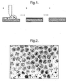
- FIG. 1 shows an image of a surface made from a mixture that contained 26% of Teflon colloids and 74% of poly(styrene-co-divinylbenzene) colloids (by volume).
- the voids on the film stem from the removal of the 6.4 ⁇ m-sized poly(styrene-co-divinylbenzene) spheres.
- a water drop placed on such a surface showed a macroscopic contact angle (i.e it was measured in a way that averaged over the structure on the 1 to 10 ⁇ m scale) of more than 170 degrees.
- Water drops placed on this surface ran off when only slightly perturbed (e.g. by slightly tilting the sample). Dust particles or other dirt that was placed onto the surface was carried off by the water drops that ran off the surface.
- a glass surface was provided. This was sand blasted to result in roughening.
- Primer 459-804 supplied by DuPont was applied using a Sealey airbrush kit model no. AB931 driven by a nitrogen line with a pressure of 3 bar.
- the primer was applied in a thin layer and then heated in a furnace at 250°C for 15 minutes.
- the thin layer was then heated in a furnace at 385°C for 10 minutes until it was set.
- the second, outer coating which forms the ultrahyd rophobic surface was then applied.
- the layer was formed using a blend comprising 1 g of the same PTFE suspension as used to make the pre-coating, 2g water and one 1g polystyrene.
- the pre-coated glass surface was placed on a hot plate and heated to 120°C.
- the second, outer coating was sprayed using the same spray gun as for the primer and pre-coating layers, onto the heated sample.
- FIG. 4 illustrates the process
- Figure 5 illustarates the process and figure 3 is an SEM image of the surface resulting from this process.
Landscapes
- Chemical & Material Sciences (AREA)
- Geochemistry & Mineralogy (AREA)
- Organic Chemistry (AREA)
- Engineering & Computer Science (AREA)
- Chemical Kinetics & Catalysis (AREA)
- General Chemical & Material Sciences (AREA)
- Life Sciences & Earth Sciences (AREA)
- Materials Engineering (AREA)
- Composite Materials (AREA)
- Application Of Or Painting With Fluid Materials (AREA)
- Physical Or Chemical Processes And Apparatus (AREA)
- Immobilizing And Processing Of Enzymes And Microorganisms (AREA)
- Other Surface Treatments For Metallic Materials (AREA)
- Steroid Compounds (AREA)
- Separation Using Semi-Permeable Membranes (AREA)
Claims (15)
- Procédé pour produire une surface ultra hydrophobe, le procédé comprenant les étapes consistant à : fournir un mélange comprenant un matériau à faible énergie de surface et un matériau sacrificiel, former une couche à partir du mélange dans lequel la couche contient des particules du matériau sacrificiel, traiter la couche afin de détruire les particules de matériau sacrificiel et de générer une matrice latéralement continue de matériau solide à faible énergie de surface contenant un réseau de dépressions.
- Procédé selon la revendication 1, comprenant la fourniture d'un substrat et la formation de la couche sur le substrat.
- Procédé selon la revendication 1 ou 2, dans lequel le matériau sacrificiel est sous forme particulaire dans le mélange.
- Procédé selon l'une quelconque des revendications précédentes, dans lequel les particules de matériau sacrificiel sont détruites par chauffage.
- Procédé selon la revendication 4, dans lequel le matériau à faible énergie de surface est sous forme solide particulaire dans le mélange et dans la couche, et le chauffage fusionne les particules pour former une matrice latéralement continue de matériau à faible énergie de surface.
- Procédé selon l'une quelconque des revendications précédentes, dans lequel les dépressions ont un diamètre moyen compris entre 100 nm et 100 microns.
- Procédé selon l'une quelconque des revendications précédentes, dans lequel les dépressions ont un diamètre moyen d'au moins 0,5 microns, et de préférence d'au moins 5 microns.
- Procédé selon l'une quelconque des revendications précédentes, dans lequel les dépressions ont une profondeur moyenne comprise entre 100 nm et 100 microns.
- Procédé selon l'une quelconque des revendications précédentes, dans lequel la distance moyenne de centre à centre entre les dépressions est comprise entre 100 nm et 100 microns.
- Procédé selon l'une quelconque des revendications précédentes, dans lequel le matériau à faible énergie de surface est présent dans le mélange sous la forme de particules ayant une taille moyenne ne dépassant pas 100 microns, et de préférence ne dépassant pas 1 micron.
- Procédé selon l'une quelconque des revendications précédentes, dans lequel le matériau sacrificiel est présent dans le mélange sous la forme de particules ayant une taille moyenne d'au moins 5 microns.
- Procédé selon l'une quelconque des revendications précédentes, dans lequel, dans le mélange, le rapport en poids entre le matériau à faible énergie de surface et le matériau sacrificiel est compris entre 10:1 et 1:10, de préférence entre 1:6 et 1:2.
- Procédé selon l'une quelconque des revendications précédentes, dans lequel la surface ultra hydrophobe a un angle de contact avec l'eau d'au moins 140°.
- Surface pouvant être obtenue par un procédé selon l'une quelconque des revendications 1 à 13.
- Article ayant une surface ultra hydrophobe, la surface ayant des propriétés selon la revendication 14.
Applications Claiming Priority (2)
| Application Number | Priority Date | Filing Date | Title |
|---|---|---|---|
| GBGB0610550.6A GB0610550D0 (en) | 2006-05-26 | 2006-05-26 | Ultrahydrophobic surfaces and methods for their production |
| PCT/GB2007/001958 WO2007138286A2 (fr) | 2006-05-26 | 2007-05-25 | Surfaces ultrahydrophobes et procédés de fabrication associés |
Publications (2)
| Publication Number | Publication Date |
|---|---|
| EP2029290A2 EP2029290A2 (fr) | 2009-03-04 |
| EP2029290B1 true EP2029290B1 (fr) | 2010-08-11 |
Family
ID=36687848
Family Applications (1)
| Application Number | Title | Priority Date | Filing Date |
|---|---|---|---|
| EP07732977A Not-in-force EP2029290B1 (fr) | 2006-05-26 | 2007-05-25 | Surfaces ultrahydrophobes et procédés de fabrication associés |
Country Status (7)
| Country | Link |
|---|---|
| US (1) | US20100028599A1 (fr) |
| EP (1) | EP2029290B1 (fr) |
| CN (1) | CN101594943A (fr) |
| AT (1) | ATE477061T1 (fr) |
| DE (1) | DE602007008405D1 (fr) |
| GB (1) | GB0610550D0 (fr) |
| WO (1) | WO2007138286A2 (fr) |
Families Citing this family (11)
| Publication number | Priority date | Publication date | Assignee | Title |
|---|---|---|---|---|
| WO2009018327A2 (fr) * | 2007-07-30 | 2009-02-05 | Soane Labs, Llc | Compositions ultraphobes et procédés d'utilisation |
| CA2793832C (fr) | 2010-03-25 | 2018-09-18 | Lixiao Wang | Revetements liberant un medicament pour dispositifs medicaux |
| WO2012068228A1 (fr) * | 2010-11-16 | 2012-05-24 | Owens Jeffrey R | Additifs pour surfaces polymères hautement imperméables |
| US8800155B2 (en) | 2011-04-22 | 2014-08-12 | Jack A. Ekchian | Displacement sensor with reduced hysteresis |
| CN103570250B (zh) * | 2012-08-01 | 2015-11-25 | 青岛大学 | 一种透明超疏水玻璃的制备方法 |
| CN104492676A (zh) * | 2014-12-12 | 2015-04-08 | 哈尔滨工业大学 | 一种聚四氟乙烯疏水薄膜的制备方法 |
| FR3046924B1 (fr) * | 2016-01-21 | 2018-01-12 | Seb S.A. | Procede de cuisson d'un aliment |
| CN106086944B (zh) * | 2016-07-07 | 2018-06-12 | 广东工业大学 | 一种基于溶胀效应制备金属基超疏油复合铸层的方法 |
| CN106048665B (zh) * | 2016-07-07 | 2018-04-06 | 广东工业大学 | 一种利用热压变形法制备金属基超疏油复合铸层的方法 |
| CN111792615A (zh) * | 2020-07-17 | 2020-10-20 | 电子科技大学 | 一种通过微结构保护的疏水材料及其制备方法和应用 |
| CN115851048A (zh) * | 2022-11-23 | 2023-03-28 | 广东腐蚀科学与技术创新研究院 | 纳米氧化铈复合航空涂层及制备方法 |
Family Cites Families (8)
| Publication number | Priority date | Publication date | Assignee | Title |
|---|---|---|---|---|
| US3904795A (en) * | 1973-04-19 | 1975-09-09 | Rohm & Haas | Articles and method for forming them using heatfusible coatings from aqueous dispersions of water-insoluble polymers |
| JPS54143786A (en) * | 1978-04-28 | 1979-11-09 | Rikagaku Kenkyusho | Production of hydrogen isotope enrichment catalyst and support thereof |
| CA1123416A (fr) * | 1978-04-28 | 1982-05-11 | Ryohei Nakane | Catalyseur-concentrateur d'isotopes d'hydrogene, et methode de production du support connexe |
| JPS54143789A (en) * | 1978-04-28 | 1979-11-09 | Rikagaku Kenkyusho | Production of hydrogen isotope enrichment catalyst and support thereof |
| US6660363B1 (en) * | 1994-07-29 | 2003-12-09 | Wilhelm Barthlott | Self-cleaning surfaces of objects and process for producing same |
| DE19803787A1 (de) * | 1998-01-30 | 1999-08-05 | Creavis Tech & Innovation Gmbh | Strukturierte Oberflächen mit hydrophoben Eigenschaften |
| FR2787350B1 (fr) * | 1998-12-21 | 2002-01-04 | Saint Gobain Vitrage | Vitrage a revetement mesoporeux fonctionnel, notamment hydrophobe |
| US7459197B2 (en) * | 2004-11-30 | 2008-12-02 | Lucent Technologies Inc. | Reversibly adaptive rough micro- and nano-structures |
-
2006
- 2006-05-26 GB GBGB0610550.6A patent/GB0610550D0/en not_active Ceased
-
2007
- 2007-05-25 CN CNA2007800258416A patent/CN101594943A/zh active Pending
- 2007-05-25 WO PCT/GB2007/001958 patent/WO2007138286A2/fr not_active Ceased
- 2007-05-25 EP EP07732977A patent/EP2029290B1/fr not_active Not-in-force
- 2007-05-25 DE DE602007008405T patent/DE602007008405D1/de active Active
- 2007-05-25 US US12/302,396 patent/US20100028599A1/en not_active Abandoned
- 2007-05-25 AT AT07732977T patent/ATE477061T1/de not_active IP Right Cessation
Also Published As
| Publication number | Publication date |
|---|---|
| DE602007008405D1 (de) | 2010-09-23 |
| EP2029290A2 (fr) | 2009-03-04 |
| CN101594943A (zh) | 2009-12-02 |
| ATE477061T1 (de) | 2010-08-15 |
| WO2007138286A2 (fr) | 2007-12-06 |
| WO2007138286A3 (fr) | 2009-01-22 |
| US20100028599A1 (en) | 2010-02-04 |
| GB0610550D0 (en) | 2006-07-05 |
Similar Documents
| Publication | Publication Date | Title |
|---|---|---|
| EP2029290B1 (fr) | Surfaces ultrahydrophobes et procédés de fabrication associés | |
| US20070141306A1 (en) | Process for preparing a superhydrophobic coating | |
| US7754279B2 (en) | Article coated with flash bonded superhydrophobic particles | |
| US11066328B2 (en) | Low reflectivity coating and method and system for coating a substrate | |
| JP4956467B2 (ja) | 超疎水性のセルフクリーニング粉体ならびにその製造方法 | |
| EP2038452B1 (fr) | Procédé destiné à la fabrication d'une surface superhydrophobe | |
| US20080286556A1 (en) | Super-hydrophobic water repellant powder | |
| US4917960A (en) | Porous coated product | |
| US20020150725A1 (en) | Surfaces rendered self-cleaning by hydrophobic structures, and process for their production | |
| US20030013795A1 (en) | Surfaces rendered self-cleaning by hydrophobic structures and a process for their production | |
| US6858284B2 (en) | Surfaces rendered self-cleaning by hydrophobic structures, and process for their production | |
| EP2073941B1 (fr) | Surfaces polymères et métalliques nanotexturées superhydrophobes | |
| HU217781B (hu) | Öntisztító felület tárgyakra és eljárás az öntisztító felület előállítására | |
| FR2978340A1 (fr) | Article chauffant comprenant un revetement thermostable microstructure et procede de fabrication d'un tel article | |
| JP2002346470A (ja) | 自浄性表面、その製造方法、その使用及び表面の製造に適した粒子 | |
| KR20090061380A (ko) | 초발수 제품 성형 방법 | |
| Li et al. | Controllable superhydrophobic and lipophobic properties of ordered pore indium oxide array films | |
| KR20180107823A (ko) | 유리 코팅방법 | |
| Wakasa et al. | Fabrication of rose petal surface using release-coated UV-curable resin via ultraviolet nanoimprint lithography | |
| KR20120035469A (ko) | 초소수성 표면구조를 갖는 미세입자의 제조방법 및 이를 기판에 코팅하는 방법 | |
| Lošić | Microstructured surfaces engineered using biological templates: a facile approach for the fabrication of superhydrophobic surfaces | |
| CN121820146A (zh) | 一种天然大理石自清洁抗侵蚀表面处理工艺 | |
| JP2017210585A (ja) | シーラントフィルム及びその製造方法並びに包装材 |
Legal Events
| Date | Code | Title | Description |
|---|---|---|---|
| PUAI | Public reference made under article 153(3) epc to a published international application that has entered the european phase |
Free format text: ORIGINAL CODE: 0009012 |
|
| 17P | Request for examination filed |
Effective date: 20081223 |
|
| AK | Designated contracting states |
Kind code of ref document: A2 Designated state(s): AT BE BG CH CY CZ DE DK EE ES FI FR GB GR HU IE IS IT LI LT LU LV MC MT NL PL PT RO SE SI SK TR |
|
| AX | Request for extension of the european patent |
Extension state: AL BA HR MK RS |
|
| DAX | Request for extension of the european patent (deleted) | ||
| GRAP | Despatch of communication of intention to grant a patent |
Free format text: ORIGINAL CODE: EPIDOSNIGR1 |
|
| GRAS | Grant fee paid |
Free format text: ORIGINAL CODE: EPIDOSNIGR3 |
|
| GRAA | (expected) grant |
Free format text: ORIGINAL CODE: 0009210 |
|
| AK | Designated contracting states |
Kind code of ref document: B1 Designated state(s): AT BE BG CH CY CZ DE DK EE ES FI FR GB GR HU IE IS IT LI LT LU LV MC MT NL PL PT RO SE SI SK TR |
|
| REG | Reference to a national code |
Ref country code: GB Ref legal event code: FG4D |
|
| REG | Reference to a national code |
Ref country code: CH Ref legal event code: EP |
|
| REG | Reference to a national code |
Ref country code: IE Ref legal event code: FG4D |
|
| REF | Corresponds to: |
Ref document number: 602007008405 Country of ref document: DE Date of ref document: 20100923 Kind code of ref document: P |
|
| REG | Reference to a national code |
Ref country code: NL Ref legal event code: VDEP Effective date: 20100811 |
|
| LTIE | Lt: invalidation of european patent or patent extension |
Effective date: 20100811 |
|
| PG25 | Lapsed in a contracting state [announced via postgrant information from national office to epo] |
Ref country code: LT Free format text: LAPSE BECAUSE OF FAILURE TO SUBMIT A TRANSLATION OF THE DESCRIPTION OR TO PAY THE FEE WITHIN THE PRESCRIBED TIME-LIMIT Effective date: 20100811 Ref country code: AT Free format text: LAPSE BECAUSE OF FAILURE TO SUBMIT A TRANSLATION OF THE DESCRIPTION OR TO PAY THE FEE WITHIN THE PRESCRIBED TIME-LIMIT Effective date: 20100811 Ref country code: FI Free format text: LAPSE BECAUSE OF FAILURE TO SUBMIT A TRANSLATION OF THE DESCRIPTION OR TO PAY THE FEE WITHIN THE PRESCRIBED TIME-LIMIT Effective date: 20100811 Ref country code: NL Free format text: LAPSE BECAUSE OF FAILURE TO SUBMIT A TRANSLATION OF THE DESCRIPTION OR TO PAY THE FEE WITHIN THE PRESCRIBED TIME-LIMIT Effective date: 20100811 |
|
| PG25 | Lapsed in a contracting state [announced via postgrant information from national office to epo] |
Ref country code: PL Free format text: LAPSE BECAUSE OF FAILURE TO SUBMIT A TRANSLATION OF THE DESCRIPTION OR TO PAY THE FEE WITHIN THE PRESCRIBED TIME-LIMIT Effective date: 20100811 Ref country code: IS Free format text: LAPSE BECAUSE OF FAILURE TO SUBMIT A TRANSLATION OF THE DESCRIPTION OR TO PAY THE FEE WITHIN THE PRESCRIBED TIME-LIMIT Effective date: 20101211 Ref country code: CY Free format text: LAPSE BECAUSE OF FAILURE TO SUBMIT A TRANSLATION OF THE DESCRIPTION OR TO PAY THE FEE WITHIN THE PRESCRIBED TIME-LIMIT Effective date: 20100811 Ref country code: BG Free format text: LAPSE BECAUSE OF FAILURE TO SUBMIT A TRANSLATION OF THE DESCRIPTION OR TO PAY THE FEE WITHIN THE PRESCRIBED TIME-LIMIT Effective date: 20101111 Ref country code: SI Free format text: LAPSE BECAUSE OF FAILURE TO SUBMIT A TRANSLATION OF THE DESCRIPTION OR TO PAY THE FEE WITHIN THE PRESCRIBED TIME-LIMIT Effective date: 20100811 Ref country code: PT Free format text: LAPSE BECAUSE OF FAILURE TO SUBMIT A TRANSLATION OF THE DESCRIPTION OR TO PAY THE FEE WITHIN THE PRESCRIBED TIME-LIMIT Effective date: 20101213 |
|
| PG25 | Lapsed in a contracting state [announced via postgrant information from national office to epo] |
Ref country code: GR Free format text: LAPSE BECAUSE OF FAILURE TO SUBMIT A TRANSLATION OF THE DESCRIPTION OR TO PAY THE FEE WITHIN THE PRESCRIBED TIME-LIMIT Effective date: 20101112 Ref country code: LV Free format text: LAPSE BECAUSE OF FAILURE TO SUBMIT A TRANSLATION OF THE DESCRIPTION OR TO PAY THE FEE WITHIN THE PRESCRIBED TIME-LIMIT Effective date: 20100811 Ref country code: SE Free format text: LAPSE BECAUSE OF FAILURE TO SUBMIT A TRANSLATION OF THE DESCRIPTION OR TO PAY THE FEE WITHIN THE PRESCRIBED TIME-LIMIT Effective date: 20100811 Ref country code: BE Free format text: LAPSE BECAUSE OF FAILURE TO SUBMIT A TRANSLATION OF THE DESCRIPTION OR TO PAY THE FEE WITHIN THE PRESCRIBED TIME-LIMIT Effective date: 20100811 |
|
| PG25 | Lapsed in a contracting state [announced via postgrant information from national office to epo] |
Ref country code: DK Free format text: LAPSE BECAUSE OF FAILURE TO SUBMIT A TRANSLATION OF THE DESCRIPTION OR TO PAY THE FEE WITHIN THE PRESCRIBED TIME-LIMIT Effective date: 20100811 |
|
| PG25 | Lapsed in a contracting state [announced via postgrant information from national office to epo] |
Ref country code: SK Free format text: LAPSE BECAUSE OF FAILURE TO SUBMIT A TRANSLATION OF THE DESCRIPTION OR TO PAY THE FEE WITHIN THE PRESCRIBED TIME-LIMIT Effective date: 20100811 Ref country code: RO Free format text: LAPSE BECAUSE OF FAILURE TO SUBMIT A TRANSLATION OF THE DESCRIPTION OR TO PAY THE FEE WITHIN THE PRESCRIBED TIME-LIMIT Effective date: 20100811 Ref country code: CZ Free format text: LAPSE BECAUSE OF FAILURE TO SUBMIT A TRANSLATION OF THE DESCRIPTION OR TO PAY THE FEE WITHIN THE PRESCRIBED TIME-LIMIT Effective date: 20100811 Ref country code: IT Free format text: LAPSE BECAUSE OF FAILURE TO SUBMIT A TRANSLATION OF THE DESCRIPTION OR TO PAY THE FEE WITHIN THE PRESCRIBED TIME-LIMIT Effective date: 20100811 Ref country code: EE Free format text: LAPSE BECAUSE OF FAILURE TO SUBMIT A TRANSLATION OF THE DESCRIPTION OR TO PAY THE FEE WITHIN THE PRESCRIBED TIME-LIMIT Effective date: 20100811 |
|
| PLBE | No opposition filed within time limit |
Free format text: ORIGINAL CODE: 0009261 |
|
| STAA | Information on the status of an ep patent application or granted ep patent |
Free format text: STATUS: NO OPPOSITION FILED WITHIN TIME LIMIT |
|
| PG25 | Lapsed in a contracting state [announced via postgrant information from national office to epo] |
Ref country code: ES Free format text: LAPSE BECAUSE OF FAILURE TO SUBMIT A TRANSLATION OF THE DESCRIPTION OR TO PAY THE FEE WITHIN THE PRESCRIBED TIME-LIMIT Effective date: 20101122 |
|
| 26N | No opposition filed |
Effective date: 20110512 |
|
| REG | Reference to a national code |
Ref country code: DE Ref legal event code: R097 Ref document number: 602007008405 Country of ref document: DE Effective date: 20110512 |
|
| PG25 | Lapsed in a contracting state [announced via postgrant information from national office to epo] |
Ref country code: MT Free format text: LAPSE BECAUSE OF FAILURE TO SUBMIT A TRANSLATION OF THE DESCRIPTION OR TO PAY THE FEE WITHIN THE PRESCRIBED TIME-LIMIT Effective date: 20100811 Ref country code: MC Free format text: LAPSE BECAUSE OF NON-PAYMENT OF DUE FEES Effective date: 20110531 |
|
| REG | Reference to a national code |
Ref country code: CH Ref legal event code: PL |
|
| GBPC | Gb: european patent ceased through non-payment of renewal fee |
Effective date: 20110525 |
|
| PG25 | Lapsed in a contracting state [announced via postgrant information from national office to epo] |
Ref country code: LI Free format text: LAPSE BECAUSE OF NON-PAYMENT OF DUE FEES Effective date: 20110531 Ref country code: CH Free format text: LAPSE BECAUSE OF NON-PAYMENT OF DUE FEES Effective date: 20110531 |
|
| REG | Reference to a national code |
Ref country code: FR Ref legal event code: ST Effective date: 20120131 |
|
| REG | Reference to a national code |
Ref country code: IE Ref legal event code: MM4A |
|
| REG | Reference to a national code |
Ref country code: DE Ref legal event code: R119 Ref document number: 602007008405 Country of ref document: DE Effective date: 20111201 |
|
| PG25 | Lapsed in a contracting state [announced via postgrant information from national office to epo] |
Ref country code: FR Free format text: LAPSE BECAUSE OF NON-PAYMENT OF DUE FEES Effective date: 20110531 Ref country code: IE Free format text: LAPSE BECAUSE OF NON-PAYMENT OF DUE FEES Effective date: 20110525 |
|
| PG25 | Lapsed in a contracting state [announced via postgrant information from national office to epo] |
Ref country code: GB Free format text: LAPSE BECAUSE OF NON-PAYMENT OF DUE FEES Effective date: 20110525 |
|
| PG25 | Lapsed in a contracting state [announced via postgrant information from national office to epo] |
Ref country code: LU Free format text: LAPSE BECAUSE OF NON-PAYMENT OF DUE FEES Effective date: 20110525 |
|
| PG25 | Lapsed in a contracting state [announced via postgrant information from national office to epo] |
Ref country code: DE Free format text: LAPSE BECAUSE OF NON-PAYMENT OF DUE FEES Effective date: 20111201 |
|
| PG25 | Lapsed in a contracting state [announced via postgrant information from national office to epo] |
Ref country code: TR Free format text: LAPSE BECAUSE OF FAILURE TO SUBMIT A TRANSLATION OF THE DESCRIPTION OR TO PAY THE FEE WITHIN THE PRESCRIBED TIME-LIMIT Effective date: 20100811 |
|
| PG25 | Lapsed in a contracting state [announced via postgrant information from national office to epo] |
Ref country code: HU Free format text: LAPSE BECAUSE OF FAILURE TO SUBMIT A TRANSLATION OF THE DESCRIPTION OR TO PAY THE FEE WITHIN THE PRESCRIBED TIME-LIMIT Effective date: 20100811 |