EP2030496A1 - Agencement de coutre tracté - Google Patents
Agencement de coutre tracté Download PDFInfo
- Publication number
- EP2030496A1 EP2030496A1 EP07115530A EP07115530A EP2030496A1 EP 2030496 A1 EP2030496 A1 EP 2030496A1 EP 07115530 A EP07115530 A EP 07115530A EP 07115530 A EP07115530 A EP 07115530A EP 2030496 A1 EP2030496 A1 EP 2030496A1
- Authority
- EP
- European Patent Office
- Prior art keywords
- coulter
- drawn
- support wheel
- pressure rollers
- coulters
- Prior art date
- Legal status (The legal status is an assumption and is not a legal conclusion. Google has not performed a legal analysis and makes no representation as to the accuracy of the status listed.)
- Withdrawn
Links
- 238000009331 sowing Methods 0.000 claims description 9
- 238000010899 nucleation Methods 0.000 claims description 4
- 230000008859 change Effects 0.000 claims description 3
- 230000007246 mechanism Effects 0.000 claims description 2
- 239000004575 stone Substances 0.000 claims description 2
- 239000002689 soil Substances 0.000 description 24
- 239000000463 material Substances 0.000 description 4
- 229910001018 Cast iron Inorganic materials 0.000 description 2
- 230000008878 coupling Effects 0.000 description 2
- 238000010168 coupling process Methods 0.000 description 2
- 238000005859 coupling reaction Methods 0.000 description 2
- 239000003337 fertilizer Substances 0.000 description 2
- 230000001681 protective effect Effects 0.000 description 2
- 230000000284 resting effect Effects 0.000 description 2
- 238000000926 separation method Methods 0.000 description 2
- 239000000969 carrier Substances 0.000 description 1
- 238000011109 contamination Methods 0.000 description 1
- 230000001419 dependent effect Effects 0.000 description 1
- 238000011161 development Methods 0.000 description 1
- 230000018109 developmental process Effects 0.000 description 1
- 230000000694 effects Effects 0.000 description 1
- 230000035784 germination Effects 0.000 description 1
- 238000007654 immersion Methods 0.000 description 1
- 238000003780 insertion Methods 0.000 description 1
- 230000037431 insertion Effects 0.000 description 1
- 230000004048 modification Effects 0.000 description 1
- 238000012986 modification Methods 0.000 description 1
- 230000004044 response Effects 0.000 description 1
- 230000007480 spreading Effects 0.000 description 1
- XLYOFNOQVPJJNP-UHFFFAOYSA-N water Substances O XLYOFNOQVPJJNP-UHFFFAOYSA-N 0.000 description 1
Images


Classifications
-
- A—HUMAN NECESSITIES
- A01—AGRICULTURE; FORESTRY; ANIMAL HUSBANDRY; HUNTING; TRAPPING; FISHING
- A01C—PLANTING; SOWING; FERTILISING
- A01C5/00—Making or covering furrows or holes for sowing, planting or manuring
- A01C5/06—Machines for making or covering drills or furrows for sowing or planting
- A01C5/062—Devices for making drills or furrows
- A01C5/064—Devices for making drills or furrows with rotating tools
-
- A—HUMAN NECESSITIES
- A01—AGRICULTURE; FORESTRY; ANIMAL HUSBANDRY; HUNTING; TRAPPING; FISHING
- A01C—PLANTING; SOWING; FERTILISING
- A01C7/00—Sowing
- A01C7/20—Parts of seeders for conducting and depositing seed
- A01C7/201—Mounting of the seeding tools
- A01C7/203—Mounting of the seeding tools comprising depth regulation means
Definitions
- the present invention relates to a coulter drawn by a tractor in which the coulters independently and independently of support wheel and / or pressure rollers can avoid obstacles and with an adjustable device for reconsolidating the soil above the seed with the features of the preamble of claim 1.
- Coulters are used for placing seeds in the field soil.
- the coulters are coupled to a tractor and pulled by this over the field. They distribute the seeds in the seed furrows and then distribute the soil over the seed, which additionally has to be re-solidified.
- the pressure rollers which serve to re-solidify the soil applied to the seed.
- the pressure rollers which can have different widths, diameters and profile geometries, run depending on the device exactly on the rows or next to it.
- the pressure rollers combine the above mentioned different tasks. On the one hand they are responsible for the depth guidance and thus the sowing depth and on the other hand they lead to a reconsolidation of the Saa horizon.
- EP 1 060 649 B1 describes a workingscharan accent in which a Tiefen operations- and pressure assembly per wheel-shaped coulter by rubber spring elements is adjustable, the Tiefen operations- and pressure arrangement can be arranged either before, next to or behind the shescharan accent.
- EP 1 080 624 A1 describes a seed drill for spreading seed and / or fertilizer.
- the machine includes a rotatable depth adjuster wheel disposed laterally adjacent to a furrow opener.
- the reconsolidation of the soil by means of a Andschreibrads wherein the deposited seed is pressed in the furrow.
- earth material is pushed into the furrow from the side, so that it is closed.
- US Pat. No. 6,347,594 B1 describes a furrow opener, introduced by the good in the furrow and the furrow is also closed again.
- a first wheel on the two functions depth adjustment and furrow closing, wherein in the furrow closing additionally a second wheel is involved.
- the furrow closure occurs as the two wheels push the floor over the furrow as soon as material has been deposited in a lower area of the furrow.
- the reconsolidation of the Bode takes place twice, on the one hand it is coupled with the depth setting, the additional furrow closure, however, is independent of the depth setting. Due to its weight, the wheel adjusts itself with contact with the ground by means of a spring, so that a quick response to unevenness of the ground takes place.
- the nature of the soil is influenced by various factors. These include the composition of the soil, its capacity for Water storage defines, as well as the moisture or dryness of the soil due to the prevailing weather conditions. This results in the need for different reconsolidation strategies to avoid a hard earth crust over the seed. This is caused by soil fouling and affects the germination of the seed, as the tender seedling must first penetrate the soil layer.
- the known pressure rollers solidify the soil depending on the device with more or less pressure on or next to the row in which the seed was applied. Different soils, however, require different strategies, so that the farmer may need several coulters with differently guided pressure rollers, which he uses as needed. This results in an increased need for storage capacity, since the additional coulter - pressure roller - combination devices must be stored.
- the object of the invention is to build a device in which the coulters can avoid obstacles regardless of the support wheel and / or the pressure roller.
- the sowing depth should be limited by the support wheel and can be adjusted.
- a drawn modular unit shescharan extract according to the present invention comprises at least one, preferably two coulters, a support / guide wheel and / or a plurality of pressure rollers.
- the support wheel takes over the function of the depth guide, while the pressure rollers or Zustreichiana, for example in the form of harrows, serve to close the furrows and reclaim the soil if necessary.
- the coulters are located on Schartragarmen. These are pivotally mounted on the base frame / Schartragrohr and can be hinged to this independent of Tragradarm.
- the coulter arms can be rubber-mounted.
- a supporting connecting element or driver element At the share arms is a supporting connecting element or driver element. This lies with the free end on the carrying wheel bearing arm. If the coulter is lifted by an obstacle, for example by a stone, then the coulter with a pivoting movement can escape vertically upwards. The position of the support wheel is not affected by the pivoting movement of the coulter and the Schartragarmes.
- the coulter or the two coulters are taken along by the coupling with the entrainment element (s) in the upward movement.
- the entrainment member further limits the vertical pivoting movement of the coulter down, i. due to the resting of the driver element on the Tragradarm the support wheel determines the maximum depth of insertion of the coulter.
- the function of the depth guide is taken over by the guide / support wheel, which runs alongside the seed rows.
- the Tiefen Equipmentsrad can run centrally between the rows of seeds.
- the height-adjustable guide wheel which is also referred to as a wheel or role may be, for example, a roll of painted cast iron or other stable, weather-resistant material, but it can also rubber wheels or wheels or air-filled tires are used.
- the adjustment of the depth control by the support wheel for example, by adjusting the inclination of Tragradarmes, which is articulated independently of the coulter arms pivotally mounted on the base frame.
- the pressure roller in the present invention mainly performs the function of reconsolidation. Since different reconsolidation strategies are required for different soils, the pressure rollers in the device according to the invention can be adjusted separately in order to optimally match the soil conditions to reach.
- the coulter and the pressure roller form a unit, wherein the pressure roller can be changed in position.
- the attached to the support arm of the support wheel pressure rollers can be adjusted via a lockable joint / Verstellitati in the horizontal and / or in the vertical.
- the adjustment in the vertical causes a change in the applied pressure, ie the seed is pressed more or less strongly in the seed furrow.
- the vertical adjustment results in different positions of the pressure roller so that it runs either on or next to the seed furrow.
- the pressure roller or pressure rollers can also be attached via adjustable joints directly on the support wheel. The connection can be made rigid or spring-loaded.
- the pressure roller is arranged laterally offset from the support wheel.
- a support wheel can also be assigned two pressure wheels, so that the support wheel is located between the two pressure wheels.
- the pressure rollers can run laterally behind the support wheel, laterally in front of the support wheel or laterally next to the support wheel.
- the at least one pressure wheel and the at least one support wheel are arranged approximately side by side or slightly offset relative to one another in the direction of travel. In this way it can be prevented that the desired effect of the exactly adjustable depth guidance and reconsolidation force is weakened or rendered null due to uncontrolled earthmoving in the case of further spaced support and pressure wheels. This concerns in particular relatively light soils, where uncontrolled earth movements behind the wheels can not be prevented.
- the pressure roller like the idler roller, may be a roll of painted cast iron or other stable, weather-resistant material, but rubber rollers or wheels or air-filled tires may also be used.
- the pressure rollers can act according to a further embodiment of the invention as a side wiper for the support wheel to prevent the guided depth is changed by heavy contamination of the support wheel, for example, by adhering soil or plant parts.
- the separation of the functions depth guidance and reconsolidation allows a perfect depth control even with changed position of the pressure roller.
- the separation of the two main functions also causes the sowing unit does not affect the pressure behavior of the pressure roller, for example, in different soil conditions, working speeds or obstacles, and thus ensures a uniform, adjustable pressing by the pressure roller.
- the pressure roller is a e.g. central adjusting mechanism conceivable both with electric motor, pneumatic or hydraulic control.
- the controller can be located directly on the harrow, for example under a protective cover.
- Another possibility is the direct electronic control from the cab of the tractor (for example, the tractor).
- Another possibility would be a mechanical fine adjustment and locking the pressure rollers.
- the pressure rollers are mounted on the support wheel or on Tragradarm so that they are in line with the coulters or slightly offset laterally.
- the pressure rollers can be aligned parallel or slightly inclined to the Saatrille, in order to achieve an optimal reconsolidation adapted to the respective soil conditions.
- the sowing depth can also be adjusted via a Schararm Ecknver ein the base frame or via a change in distance between the driver element and Tragradarm.
- the supply of the seed to the coulter which, for example, the shape of a single disc coulter, double disc coulter, Zinkenschar or a sickle share can, for example, by a pneumatic working distributor.
- the seed is in a reservoir and is forwarded via a dosing to a distributor, which feeds the seed of the coulter.
- the described arrangement can also be used to dispense fertilizer.
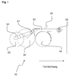
- FIGS. 1 . 2 and 3 A possible embodiment of a modular unit shescharan angel invention with independently freely pivotally arranged up coulters and separate Tiefen Operationss- and pressure arrangement is based on the FIGS. 1 . 2 and 3 illustrated.
- the arrangement has a tool carrier 50, which bends downwards in the rear part at an obtuse angle and is connected to a carrying wheel or roller 30 for depth guidance. Furthermore, the tool carrier 50 is connected via supporting connecting pieces / driving elements 56 with share arms 52.
- the coulters 40 are attached to the Schartragarmen 52, to which also the supporting connecting element / driver element 56 is mounted. This lies with the free end on the support wheel 30 bearing arm 50. If the coulter 40 is lifted by an obstacle, then the coulter 40 can escape with a pivoting movement vertically upwards. The position of the support wheel 30 is not affected by the pivotal movement of the coulter 40 and the Schartragarmes 52.
- the support arm 50, to which the carrying wheel 30 is fastened, is lifted by an obstacle, then the coulter 40 is carried along by the coupling with the entrainment element 56 in the upward movement.
- the driver element 56 limits the vertical pivoting movement of the coulters 40 down, since further movement of the coulters 40 is prevented by resting the driver element 56 on the Tragradarm 50 down.
- the support wheel 30 determines the maximum immersion depth of the coulters 40th
- a coulter 40 On the share arm 52 is a coulter 40, for example in the form of a disc coulter.
- the seed feed 42, through which the seed enters the coulter 40, is integrated into the coulter arm 52.
- the coulter arms 52 are fastened via fastening elements 53 to a coulter support element 18, for example in the form of a coulter support tube (not shown).
- a coulter support element for example in the form of a coulter support tube (not shown).
- the attachment by means of the elements 53 can be made rubber-mounted.
- the pressure roller support arms 54 are supported via lockable adjusting joints 57, on which the pressure wheels or rollers 20 are located.
- the coulter 40 prepares the seed furrow and introduces the seed fed through the seed feeder 42 into the soil.
- the support wheel 30 runs alongside or in the middle between two rows of seeds and serves for depth guidance.
- the pressure roller 20 serves to reconsolidate the soil above the seed.
- the function of the depth guide which is also carried out by the pressure wheel 20 in many conventional coulters, is not provided in a coulter arrangement according to the invention; this function is performed by the centrally running carrier roller 30.
- the pressure exerted by the pressure roller 20 on the ground pressure can be adjusted by changing the inclination of the support arm 54 via the lockable joint 57. Furthermore, the horizontal distance of the pressure wheel 20 with respect to the support wheel 30 can be changed via the lockable joint 57, so that the pressure wheel 20 either directly behind the coulter 40 or laterally offset to this runs.
- the described two ways of adjusting the positioning allow easy adjustment of the desired reconsolidation. It is thus possible with this one arrangement, the soil directly above the seed and slightly offset next to push it, furthermore, the height of the pressure used by changing the inclination of the support arm 54 can be varied as desired.
- the setting of the pressure roller 20 can, for example, be controlled by an electric motor, pneumatically or hydraulically.
- the controller can be located directly on the harrow, for example under a protective cover.
- Another possibility is the direct electronic control from the cab of the tractor (for example, the tractor).
- a mechanical adjustment and locking of the pressure rollers 20 would be a possibility for fine adjustment of the system.
Landscapes
- Life Sciences & Earth Sciences (AREA)
- Soil Sciences (AREA)
- Environmental Sciences (AREA)
- Sowing (AREA)
Priority Applications (1)
| Application Number | Priority Date | Filing Date | Title |
|---|---|---|---|
| EP07115530A EP2030496A1 (fr) | 2007-09-03 | 2007-09-03 | Agencement de coutre tracté |
Applications Claiming Priority (1)
| Application Number | Priority Date | Filing Date | Title |
|---|---|---|---|
| EP07115530A EP2030496A1 (fr) | 2007-09-03 | 2007-09-03 | Agencement de coutre tracté |
Publications (1)
| Publication Number | Publication Date |
|---|---|
| EP2030496A1 true EP2030496A1 (fr) | 2009-03-04 |
Family
ID=39060246
Family Applications (1)
| Application Number | Title | Priority Date | Filing Date |
|---|---|---|---|
| EP07115530A Withdrawn EP2030496A1 (fr) | 2007-09-03 | 2007-09-03 | Agencement de coutre tracté |
Country Status (1)
| Country | Link |
|---|---|
| EP (1) | EP2030496A1 (fr) |
Citations (10)
| Publication number | Priority date | Publication date | Assignee | Title |
|---|---|---|---|---|
| EP1060649A2 (fr) * | 1999-06-15 | 2000-12-20 | Horsch Maschinen GmbH | Semoir entraíné par un tracteur avec soc semeur et attelage trois points |
| EP1080624A1 (fr) | 1999-09-04 | 2001-03-07 | Deere & Company | Dispositif agricole pour l'épandage d'un produit |
| US6347594B1 (en) | 2000-01-28 | 2002-02-19 | Deere & Company | Narrow profile opener capable of high speed operation |
| EP1285564A1 (fr) * | 2001-08-23 | 2003-02-26 | Amazonen-Werke H. Dreyer GmbH & Co. KG | Semoir avec système hydraulique pour contrôler la profondeur |
| DE10259459A1 (de) * | 2002-12-19 | 2004-07-01 | Rabe Agrarsysteme Gmbh & Co. Kg | Sävorrichtung für Mulchsaat |
| US20040211346A1 (en) * | 2003-04-25 | 2004-10-28 | 101039130 Saskatchewan Ltd. | Dual material placing apparatus with depth adjusting pivot point |
| DE102004023087A1 (de) | 2003-06-05 | 2005-01-05 | Auf Der Landwehr Gmbh | Drillmaschine |
| DE10347142A1 (de) | 2003-10-10 | 2005-05-04 | Amazonen Werke Dreyer H | Sämaschine |
| EP1529431A1 (fr) | 2003-11-05 | 2005-05-11 | Alois Pöttinger Maschinenfabrik GmbH | Semoir |
| US20060090680A1 (en) * | 2004-11-02 | 2006-05-04 | Cnh America Llc | Suspension system for planting unit |
-
2007
- 2007-09-03 EP EP07115530A patent/EP2030496A1/fr not_active Withdrawn
Patent Citations (10)
| Publication number | Priority date | Publication date | Assignee | Title |
|---|---|---|---|---|
| EP1060649A2 (fr) * | 1999-06-15 | 2000-12-20 | Horsch Maschinen GmbH | Semoir entraíné par un tracteur avec soc semeur et attelage trois points |
| EP1080624A1 (fr) | 1999-09-04 | 2001-03-07 | Deere & Company | Dispositif agricole pour l'épandage d'un produit |
| US6347594B1 (en) | 2000-01-28 | 2002-02-19 | Deere & Company | Narrow profile opener capable of high speed operation |
| EP1285564A1 (fr) * | 2001-08-23 | 2003-02-26 | Amazonen-Werke H. Dreyer GmbH & Co. KG | Semoir avec système hydraulique pour contrôler la profondeur |
| DE10259459A1 (de) * | 2002-12-19 | 2004-07-01 | Rabe Agrarsysteme Gmbh & Co. Kg | Sävorrichtung für Mulchsaat |
| US20040211346A1 (en) * | 2003-04-25 | 2004-10-28 | 101039130 Saskatchewan Ltd. | Dual material placing apparatus with depth adjusting pivot point |
| DE102004023087A1 (de) | 2003-06-05 | 2005-01-05 | Auf Der Landwehr Gmbh | Drillmaschine |
| DE10347142A1 (de) | 2003-10-10 | 2005-05-04 | Amazonen Werke Dreyer H | Sämaschine |
| EP1529431A1 (fr) | 2003-11-05 | 2005-05-11 | Alois Pöttinger Maschinenfabrik GmbH | Semoir |
| US20060090680A1 (en) * | 2004-11-02 | 2006-05-04 | Cnh America Llc | Suspension system for planting unit |
Similar Documents
| Publication | Publication Date | Title |
|---|---|---|
| DE2140410C3 (de) | An ein ziehendes Fahrzeug anschließbare Sämaschine | |
| DE69813590T2 (de) | Pflanzeinheit | |
| DE69616283T3 (de) | Pflanzeinheit | |
| EP3026997B1 (fr) | Matériel de travail du sol muni d'un système de rappuyage | |
| EP1080624B1 (fr) | Dispositif agricole pour l'épandage d'un produit | |
| DE60112116T2 (de) | Präzisionsschälpflug mit eingebauten sähelementen | |
| EP3453238B1 (fr) | Engin agricole tracté | |
| DE2552810A1 (de) | Maschine zum ausbringen von saatgut und duengemitteln | |
| EP2158800B1 (fr) | Machine à planter des pommes de terre | |
| EP1974596B1 (fr) | Ensemble de soc semeur | |
| EP2912933A1 (fr) | Machine agricole de traitement du sol | |
| DE102008045132B4 (de) | Säscharanordnung | |
| DE102007011297B4 (de) | Gezogene Säscharanordnung | |
| EP3782443B1 (fr) | Machine de traitement du sol agricole destinée au traitement des cultures sur rang | |
| DE69404181T2 (de) | Sämaschine | |
| EP3069592B1 (fr) | Semoir | |
| DE102014223095B4 (de) | Kombination aus einem landwirtschaftlichen Zugfahrzeug und einer Direktsaat-Sämaschine | |
| DE102013214473B4 (de) | Gezogene landwirtschaftliche Maschine mit verschwenkbarer Packereinheit | |
| DE202019100926U1 (de) | Vorrichtung für eine landwirtschaftliche Maschine | |
| EP3381253A1 (fr) | Engin agricole doté d'éléments de guidage en profondeur | |
| DE102004008089A1 (de) | Sävorrichtung, insbesondere für Mulchsaat | |
| EP3127412A1 (fr) | Machine agricole destinee a traiter le sol et a extraire les semences | |
| WO2019030309A1 (fr) | Soc de semoir et semoir | |
| DE9002699U1 (de) | Bodenbearbeitungsgerät | |
| DE19954423A1 (de) | Landwirtschaftliche Bestellkombination mit günstiger Schwerpunktsverlagerung |
Legal Events
| Date | Code | Title | Description |
|---|---|---|---|
| PUAI | Public reference made under article 153(3) epc to a published international application that has entered the european phase |
Free format text: ORIGINAL CODE: 0009012 |
|
| AK | Designated contracting states |
Kind code of ref document: A1 Designated state(s): AT BE BG CH CY CZ DE DK EE ES FI FR GB GR HU IE IS IT LI LT LU LV MC MT NL PL PT RO SE SI SK TR |
|
| AX | Request for extension of the european patent |
Extension state: AL BA HR MK RS |
|
| 17P | Request for examination filed |
Effective date: 20090421 |
|
| 17Q | First examination report despatched |
Effective date: 20090609 |
|
| AKX | Designation fees paid |
Designated state(s): AT FR SE |
|
| REG | Reference to a national code |
Ref country code: DE Ref legal event code: 8566 |
|
| GRAP | Despatch of communication of intention to grant a patent |
Free format text: ORIGINAL CODE: EPIDOSNIGR1 |
|
| RIN1 | Information on inventor provided before grant (corrected) |
Inventor name: LASSEN, NIS |
|
| STAA | Information on the status of an ep patent application or granted ep patent |
Free format text: STATUS: THE APPLICATION IS DEEMED TO BE WITHDRAWN |
|
| 18D | Application deemed to be withdrawn |
Effective date: 20101113 |