EP2030816A2 - Climatisation de véhicule avec un clapet de zone arrière pour mélanger et distribuer l'air - Google Patents
Climatisation de véhicule avec un clapet de zone arrière pour mélanger et distribuer l'air Download PDFInfo
- Publication number
- EP2030816A2 EP2030816A2 EP08015377A EP08015377A EP2030816A2 EP 2030816 A2 EP2030816 A2 EP 2030816A2 EP 08015377 A EP08015377 A EP 08015377A EP 08015377 A EP08015377 A EP 08015377A EP 2030816 A2 EP2030816 A2 EP 2030816A2
- Authority
- EP
- European Patent Office
- Prior art keywords
- air
- outlet
- housing
- flap
- air conditioner
- Prior art date
- Legal status (The legal status is an assumption and is not a legal conclusion. Google has not performed a legal analysis and makes no representation as to the accuracy of the status listed.)
- Granted
Links
Images



Classifications
-
- B—PERFORMING OPERATIONS; TRANSPORTING
- B60—VEHICLES IN GENERAL
- B60H—ARRANGEMENTS OF HEATING, COOLING, VENTILATING OR OTHER AIR-TREATING DEVICES SPECIALLY ADAPTED FOR PASSENGER OR GOODS SPACES OF VEHICLES
- B60H1/00—Heating, cooling or ventilating devices
- B60H1/00007—Combined heating, ventilating, or cooling devices
- B60H1/00021—Air flow details of HVAC devices
- B60H1/00064—Air flow details of HVAC devices for sending air streams of different temperatures into the passenger compartment
-
- B—PERFORMING OPERATIONS; TRANSPORTING
- B60—VEHICLES IN GENERAL
- B60H—ARRANGEMENTS OF HEATING, COOLING, VENTILATING OR OTHER AIR-TREATING DEVICES SPECIALLY ADAPTED FOR PASSENGER OR GOODS SPACES OF VEHICLES
- B60H1/00—Heating, cooling or ventilating devices
- B60H1/00642—Control systems or circuits; Control members or indication devices for heating, cooling or ventilating devices
- B60H1/00664—Construction or arrangement of damper doors
- B60H1/00671—Damper doors moved by rotation; Grilles
-
- B—PERFORMING OPERATIONS; TRANSPORTING
- B60—VEHICLES IN GENERAL
- B60H—ARRANGEMENTS OF HEATING, COOLING, VENTILATING OR OTHER AIR-TREATING DEVICES SPECIALLY ADAPTED FOR PASSENGER OR GOODS SPACES OF VEHICLES
- B60H1/00—Heating, cooling or ventilating devices
- B60H1/00007—Combined heating, ventilating, or cooling devices
- B60H1/00021—Air flow details of HVAC devices
- B60H2001/00114—Heating or cooling details
- B60H2001/00128—Electric heaters
-
- B—PERFORMING OPERATIONS; TRANSPORTING
- B60—VEHICLES IN GENERAL
- B60H—ARRANGEMENTS OF HEATING, COOLING, VENTILATING OR OTHER AIR-TREATING DEVICES SPECIALLY ADAPTED FOR PASSENGER OR GOODS SPACES OF VEHICLES
- B60H1/00—Heating, cooling or ventilating devices
- B60H1/00007—Combined heating, ventilating, or cooling devices
- B60H1/00021—Air flow details of HVAC devices
- B60H2001/0015—Temperature regulation
- B60H2001/00164—Temperature regulation with more than one by-pass
-
- B—PERFORMING OPERATIONS; TRANSPORTING
- B60—VEHICLES IN GENERAL
- B60H—ARRANGEMENTS OF HEATING, COOLING, VENTILATING OR OTHER AIR-TREATING DEVICES SPECIALLY ADAPTED FOR PASSENGER OR GOODS SPACES OF VEHICLES
- B60H1/00—Heating, cooling or ventilating devices
- B60H1/00007—Combined heating, ventilating, or cooling devices
- B60H1/00021—Air flow details of HVAC devices
- B60H2001/00185—Distribution of conditionned air
- B60H2001/002—Distribution of conditionned air to front and rear part of passenger compartment
Definitions
- the invention relates to an air conditioning system for a motor vehicle having a housing, a heating device arranged in the housing, a plurality of air channels formed in the housing, a first outlet region formed in the housing, for supplying a first region with tempered air, and a second outlet region formed in the housing for supplying a second area with tempered air.
- the air conditioners of the prior art usually require a lot of space, kinematic couplings for the numerous flaps and high production costs for a temperature and distribution adjustment with respect to the air supply in the rear region of the motor vehicle.
- a simpler and therefore more cost-effective solution should be provided here.
- the air conditioner in its housing on an evaporator, which generates cold air to lower the interior temperature of the motor vehicle below the outside air temperature.
- a bypass channel for the warming-free passage of the cold air to the heating device, which is preferably arranged below the heating device.
- the term "below” is to be regarded in the following, the arrangement in which the air conditioner is installed in relation to the longitudinal axis of the vehicle.
- the longitudinal axis of the vehicle is arranged parallel to a longitudinal axis through the air conditioning.
- the longitudinal axis of the air conditioning is aligned transversely to the longitudinal axis of the vehicle.
- the heating device is preferably surrounded by a, an air supply to the heater preventing housing portion having an opening upstream from the heater, which is closable by a Rester michurmungsklappe. If this Resterskyrmungsklappe is closed, then the user of the motor vehicle, a maximum cooling capacity can be retrieved without this is mitigated by forcibly flowing through the heater and thereby warming air.
- an additional opening arranged upstream of the heating device for passing cold air to the second outlet region through the heating device is provided in the housing section. Through this opening, a hot air supply in the rear area regardless of the hot air supply in the front area.
- the rear compartment door is arranged in the lower region of the air conditioning system, preferably at the level of the lower edge of the heating device.
- the rear footwell supply outlet in addition to the rear ventilating outlet, preferably on both sides of the rear ventilating outlet, more preferably at substantially the same height to the rear ventilating outlet.
- the tempered air can be directed to the right and left side of the vehicle in the rear footwell.
- the rear compartment door To avoid flow losses and to avoid the unwanted mixing of different warm air, it is advantageous to divide the rear compartment door. This is preferably done by extending transversely to the axis of rotation of the rear compartment door panes, which are arranged in a central flap area and two located outside thereof, lateral flap areas. This design prevents mixing over the side flap areas to the rear footwell supply outlet directed air with the over the middle flap area conducted air.
- the middle flap region preferably has a functional web extending on the edge of the guide air vent facing the rear ventilating outlet, which extends substantially perpendicularly therefrom and essentially transversely to the direction of the hot air supply.
- the functional web is shaped like a shell, in particular adapted to the outer contour of the disks extending transversely to the axis of rotation of the rear compartment door.
- a positively coupled actuator is realized particularly cost if the middle and side flap area of the rear compartment door and the discs consist of an integral component.
- This component preferably also includes a shaft through which passes the axis of rotation of the rear compartment door. In such an embodiment takes place only a slight mixing of the amounts of air supplied to the different areas.
- the housing is divided into two along a plane in which its longitudinal axis runs. As a result, a particularly simple and quick mountability of the housing is achieved.
- a sealing device is arranged in a preferred embodiment between the Resterskyrmungsklappe and the housing portion.
- the Rester michermungsklappe is coupled with a temperature kinematics of the rear region, ie the first outlet area.
- an additional actuator can be omitted. An independent regulation of the three sections is then not possible.
- the housing has a module section in which the rear footwell supply outlet, the rear ventilation outlet and the rear compartment flap are arranged.
- the air conditioner is housed in a vehicle in which no rear space is present or the ventilation of the rear compartment is undesirable, then advantageously the area in which the module section is to be arranged, cost-effectively close by a plate or close the opening simply by spraying.
- FIG. 1 An air conditioner 1 is shown.
- the air conditioner has a housing 2.
- the housing has a portion which is referred to as module section 3.
- the module section 3 is designed in two parts along a longitudinal axis 4 of the housing 2.
- remote end of the module section 3 is a rear ventilation outlet 5 ridge-shaped channel-shaped.
- Fig. 2 is a section through the air conditioner 1 shown with the housing 2, wherein in the housing 2, a heater 7 is arranged.
- the heater 7 is supplemented by an electric heater, here a PTC heater 8.
- the heating device 7 and the PTC auxiliary heater 8 are embedded in such a way in a portion of the housing 2, that heating air only through a first opening. 9 and a second opening 10 may reach the heater 7 and the PTC heater 8.
- the first opening 9 is closed by a ResterKindlermungsklappe 11.
- a sealing device may be provided between the heat-up flap 11 and the portion of the housing 2 surrounding the heater 7.
- the heat-up flap 11 merely serves as a guide element. In this case, a leakage air flow may occur, which is also wanted in certain embodiments. Even with the restraint flap 11 closed, air can then reach the heating device 7 via the edge regions of the heat-up flap 11.
- the second opening 10 is not designed to be closable by a flap.
- air always passes through the second opening 10 to the heating device 7. The latter is heated there and subsequently exits the heating device 7 in the lower region of the air conditioning system 1.
- the air conditioning system 1 with the housing 2 is structured such that two outlet regions 12 and 13, which can be separated from one another, are present.
- the first outlet region 12 is arranged above the second outlet region 13.
- a temperature flap 14 separates the first outlet area 12 from the second outlet area 13.
- an evaporator 15 is provided, which is acted upon with fresh air L.
- the fresh air L is cooled as it passes through the evaporator, so that it is referred to as cold air K.
- the cold air K can enter the first outlet region 12 without being heated when passing through two openings. These two openings are by temperature flaps 16 and 17 closed. Alternatively, the cold air can also pass through the first opening 9 to the heating device 7, heated there and reach the first outlet region 12 when the temperature flap 14 is open.
- the cold air passing through the first opening or the cold air passing through the second opening 10 is heated by the heater 7 and / or the PTC heater 8 and thereby enters the second outlet area 13.
- the hot air W obtained may alternatively be hot - or heating air to be called.
- a bypass channel 18 is formed below the heater 7 receiving housing portion of the housing 2. Through the bypass channel 18 only cold air K, which does not exist due to the predetermined by the housing 2 separation to the heater 7 and the PTC heater 8 is heated directly. This cold air is directed in the direction of the second outlet region 13. At the far end of the second outlet area 13, the module section 3 is connected.
- the module section 3 is either integrally connected to the housing 2, glued, sprayed or otherwise connected, in the transition region of the housing 2 to the module section 3, however, the escape of air is structurally prevented.
- the module section 3 has a rear compartment door 19.
- the rear compartment door 19 extends through a rear supply area 20.
- Cold and / or warm air that enters the rear supply area 20 is via the rear ventilation outlet 5 or the two rear footwell supply outlets 6 in the rear footwell, once on the left side of the vehicle and once on the right Side of the motor vehicle, as well as in a located above the Fondfußraums area, which is referred to as a rear ventilation area made.
- Fig. 2 is the rear compartment flap area adjacent to the left rear foot space supply outlet 6, as in Fig. 1 visualized along level II.
- Fig. 2 is the rear compartment door 19 located in a position in the cold air K and hot air W from the second outlet 13 to mix a mixed stream M.
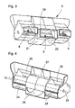
- Fig. 3 is a separate view of the module section 3 with a left rear footwell supply outlet 6 and a right rear footwell supply outlet 6. Between these Fondfußraummentssauslässen 6 a rear ventilation outlet 5 is provided.
- the module termination 3 is divided into a left half 21 and a right half 22. In the module section 3, the rear compartment door 19 is inserted.
- FIG. 4 the inserted rear compartment door 19 in the module section 3 is even better visible.
- the rear compartment door 19 is rotatably mounted about an axis of rotation 23 in the module section 3.
- the axis of rotation 23 is aligned orthogonal to the longitudinal axis 4 of the housing.
- a left rear foot room cold air area 24 and a right rear foot room cold air area 24 are provided at the outside of the module section 3 in the lower area.
- Fondfußraumkalt Kunststoff Societye 24 also outside the module section 3, Fondfußraumwarm Kunststoff Schemee 25 are provided.
- About the areas 24 and 25 cold air and / or hot air is supplied.
- a rear ventilation cold air area 26 and a rear ventilation warm air area 27 are provided. Cold and / or warm air is led to the rear ventilating outlet 5 via these two areas 26 and 27.
- the module section 3 it is possible for the module section 3 to form a dividing plane in the center in the rear ventilating outlet 5 and through the rear ventilation air and warm air areas 26, 27, so that the entire rear area is subdivided into left and right sides and can be acted upon with differently tempered air. In this way, a so-called 4-zone control can be realized inside the motor vehicle.
- FIG. 5 the rear compartment door 19 is shown with a shaft 28 which receives the axis of rotation 23.
- the rear compartment door 19 has a central flap area 29 and two lateral flap areas 30.
- the middle flap area 29 is separated from the side flap portions 30 by a respective disk 31 and 32.
- the discs 31 and 32 are perpendicular to the axis of rotation 23.
- the discs 31 and 32 are in the operating state of the inner wall of the module section 3, so that no to only small amounts of leakage air between the discs 31 and / or 32 and the adjoining surface of the Module section 3 passes through.
- the central flap region 29 has a front guide surface 33 and a rear guide surface 34.
- the lateral flap areas 30 likewise have on both sides of the shaft 28 a front guide surface 35 and a rear guide surface 36.
- the front baffle 33 and the rear baffle 34 are not in the same plane.
- the front guide surface 35 and the rear guide surface 36 are not in the same plane.
- the guide surfaces 33 to 36 are each in their own levels that are not congruent with the other three levels.
- the planes of the guide surfaces 33 to 36 are arranged on the rear compartment door 19 such that they intersect each other in the region of the axis of rotation 23.
- the rear guide surface 34 ie the guide surface which is closest to the rear ventilation outlet 5, has a functional web 37.
- the functional web 37 is perpendicular to the rear guide surface 34th
- Fig. 6a shows one half of the module section 3 with not yet installed rear compartment door 19.
- the rear compartment door 19 dashed lines in the left half of the module section 3 in Fig. 6b shown.
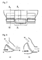
- Fig. 7 shows the position of the section lines AA and BB in the module section 3.
- FIGS. 8a . 9a, 10a and 11a the position of the lateral Flap area 30 and the FIGS. 8b . 9b, 10b and 11b reproduce the position of the middle flap area 29.
- FIGS. 8a and 8b the rear compartment door 19 is shown in a position in which cold air can neither reach the rear ventilator outlet 5 nor the rear footwell supply outlet 6. Only hot air W can get to these outlets 5 and 6.
- FIGS. 9a and 9b show a middle position of the rear compartment door 19, in which both cold air K and hot air W in the direction of the rear ventilation outlet 5 and Fondfußraummakerssauslass 6 is mixed flowing and exits there as mixed air M.
- FIGS 10a and 10b show the position of the rear compartment door 19, in which the lateral flap area 30 and the central flap area 29 prevent the supply of hot air to the rear ventilation outlet 5 and the rear foot space supply outlet 6.
- the rear guide surface 36 seals the hot air supply channel for the hot air W.
- the sealing takes place in particular by the rear guide surface 34 with the functional web 37. Only cold air K then reaches the rear ventilation outlet 5 and the rear foot space supply outlet 6.
- Fig. 11a and 11b represent the extreme position of the rear compartment door, in which any air supply, ie cold air supply K and hot air supply W, is shut off by the front guide surface and the rear guide surface 35 and 36 of the lateral flap region 30. At the same time only the hot air supply W is shut off by the front guide surface 33 and the rear guide surface 34 of the central flap region 29. From the rear footwell supply outlet 6 thus no longer passes air, whereas the maximum possible amount of cold air K exits from the rear ventilation.
- any air supply ie cold air supply K and hot air supply W
Landscapes
- Physics & Mathematics (AREA)
- Thermal Sciences (AREA)
- Engineering & Computer Science (AREA)
- Mechanical Engineering (AREA)
- Air-Conditioning For Vehicles (AREA)
Applications Claiming Priority (1)
| Application Number | Priority Date | Filing Date | Title |
|---|---|---|---|
| DE102007041689A DE102007041689A1 (de) | 2007-09-03 | 2007-09-03 | Klimaanlage für ein Kraftfahrzeug mit einer Fondraumklappe zum Mischen und Verteilen der Luft |
Publications (3)
| Publication Number | Publication Date |
|---|---|
| EP2030816A2 true EP2030816A2 (fr) | 2009-03-04 |
| EP2030816A3 EP2030816A3 (fr) | 2010-06-30 |
| EP2030816B1 EP2030816B1 (fr) | 2013-05-22 |
Family
ID=39798183
Family Applications (1)
| Application Number | Title | Priority Date | Filing Date |
|---|---|---|---|
| EP20080015377 Ceased EP2030816B1 (fr) | 2007-09-03 | 2008-09-01 | Climatisation de véhicule avec un clapet de zone arrière pour mélanger et distribuer l'air |
Country Status (2)
| Country | Link |
|---|---|
| EP (1) | EP2030816B1 (fr) |
| DE (1) | DE102007041689A1 (fr) |
Cited By (5)
| Publication number | Priority date | Publication date | Assignee | Title |
|---|---|---|---|---|
| EP3081410A3 (fr) * | 2015-04-14 | 2017-01-18 | Delphi Technologies, Inc. | Module hvac présentant une architecture ouverte |
| EP3144166A1 (fr) * | 2015-09-15 | 2017-03-22 | Mahle International GmbH | Module de chauffage, ventilation et climatisation avec commande anti-retour et procédé de fonctionnement |
| US9879870B2 (en) | 2015-04-14 | 2018-01-30 | Mahle International Gmbh | HVAC module with anti-backflow control and method of operation |
| CN112124039A (zh) * | 2020-10-20 | 2020-12-25 | 上海爱斯达克汽车空调系统有限公司 | 汽车空调进气装置 |
| EP4219200A1 (fr) * | 2022-02-01 | 2023-08-02 | Valeo Klimasysteme GmbH | Dispositif de ventilation, de chauffage et/ou de climatisation |
Families Citing this family (1)
| Publication number | Priority date | Publication date | Assignee | Title |
|---|---|---|---|---|
| DE102019128461A1 (de) * | 2019-10-22 | 2021-04-22 | Mann+Hummel Gmbh | Strömungssystem für Fluide mit einer Umschalteinrichtung |
Citations (9)
| Publication number | Priority date | Publication date | Assignee | Title |
|---|---|---|---|---|
| US4390124A (en) | 1980-02-27 | 1983-06-28 | Saab-Scania Aktiebolag | Heating and ventilation system for vehicles |
| DE69506364T2 (de) | 1994-10-28 | 1999-04-29 | Valeo Climatisation, Le Mesnil, Saint-Denis | Heizungs- und/oder Belüftungsanlage eines Fahrzeuginnenraumes |
| FR2778152A1 (fr) | 1998-04-30 | 1999-11-05 | Valeo Climatisation | Installation de chauffage, ventilation et/ou climatisation d'un habitacle, notamment de vehicule automobile, a reglage de temperature par zones |
| DE10031534A1 (de) | 1999-06-30 | 2001-01-04 | Valeo Climatisation | Innenraumheiz- und/oder Klimaanlage, insbesondere für ein Kraftfahrzeug, mit Querkanal |
| FR2795684A1 (fr) | 1999-06-30 | 2001-01-05 | Valeo Climatisation | Dispositif perfectionne de chauffage, ventilation et/ou climatisation d'un habitacle, notamment de vehicule automobile, a reglage de temperature par zones |
| EP1225071A1 (fr) | 2001-01-19 | 2002-07-24 | DENSO THERMAL SYSTEMS S.p.A. | Unité pour conditionner et distribuer l'air dans le compartiment passager d'un véhicule |
| US20040016536A1 (en) | 2002-07-23 | 2004-01-29 | Visteon Global Technologies, Inc. | HVAC system with modular inserts |
| US20050118944A1 (en) | 2003-11-28 | 2005-06-02 | Valeo Climatisation S.A. | Heating, ventilating and/or air conditioning apparatus for a motor vehicle cabin, with temperature regulation by zone |
| WO2006027219A2 (fr) | 2004-09-10 | 2006-03-16 | Behr France Rouffach Sas | Climatiseur de vehicule automobile modulaire |
Family Cites Families (5)
| Publication number | Priority date | Publication date | Assignee | Title |
|---|---|---|---|---|
| KR100294482B1 (ko) * | 1996-07-27 | 2001-10-24 | 신영주 | 공기조화장치의케이스와이를이용한공기조화장치 |
| FR2798322B1 (fr) * | 1999-09-10 | 2002-09-27 | Valeo Climatisation | Dispositif de chauffage et/ou climatisation de vehicule automobile a distribution amelioree |
| JP3952919B2 (ja) * | 2002-09-17 | 2007-08-01 | 株式会社デンソー | 車両用空調装置 |
| JP4085769B2 (ja) * | 2002-10-11 | 2008-05-14 | 株式会社デンソー | 車両用空調装置 |
| US8474513B2 (en) * | 2004-06-24 | 2013-07-02 | Behr Gmbh & Co. Kg | Air-conditioning system, especially automotive air-conditioning system |
-
2007
- 2007-09-03 DE DE102007041689A patent/DE102007041689A1/de not_active Withdrawn
-
2008
- 2008-09-01 EP EP20080015377 patent/EP2030816B1/fr not_active Ceased
Patent Citations (10)
| Publication number | Priority date | Publication date | Assignee | Title |
|---|---|---|---|---|
| US4390124A (en) | 1980-02-27 | 1983-06-28 | Saab-Scania Aktiebolag | Heating and ventilation system for vehicles |
| DE69506364T2 (de) | 1994-10-28 | 1999-04-29 | Valeo Climatisation, Le Mesnil, Saint-Denis | Heizungs- und/oder Belüftungsanlage eines Fahrzeuginnenraumes |
| FR2778152A1 (fr) | 1998-04-30 | 1999-11-05 | Valeo Climatisation | Installation de chauffage, ventilation et/ou climatisation d'un habitacle, notamment de vehicule automobile, a reglage de temperature par zones |
| DE10031534A1 (de) | 1999-06-30 | 2001-01-04 | Valeo Climatisation | Innenraumheiz- und/oder Klimaanlage, insbesondere für ein Kraftfahrzeug, mit Querkanal |
| FR2795684A1 (fr) | 1999-06-30 | 2001-01-05 | Valeo Climatisation | Dispositif perfectionne de chauffage, ventilation et/ou climatisation d'un habitacle, notamment de vehicule automobile, a reglage de temperature par zones |
| EP1225071A1 (fr) | 2001-01-19 | 2002-07-24 | DENSO THERMAL SYSTEMS S.p.A. | Unité pour conditionner et distribuer l'air dans le compartiment passager d'un véhicule |
| US20040016536A1 (en) | 2002-07-23 | 2004-01-29 | Visteon Global Technologies, Inc. | HVAC system with modular inserts |
| US20050118944A1 (en) | 2003-11-28 | 2005-06-02 | Valeo Climatisation S.A. | Heating, ventilating and/or air conditioning apparatus for a motor vehicle cabin, with temperature regulation by zone |
| FR2862911A1 (fr) | 2003-11-28 | 2005-06-03 | Valeo Climatisation | Dispositif de chauffage-ventilation et/ou climatisation d'un habitacle de vehicule avec reglage de temperature par zones |
| WO2006027219A2 (fr) | 2004-09-10 | 2006-03-16 | Behr France Rouffach Sas | Climatiseur de vehicule automobile modulaire |
Cited By (7)
| Publication number | Priority date | Publication date | Assignee | Title |
|---|---|---|---|---|
| EP3081410A3 (fr) * | 2015-04-14 | 2017-01-18 | Delphi Technologies, Inc. | Module hvac présentant une architecture ouverte |
| US9724978B2 (en) | 2015-04-14 | 2017-08-08 | Mahle International Gmbh | HVAC module having an open architecture |
| US9879870B2 (en) | 2015-04-14 | 2018-01-30 | Mahle International Gmbh | HVAC module with anti-backflow control and method of operation |
| EP3144166A1 (fr) * | 2015-09-15 | 2017-03-22 | Mahle International GmbH | Module de chauffage, ventilation et climatisation avec commande anti-retour et procédé de fonctionnement |
| CN112124039A (zh) * | 2020-10-20 | 2020-12-25 | 上海爱斯达克汽车空调系统有限公司 | 汽车空调进气装置 |
| EP4219200A1 (fr) * | 2022-02-01 | 2023-08-02 | Valeo Klimasysteme GmbH | Dispositif de ventilation, de chauffage et/ou de climatisation |
| WO2023148239A1 (fr) * | 2022-02-01 | 2023-08-10 | Valeo Klimasysteme Gmbh | Dispositif de ventilation, chauffage et/ou climatisation |
Also Published As
| Publication number | Publication date |
|---|---|
| EP2030816B1 (fr) | 2013-05-22 |
| EP2030816A3 (fr) | 2010-06-30 |
| DE102007041689A1 (de) | 2009-03-05 |
Similar Documents
| Publication | Publication Date | Title |
|---|---|---|
| DE60225979T3 (de) | Vorrichtung zur Erzeugung einer temperaturgeregelten Luftströmung für einen Kraftfahrzeugfahrgastraum und Heizungs- und/oder Klimaanlage mit einer solchen Steuerungsvorrichtung | |
| EP1902876B1 (fr) | Boîtier de distribution d'air, en particulier pour une climatisation de véhicule, le boîtier comprenant une vanne de distribution et un procédé de contrôle d'une telle vanne de distribution | |
| EP2030816B1 (fr) | Climatisation de véhicule avec un clapet de zone arrière pour mélanger et distribuer l'air | |
| DE102015110481A1 (de) | Vorrichtung zum Beheizen, Belüften und/oder Klimatisieren eines Fahrzeuginnenraums | |
| DE102021209994A1 (de) | Klimaanlage eines Kraftfahrzeugs | |
| EP1761406B1 (fr) | Climatiseur, en particulier climatiseur de vehicule automobile | |
| DE102017218343A1 (de) | Verfahren zur verteilung von luftventilation in einem fahrzeug | |
| DE19804287C1 (de) | Klimaanlage für Fahrzeuge | |
| EP1634735B2 (fr) | Appareil de climatisation modulaire pour véhicule | |
| EP2011675B1 (fr) | Climatiseur | |
| EP1641642A1 (fr) | Volet de boitier de guidage d'air pour un systeme de climatisation de vehicule a moteur | |
| EP2048010B1 (fr) | Agencement de climatisation de véhicule automobile | |
| DE102004056813B4 (de) | Mehrzonen-Klimaanlage | |
| EP1761405B1 (fr) | Climatiseur, en particulier climatiseur de vehicule automobile | |
| DE10031534B4 (de) | Innenraumheiz- und/oder Klimaanlage, insbesondere für ein Kraftfahrzeug, mit Querkanal | |
| DE102007049340A1 (de) | Kraftfahrzeug-Klimaanlagenanordnung | |
| DE19756166B4 (de) | Luftkanal für eine Heizungs- oder Klimaanlage eines Kraftfahrzeuges sowie damit ausgerüstete Heizungs- oder Klimaanlage | |
| EP2011676B1 (fr) | Climatiseur | |
| DE102004030672B4 (de) | V-förmige Wärmetauscheranordnung einer Heiz-Klimaanlage | |
| EP1972473B1 (fr) | Climatisation pour un véhicule automobile | |
| EP1531067B1 (fr) | Système de conditionnement d'air en particulier pour véhicule | |
| EP1733904B1 (fr) | Dispositif de climatisation pour véhicule comprenant une dérivation à air froid | |
| EP1555148B1 (fr) | Dispositif de climatisation, en particulier pour un véhicule | |
| DE102006027996A1 (de) | Klimaanlage mit Kaltluft-Bypass, insbesondere für ein Kraftfahrzeug | |
| EP1792761B1 (fr) | Installation des volets |
Legal Events
| Date | Code | Title | Description |
|---|---|---|---|
| PUAI | Public reference made under article 153(3) epc to a published international application that has entered the european phase |
Free format text: ORIGINAL CODE: 0009012 |
|
| AK | Designated contracting states |
Kind code of ref document: A2 Designated state(s): AT BE BG CH CY CZ DE DK EE ES FI FR GB GR HR HU IE IS IT LI LT LU LV MC MT NL NO PL PT RO SE SI SK TR |
|
| AX | Request for extension of the european patent |
Extension state: AL BA MK RS |
|
| PUAL | Search report despatched |
Free format text: ORIGINAL CODE: 0009013 |
|
| AK | Designated contracting states |
Kind code of ref document: A3 Designated state(s): AT BE BG CH CY CZ DE DK EE ES FI FR GB GR HR HU IE IS IT LI LT LU LV MC MT NL NO PL PT RO SE SI SK TR |
|
| AX | Request for extension of the european patent |
Extension state: AL BA MK RS |
|
| 17P | Request for examination filed |
Effective date: 20101230 |
|
| AKX | Designation fees paid |
Designated state(s): DE FR GB |
|
| 17Q | First examination report despatched |
Effective date: 20111223 |
|
| GRAP | Despatch of communication of intention to grant a patent |
Free format text: ORIGINAL CODE: EPIDOSNIGR1 |
|
| GRAS | Grant fee paid |
Free format text: ORIGINAL CODE: EPIDOSNIGR3 |
|
| GRAA | (expected) grant |
Free format text: ORIGINAL CODE: 0009210 |
|
| AK | Designated contracting states |
Kind code of ref document: B1 Designated state(s): DE FR GB |
|
| REG | Reference to a national code |
Ref country code: GB Ref legal event code: FG4D Free format text: NOT ENGLISH |
|
| RIN1 | Information on inventor provided before grant (corrected) |
Inventor name: OTZELBERGER, NORBERT Inventor name: LINDAUER, SASCHA Inventor name: BURKHARDT, CARSTEN Inventor name: SCHWEIZER, GEBHARD |
|
| REG | Reference to a national code |
Ref country code: DE Ref legal event code: R096 Ref document number: 502008009963 Country of ref document: DE Effective date: 20130718 |
|
| PLBE | No opposition filed within time limit |
Free format text: ORIGINAL CODE: 0009261 |
|
| STAA | Information on the status of an ep patent application or granted ep patent |
Free format text: STATUS: NO OPPOSITION FILED WITHIN TIME LIMIT |
|
| 26N | No opposition filed |
Effective date: 20140225 |
|
| GBPC | Gb: european patent ceased through non-payment of renewal fee |
Effective date: 20130901 |
|
| REG | Reference to a national code |
Ref country code: DE Ref legal event code: R097 Ref document number: 502008009963 Country of ref document: DE Effective date: 20140225 |
|
| PG25 | Lapsed in a contracting state [announced via postgrant information from national office to epo] |
Ref country code: GB Free format text: LAPSE BECAUSE OF NON-PAYMENT OF DUE FEES Effective date: 20130901 |
|
| REG | Reference to a national code |
Ref country code: DE Ref legal event code: R082 Ref document number: 502008009963 Country of ref document: DE Representative=s name: GRAUEL, ANDREAS, DIPL.-PHYS. DR. RER. NAT., DE |
|
| REG | Reference to a national code |
Ref country code: DE Ref legal event code: R081 Ref document number: 502008009963 Country of ref document: DE Owner name: MAHLE INTERNATIONAL GMBH, DE Free format text: FORMER OWNER: BEHR GMBH & CO. KG, 70469 STUTTGART, DE Effective date: 20150323 Ref country code: DE Ref legal event code: R082 Ref document number: 502008009963 Country of ref document: DE Representative=s name: GRAUEL, ANDREAS, DIPL.-PHYS. DR. RER. NAT., DE Effective date: 20150323 |
|
| REG | Reference to a national code |
Ref country code: FR Ref legal event code: PLFP Year of fee payment: 9 |
|
| REG | Reference to a national code |
Ref country code: FR Ref legal event code: PLFP Year of fee payment: 10 |
|
| REG | Reference to a national code |
Ref country code: FR Ref legal event code: PLFP Year of fee payment: 11 |
|
| PGFP | Annual fee paid to national office [announced via postgrant information from national office to epo] |
Ref country code: DE Payment date: 20181001 Year of fee payment: 11 |
|
| PGFP | Annual fee paid to national office [announced via postgrant information from national office to epo] |
Ref country code: FR Payment date: 20190925 Year of fee payment: 12 |
|
| REG | Reference to a national code |
Ref country code: DE Ref legal event code: R119 Ref document number: 502008009963 Country of ref document: DE |
|
| PG25 | Lapsed in a contracting state [announced via postgrant information from national office to epo] |
Ref country code: DE Free format text: LAPSE BECAUSE OF NON-PAYMENT OF DUE FEES Effective date: 20200401 |
|
| PG25 | Lapsed in a contracting state [announced via postgrant information from national office to epo] |
Ref country code: FR Free format text: LAPSE BECAUSE OF NON-PAYMENT OF DUE FEES Effective date: 20200930 |