EP2030883A1 - Kraftstofftankanordnung für ein Motorrad und mit einer solchen Tankanordnung ausgestattetes Motorrad - Google Patents
Kraftstofftankanordnung für ein Motorrad und mit einer solchen Tankanordnung ausgestattetes Motorrad Download PDFInfo
- Publication number
- EP2030883A1 EP2030883A1 EP07017224A EP07017224A EP2030883A1 EP 2030883 A1 EP2030883 A1 EP 2030883A1 EP 07017224 A EP07017224 A EP 07017224A EP 07017224 A EP07017224 A EP 07017224A EP 2030883 A1 EP2030883 A1 EP 2030883A1
- Authority
- EP
- European Patent Office
- Prior art keywords
- assembly
- fuel
- fuel tank
- motorcycle
- recess
- Prior art date
- Legal status (The legal status is an assumption and is not a legal conclusion. Google has not performed a legal analysis and makes no representation as to the accuracy of the status listed.)
- Granted
Links
Images


Classifications
-
- B—PERFORMING OPERATIONS; TRANSPORTING
- B62—LAND VEHICLES FOR TRAVELLING OTHERWISE THAN ON RAILS
- B62J—CYCLE SADDLES OR SEATS; AUXILIARY DEVICES OR ACCESSORIES SPECIALLY ADAPTED TO CYCLES AND NOT OTHERWISE PROVIDED FOR, e.g. ARTICLE CARRIERS OR CYCLE PROTECTORS
- B62J35/00—Fuel tanks specially adapted for motorcycles or engine-assisted cycles; Arrangements thereof
-
- B—PERFORMING OPERATIONS; TRANSPORTING
- B62—LAND VEHICLES FOR TRAVELLING OTHERWISE THAN ON RAILS
- B62J—CYCLE SADDLES OR SEATS; AUXILIARY DEVICES OR ACCESSORIES SPECIALLY ADAPTED TO CYCLES AND NOT OTHERWISE PROVIDED FOR, e.g. ARTICLE CARRIERS OR CYCLE PROTECTORS
- B62J23/00—Other protectors specially adapted for cycles
Definitions
- the present invention relates to a fuel tank assembly for a motorcycle and a respective motorcycle comprising such a fuel tank assembly.
- the fuel pumps usually used, comprise a collecting portion adapted to collect fuel from the fuel tank, along with a delivering portion adapted to deliver the collected fuel to the injection system of the motorcycle.
- the fuel pipes is provided, extending from said delivering portion of the fuel tank to said injection system of the motorcycle.
- the collecting portion of the fuel pump is usually located inside the fuel tank, whilst the delivering portion and the fuel pipe extending therefrom are usually placed outside the fuel tank.
- finding a convenient location for the delivering portion of the fuel pump and the fuel pipe extending therefrom has revealed to be a difficult task; in particular, this is due to the fact that the location of the delivering portion of the fuel pump not only influences the overall layout of the motorcycle, but also the performances of the fuel pump, which strongly depend on the location of the delivering portion.
- motorcycles usually comprise covering elements mounted to the motorcycle for improving both the aerodynamics and the overall appearance or design of the motorcycle.
- these covering elements in some cases are provided to cover or protect mechanical components of the motorcycle such as, for instance, the engine, but also to cover or protect at least partially the fuel tank of the motorcycle.
- the fuel pump or at least the collecting portion thereof is located below the fuel tank; in particular, in some cases, said delivering portion is mounted to the bottom wall of the fuel tank. In more detail, said delivering portion is screwed on a corresponding aperture formed in the bottom wall of the fuel tank.
- other component parts of the motorcycle such as for instance, the injection system or at least the air filter thereof are also located below the fuel tank. Accordingly, the assembling operations might become troublesome and/or difficult, resulting in the time required for the assembly operations being unduly elongated and the corresponding costs being unduly increased.
- the solutions proposed in the past and known in the prior art do not meet all the essential requirements which have to be taken into consideration during the design of a motorcycle.
- the proposed solutions do not meet the need of a fuel tank assembly wherein the fuel pump is located at a convenient position allowing to offer good performance in terms of functionality and easy assembly and/or maintenance, as well as in terms of the overall look and appearance of the motorcycle.
- a fuel tank assembly for a motorcycle, with said assembly comprising a fuel tank and a fuel pump, wherein said fuel pump is located at a position with respect to the fuel tank such as to offer adequate performance in terms of functionality, easy assembly and maintenance, but without negatively affecting other important criteria and/or requirements, such as, for instance the overall dimensions and/or the external look of the motorcycle.
- the present invention is based on the consideration that the problems affecting the prior art layouts relating to the fuel tank assembly may be overcome by mounting the fuel pump or at least the delivering portion thereof on the top of the fuel tank, in particular on the top wall of the fuel tank.
- a further consideration on which the present invention is based relates to the fact that, when this layout is selected, in particular when this location for the fuel pump or at least the delivering portion thereof is selected, also the fuel pipe may be conveniently arranged, in spite of its increased length due to the increased distance between the fuel pump or at least the delivering portion thereof and the injection system of the motorcycle.
- a further consideration on which the present invention is based relates to the fact that, by opportunely arranging at least the fuel pipe with respect to the fuel tank or at least by opportunely fixing at least said fuel pipe to the fuel tank, adequate covering means may be mounted on at least said fuel tank without negatively affecting the overall dimensions and look of the motorcycle.
- the present invention is understood to be of particular advantage when applied to two-wheeled motorcycles, such as, for instance, motorbikes. For this reason, examples will be given in the following, in which corresponding embodiments of the fuel tank assembly according to the present invention are applied to motorbikes.
- the applications of the fuel tank assembly according to the present invention are not limited to the case of motorbikes.
- the fuel tank assembly according to the present invention may also be applied to other motorcycles, in particular to three or even four-wheeled motorcycles such as for instance, choppers, quads, or the like.
- FIG 1 a motorcycle 100 is depicted. Although some portions or component parts common to usual motorcycles have been omitted in Figure 1 for the sake of clarity, the essential features of common motorcycles have been depicted in Figure 1 and relate in particular to a fuel tank assembly 1 comprising a cover or covering element 8 covering or protecting a fuel tank (which has therefore to be understood as being located below said covering element 8). Further side covering elements 112 are mounted to the motorcycle 100 on opposite sides thereof; components of the motorcycle such as, for instance, the crankcase, the cylinder or the like have therefore to be understood as being located in the area defined by said side covering elements, in combination, and therefore as being located behind the right side cover element 112 depicted in Figure 1 .
- a fuel tank assembly 1 comprising a cover or covering element 8 covering or protecting a fuel tank (which has therefore to be understood as being located below said covering element 8).
- Further side covering elements 112 are mounted to the motorcycle 100 on opposite sides thereof; components of the motorcycle such as, for instance, the crankcase, the cylinder or the like have therefore
- a front cowling element 140 is located at the front end portion of the motorcycle 100, with said front cowling element 140 comprising and/or supporting components such as, for instance, headlights, front direction indicators, rear mirrors, speedometer or the like.
- a front wheel 116 comprising a brake disk 116bd is supported by a front fork 115, with said front wheel 116 being attached to said front fork 115 by means of a front axle 116a.
- the motorcycle 100 further comprises a rear wheel 120 with a sprocket 125, a chain 124 being further provided to transmit drive force to the rear wheel 120 through the rear sprocket 125.
- reference numeral 122 identifies a handlebar provided with brake handles and corresponding cables extending therefrom.
- reference numeral 123 identifies a front fender provided to avoid the motorcycle 100 and the driver and/or passenger being splashed with mud.
- Reference numeral 130 identifies a silencer belonging to an exhaust gas apparatus extending from the cylinder to the rear of the motorcycle (therefore partially covered in Figure 1 by the sidecover element 112).
- a seat 118 is further provided, with said seat 118 being placed behind the fuel assembly 1, in particular behind the cover 8 and the fuel tank located below or under said cover 8.
- the motorcycle or Figure 1 comprises an injection system generally identified in Figure 1 by reference numeral 101.
- the injection system 101 of the motorcycle depicted therein is located in the area below the fuel tank assembly 1, in particular below the fuel tank located below the fuel tank cover 8 and therefore not explicitly depicted in Figure 1 .
- the fuel tank assembly 1 further comprises a fuel pump (not depicted in Figure 1 ), adapted to collect fuel from the fuel tank and to deliver same to the injection system 101; at least one fuel pipe is also provided, extending from the fuel pump to the injection system 101.
- the fuel tank assembly 1 comprises a fuel tank 2 adapted to be filled with fuel through an aperture 2c; the aperture 2c is moreover adapted to be closed by means of a cap or plug (not depicted in the drawings), said cap or plug being further adapted to be removed from the aperture 2c any time the need arises to fill the tank 2 with fuel.
- the cap or plug may comprise a screw plug or the like, eventually comprising a locking device with a key.
- a fuel pump 3 is also provided, adapted to collect fuel from the fuel tank 2 and to deliver the collected fuel to the injection system 101 of the motorcycle 100.
- the fuel pump 3 comprises a collecting portion 3a received inside the fuel tank 2 and a delivering portion 3b in fluid connection with said collecting portion 3a; in particular, as apparent from Figures 3A and 2 , said delivering portion 3b is mounted to the upper wall 2a of the fuel tank 2.
- This particular location of the delivering portion 3b of the fuel pump 3 allows to overcome many of the drawbacks affecting the prior art fuel tank assemblies; in fact, mounting the delivering portion 3b to the upper wall 2a of the fuel tank 2 allows to overcome the problems relating to leakage of fuels which arise in those cases in which the delivering portion of the fuel pump is mounted to the bottom wall of the fuel tank.
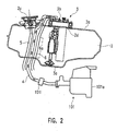
- a fuel pipe 4 extends from the receiving portion 3b of the fuel pump 3 to the injection system 101 (see also Figure 2 ) so as to establish a fluid connection between said delivering portion 3b of said fuel pump 3 and said injection system 101.
- said injection system 101 may comprise a fuel injector 101 i and an air filter 101 a (see for example Figure 2 ); however, it has to be noted that the injection system falls outside the scope of the present invention so that further details relating to said injection system may be avoided.
- At least one electrical cable 6 is also provided for the purpose of supplying electrical power to the fuel pump 3; in particular, as apparent from Figure 2 , a first end portion of said electrical cable 6 is connected to the delivering portion 3b of said fuel pump 3 with said electrical cable 6 extending from said delivering portion 3b.
- said electrical cable 6 is adapted to be connected through a second end portion opposite to said first end portion to either the battery or to an electrical control unit or the like of the motorcycle.
- FIG. 2 shows that at least a portion 6a of said electrical cable 6 extends beside the fuel pipe 4; this disposition of the fuel pipe 4 and/or the electrical cable 6 offers further advantages in terms of the overall layout of the motorcycle, as will become more apparent with the following disclosure.
- the embodiment of the present invention depicted in Figures 2 , 3A , and 3B further comprises an overflow pipe 5 extending from a collecting basin 5b; during use of the motorcycle and in case of fuel overflowing from the fuel tank 2 through the aperture 2c, the overflowing fuel may be collected by the collecting basin 5b and delivered through the overflow pipe 5 to a overflowing system (not depicted in the drawings) from which the overflowing fuel is filled again into the fuel tank 2.
- a overflowing system not depicted in the drawings
- overflow pipe 5 or at least a portion 5a thereof extends beside the fuel pipe 4 and the electrical cable 6.
- the advantages arising from this particular disposition of the overflow pipe 5, the fuel pipe 4, and the electrical cable 6 will be disclosed in more detail in the following.
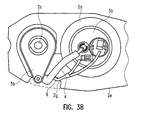
- the fuel tank 2 further comprises a side wall 2e extending downward from said upper wall 2a; in particular, said side wall 2e defines a recess 2g wherein at least portions 5a, 4a and 6a of said overflow pipe 5, said fuel pipe 4, and said electrical cable 6, respectively, are received.
- Said recess 2g extends between said upper wall 2a and a bottom wall of said fuel tank 2 (see in particular Figure 2 ).
- said recess 2g extends from said upper wall 2a to the bottom wall of the fuel tank 2 in a direction substantially vertical; however, it has to be noted that also other solutions are possible according to the circumstances.
- the recess 2g may extend at an angle between the upper wall 2a and the bottom wall of the fuel tank 2.
- the recess 2g further extends from the side wall 2e toward the inside of the fuel tank 2 (toward the top in Figure 3b ) for a predefined depth; in particular, according to the embodiment depicted in Figure 3b , the depth of the recess 2g may be selected so as to allow said portions 6a, 5a and 4a of said electrical cable 6, said overflow pipe 5 and said fuel pipe 4 to be received inside said recess 2g so as to not extend beyond the side wall 2e of said fuel tank 2 (see in particular the dashed line in Figure 3b ).
- disposing the electrical cable 6, the fuel pipe 4 and the overflow pipe 5 inside the recess 2g of the sidewall 2e of the fuel tank 2 allows to mount a cover or covering element to the fuel tank 2, with said cover or covering element matching with the external dimensions and shape of the fuel tank 2; that means that no additional space is needed for disposing the fuel pipe 4, the electrical cable 6 and the overflow pipe 5 between the fuel tank 2 and said cover 8.
- FIG 3C relates to particular details of the fuel tank 2 belonging to the fuel tank assembly 1 of the present invention.
- fixing means are mounted to the fuel tank 2 inside the recess 2g defined by its side wall 2e.
- said fixing means comprise a membrane or blade 7, extending in a direction substantially transverse to the direction along which the recess 2g extends.
- said membrane 7 comprises indentations or notches 7a, 7b and 7c, the dimension and shape of which are selected so as to allow the overflow pipe 5, the fuel pipe 4 and the electrical cable 6 to be elastically forced into said indentations 7a, 7b and 7c, respectively.
- These indentations allow to avoid movement or displacement of the overflow pipe 5, the fuel pipe 4 and the electrical cable 6 during use of the motorcycle, for instance due to vibrations or the like.
- the elastic membrane 7 it may be avoided that the overflow pipe 6, the fuel pipe 4 and the electrical cable 6 come outside of the recess 2g so as to extend beyond the side wall 2e of the fuel tank 2.
- a cover or covering element 8 is depicted.
- said cover or covering element 8 is adapted to be mounted to the fuel tank 2 so as to cover said fuel tank 2 at least partially.
- the cover 8 comprises a trough aperture 8f adapted to be located in correspondence to the aperture 2c of the fuel tank 2, once said cover 8 has been mounted to said fuel tank 2.
- the cover 8 comprises fixing means 8e adapted to cooperate with corresponding fixing means 8e2 of said fuel tank 2 so as to allow said cover 8 to be firmly fixed to said fuel tank 2.
- the cover 8 may be fixed to the fuel tank 2 by means of screwing means such as, screws, bolts or the like, received into corresponding apertures of the fixing means 8e and 8e2.
- the cover element 8 comprises a central portion 8a wherein the trough aperture 8f is provided.
- said central portion 8a is adapted to cover, once said cover element 8 has been mounted to said fuel tank 2, at least the upper wall 2a of the fuel tank 2 and the delivering portion 3b of the fuel pump 3 mounted to said upper wall 2a of said fuel tank 2.
- the cover 8 further comprises, as apparent from Figure 5A , a first side portion 8b extending downward from said central portion 8a; it appears clearly from Figure 5A , that said first side portion 8b is adapted to cover at least partially said side wall 2e of said fuel tank 2 once said cover 8 has been mounted to said fuel tank 2.
- the side portion 8b of the cover 8 is adapted to cover at least partially the recess 2g defined by the side wall 2e of the fuel tank 2 and at least portions 6a, 5a and 4a of said electrical cable 6, said overflow pipe 5 and said fuel pipe 4, respectively, received inside said recess 2g.
- the length or extension in the substantially vertical direction of the side portion 8b of the cover 8 may be selected according to the circumstances and/ exigencies; for instance, it may be provided that the side portion 8b of the cover 8 extends to a length such that the recess 2g defined by the lateral wall 2e and the fuel pipe 4, the overflow pipe 5 and the electrical cable 6 or portions thereof received inside said recess 2g are substantially completely covered by said side portion 8b once said cover 8 has been mounted to said fuel tank 2.
- the cover 8 comprises a second side portion 8c extending downward from said central portion 8a and being located opposite said first side portion 8b; similarly to the case of the side portion 8b, the length or extension of the side portion 8c downward from said central portion 8a may be selected according to the circumstances and/or exigencies.
- the fuel tank 2 comprises fixing means 2f adapted to firmly fix said fuel tank 2 to the motorcycle 1, for instance to the chassis or main frame thereof.
- screwing means such as screws, bolts or the like may be used, with said screwing means being received into an aperture of said fixing means 2f.
- the side portions 8b and 8c of the cover element depicted therein are adapted to be alternatively fixed to and removed from said central portion 8a; to this end, connecting means 8d are provided on the edges of said side portions 8d and 8c facing said central portion 8a, as well as on the opposite edges of said central portion 8a facing said side portions 8b and 8c, respectively.
- the number and kind of said connecting means may be selected according to the circumstances; for instance, clips or the like may be provided.
- the solution depicted in Figure 6 allows to simplify and speed up both the assembly and maintenance operation. For instance, when the need arises to gain access to the delivering portion 3b of the fuel pump, only the central portion 8a of the cover 8 may be removed.
- the fuel tank assembly according to the present invention allows the drawbacks affecting the prior art fuel tank assemblies to be overcome or at least reduced or minimized.
- the fuel tank assembly according to the present invention offers evident advantages in terms of functionality and design. It has in fact been demonstrated that the particular location of the fuel pump, in particular of the delivering portion thereof on the upper portion or wall of the fuel tank allows using tanks of plastic or equivalent materials without any risk of fuel leakages being run. Moreover, disposing the fuel pump or at least the delivering portion thereof on the upper portion or wall of the fuel tank allows to simplify and speed up the assembly and/or maintenance operations with corresponding evident advantages in terms of reduced assembly and maintenance costs.
- fuel tanks of different shapes and dimensions may be implemented and used in the fuel tank assembly according to the present invention.
- fuel tanks having a substantially rounded shape or at least a substantially rounded upper portion or wall may also be implemented in the fuel tank assembly of the present invention according to the circumstances and/or exigencies and without departing from the scope of the present invention.
Landscapes
- Engineering & Computer Science (AREA)
- Mechanical Engineering (AREA)
- Cooling, Air Intake And Gas Exhaust, And Fuel Tank Arrangements In Propulsion Units (AREA)
- Automatic Cycles, And Cycles In General (AREA)
Priority Applications (6)
| Application Number | Priority Date | Filing Date | Title |
|---|---|---|---|
| ES09015081.4T ES2545882T3 (es) | 2007-09-03 | 2007-09-03 | Conjunto de depósito de carburante para una motocicleta y una motocicleta equipada con dicho conjunto de depósito de carburante |
| AT07017224T ATE456505T1 (de) | 2007-09-03 | 2007-09-03 | Kraftstofftankanordnung für ein motorrad und mit einer solchen tankanordnung ausgestattetes motorrad |
| EP09015081.4A EP2165921B1 (de) | 2007-09-03 | 2007-09-03 | Kraftstofftankanordnung für ein Motorrad und mit einer solchen Tankanordnung ausgestattetes Motorrad |
| EP07017224A EP2030883B1 (de) | 2007-09-03 | 2007-09-03 | Kraftstofftankanordnung für ein Motorrad und mit einer solchen Tankanordnung ausgestattetes Motorrad |
| DE602007004606T DE602007004606D1 (de) | 2007-09-03 | 2007-09-03 | Kraftstofftankanordnung für ein Motorrad und mit einer solchen Tankanordnung ausgestattetes Motorrad |
| ES07017224T ES2338816T3 (es) | 2007-09-03 | 2007-09-03 | Conjunto de deposito de carburante para una motocicleta y una motocicleta equipada con dicho conjunto de deposito de carburante. |
Applications Claiming Priority (1)
| Application Number | Priority Date | Filing Date | Title |
|---|---|---|---|
| EP07017224A EP2030883B1 (de) | 2007-09-03 | 2007-09-03 | Kraftstofftankanordnung für ein Motorrad und mit einer solchen Tankanordnung ausgestattetes Motorrad |
Related Child Applications (2)
| Application Number | Title | Priority Date | Filing Date |
|---|---|---|---|
| EP09015081.4A Division-Into EP2165921B1 (de) | 2007-09-03 | 2007-09-03 | Kraftstofftankanordnung für ein Motorrad und mit einer solchen Tankanordnung ausgestattetes Motorrad |
| EP09015081.4A Division EP2165921B1 (de) | 2007-09-03 | 2007-09-03 | Kraftstofftankanordnung für ein Motorrad und mit einer solchen Tankanordnung ausgestattetes Motorrad |
Publications (2)
| Publication Number | Publication Date |
|---|---|
| EP2030883A1 true EP2030883A1 (de) | 2009-03-04 |
| EP2030883B1 EP2030883B1 (de) | 2010-01-27 |
Family
ID=38962861
Family Applications (2)
| Application Number | Title | Priority Date | Filing Date |
|---|---|---|---|
| EP09015081.4A Active EP2165921B1 (de) | 2007-09-03 | 2007-09-03 | Kraftstofftankanordnung für ein Motorrad und mit einer solchen Tankanordnung ausgestattetes Motorrad |
| EP07017224A Active EP2030883B1 (de) | 2007-09-03 | 2007-09-03 | Kraftstofftankanordnung für ein Motorrad und mit einer solchen Tankanordnung ausgestattetes Motorrad |
Family Applications Before (1)
| Application Number | Title | Priority Date | Filing Date |
|---|---|---|---|
| EP09015081.4A Active EP2165921B1 (de) | 2007-09-03 | 2007-09-03 | Kraftstofftankanordnung für ein Motorrad und mit einer solchen Tankanordnung ausgestattetes Motorrad |
Country Status (4)
| Country | Link |
|---|---|
| EP (2) | EP2165921B1 (de) |
| AT (1) | ATE456505T1 (de) |
| DE (1) | DE602007004606D1 (de) |
| ES (2) | ES2545882T3 (de) |
Cited By (6)
| Publication number | Priority date | Publication date | Assignee | Title |
|---|---|---|---|---|
| US8505592B2 (en) | 2010-09-20 | 2013-08-13 | Honda Motor Company, Ltd. | Fuel spill tray |
| JP2014088082A (ja) * | 2012-10-30 | 2014-05-15 | Honda Motor Co Ltd | 鞍乗型車両における収納構造 |
| CN104276236A (zh) * | 2014-09-10 | 2015-01-14 | 重庆隆鑫机车有限公司 | 油箱及其摩托车 |
| CN112512853A (zh) * | 2018-10-25 | 2021-03-16 | 宝马股份公司 | 用于摩托车的燃料箱固定组件以及摩托车组件 |
| JPWO2022070519A1 (de) * | 2020-09-30 | 2022-04-07 | ||
| JP2022120922A (ja) * | 2021-02-08 | 2022-08-19 | 本田技研工業株式会社 | 鞍乗型車両 |
Families Citing this family (9)
| Publication number | Priority date | Publication date | Assignee | Title |
|---|---|---|---|---|
| JP5766446B2 (ja) * | 2011-01-18 | 2015-08-19 | 本田技研工業株式会社 | 燃料タンクカバー構造 |
| WO2013148848A1 (en) * | 2012-03-28 | 2013-10-03 | Salvaggio David Jr | Carbon fiber shells for customizing the appearance of a vehicle |
| US11230338B2 (en) | 2012-03-28 | 2022-01-25 | Salvaggio Jr David | Integrated electronic component in vehicle body |
| US9120517B2 (en) | 2012-03-28 | 2015-09-01 | David Salvaggio, JR. | Carbon fiber shells for customizing the appearance of a vehicle |
| CN102963471B (zh) * | 2012-12-11 | 2014-12-10 | 隆鑫通用动力股份有限公司 | 摩托车油箱装饰罩及其安装结构 |
| CN103213636B (zh) * | 2013-04-24 | 2015-12-02 | 力帆实业(集团)股份有限公司 | 摩托车油箱装饰罩安装结构 |
| JP6099694B2 (ja) * | 2015-05-27 | 2017-03-22 | 本田技研工業株式会社 | 鞍乗り型車両 |
| CN105667300A (zh) * | 2016-01-27 | 2016-06-15 | 陈焕祥 | 一种拖拉机汽油箱保护装置 |
| DE102019112741B3 (de) | 2019-05-15 | 2020-05-20 | Ktm Ag | Kraftstofftankanordnung mit mindestens zwei getrennten Tankkörpern |
Citations (10)
| Publication number | Priority date | Publication date | Assignee | Title |
|---|---|---|---|---|
| EP0536719A1 (de) * | 1991-10-07 | 1993-04-14 | Yamaha Hatsudoki Kabushiki Kaisha | Fahrzeug mit Motor |
| EP1081034A2 (de) * | 1999-09-02 | 2001-03-07 | Honda Giken Kogyo Kabushiki Kaisha | Kraftstofftankstruktur für Fahrzeug |
| EP1304474A1 (de) * | 2001-10-22 | 2003-04-23 | Yamaha Hatsudoki Kabushiki Kaisha | Kraftstoffniveaumesser für Treibstofftanks |
| JP2005069231A (ja) * | 2004-11-25 | 2005-03-17 | Yamaha Motor Co Ltd | 自動二輪車の燃料系配置構造 |
| EP1520774A2 (de) * | 2003-09-30 | 2005-04-06 | HONDA MOTOR CO., Ltd. | Kraftstofftank für Motorrad |
| JP2005113892A (ja) * | 2003-10-02 | 2005-04-28 | Honda Motor Co Ltd | 燃料ポンプケース |
| US20050126546A1 (en) | 2003-12-12 | 2005-06-16 | Honda Motor Co., Ltd. | Fuel supply device |
| JP2006044583A (ja) * | 2004-08-06 | 2006-02-16 | Suzuki Motor Corp | 鞍乗型車両の燃料供給装置 |
| JP2006097536A (ja) * | 2004-09-01 | 2006-04-13 | Kokusan Denki Co Ltd | エンジン駆動車両用燃料貯留装置 |
| EP1777149A2 (de) * | 2005-10-24 | 2007-04-25 | Yamaha Hatsudoki Kabushiki Kaisha | Kraftstofftankanordnung für Spreitzsitz-Fahrzeug |
Family Cites Families (4)
| Publication number | Priority date | Publication date | Assignee | Title |
|---|---|---|---|---|
| IT1026355B (it) * | 1974-09-10 | 1978-09-20 | Honda Motor Co Ltd | Perfezionamento nelle motociclette |
| US5884380A (en) * | 1995-10-23 | 1999-03-23 | Thurm; Kenneth R. | Method of attaching a motorcycle gas tank cover |
| JP3440733B2 (ja) * | 1996-12-20 | 2003-08-25 | スズキ株式会社 | 自動二輪車のフレームカバー取付構造 |
| US6105701A (en) * | 1999-07-28 | 2000-08-22 | Buell Motorcycle Company | Motorcycle with cooling air channels |
-
2007
- 2007-09-03 AT AT07017224T patent/ATE456505T1/de not_active IP Right Cessation
- 2007-09-03 ES ES09015081.4T patent/ES2545882T3/es active Active
- 2007-09-03 DE DE602007004606T patent/DE602007004606D1/de active Active
- 2007-09-03 EP EP09015081.4A patent/EP2165921B1/de active Active
- 2007-09-03 ES ES07017224T patent/ES2338816T3/es active Active
- 2007-09-03 EP EP07017224A patent/EP2030883B1/de active Active
Patent Citations (10)
| Publication number | Priority date | Publication date | Assignee | Title |
|---|---|---|---|---|
| EP0536719A1 (de) * | 1991-10-07 | 1993-04-14 | Yamaha Hatsudoki Kabushiki Kaisha | Fahrzeug mit Motor |
| EP1081034A2 (de) * | 1999-09-02 | 2001-03-07 | Honda Giken Kogyo Kabushiki Kaisha | Kraftstofftankstruktur für Fahrzeug |
| EP1304474A1 (de) * | 2001-10-22 | 2003-04-23 | Yamaha Hatsudoki Kabushiki Kaisha | Kraftstoffniveaumesser für Treibstofftanks |
| EP1520774A2 (de) * | 2003-09-30 | 2005-04-06 | HONDA MOTOR CO., Ltd. | Kraftstofftank für Motorrad |
| JP2005113892A (ja) * | 2003-10-02 | 2005-04-28 | Honda Motor Co Ltd | 燃料ポンプケース |
| US20050126546A1 (en) | 2003-12-12 | 2005-06-16 | Honda Motor Co., Ltd. | Fuel supply device |
| JP2006044583A (ja) * | 2004-08-06 | 2006-02-16 | Suzuki Motor Corp | 鞍乗型車両の燃料供給装置 |
| JP2006097536A (ja) * | 2004-09-01 | 2006-04-13 | Kokusan Denki Co Ltd | エンジン駆動車両用燃料貯留装置 |
| JP2005069231A (ja) * | 2004-11-25 | 2005-03-17 | Yamaha Motor Co Ltd | 自動二輪車の燃料系配置構造 |
| EP1777149A2 (de) * | 2005-10-24 | 2007-04-25 | Yamaha Hatsudoki Kabushiki Kaisha | Kraftstofftankanordnung für Spreitzsitz-Fahrzeug |
Cited By (9)
| Publication number | Priority date | Publication date | Assignee | Title |
|---|---|---|---|---|
| US8505592B2 (en) | 2010-09-20 | 2013-08-13 | Honda Motor Company, Ltd. | Fuel spill tray |
| JP2014088082A (ja) * | 2012-10-30 | 2014-05-15 | Honda Motor Co Ltd | 鞍乗型車両における収納構造 |
| CN104276236A (zh) * | 2014-09-10 | 2015-01-14 | 重庆隆鑫机车有限公司 | 油箱及其摩托车 |
| CN112512853A (zh) * | 2018-10-25 | 2021-03-16 | 宝马股份公司 | 用于摩托车的燃料箱固定组件以及摩托车组件 |
| US12017722B2 (en) | 2018-10-25 | 2024-06-25 | Bayerische Motoren Werke Aktiengesellschaft | Fuel tank fastening assembly for a motorcycle, and motorcycle assembly |
| JPWO2022070519A1 (de) * | 2020-09-30 | 2022-04-07 | ||
| WO2022070519A1 (ja) * | 2020-09-30 | 2022-04-07 | 本田技研工業株式会社 | 鞍乗り型車両の車体カバー構造 |
| JP7357167B2 (ja) | 2020-09-30 | 2023-10-05 | 本田技研工業株式会社 | 鞍乗り型車両の車体カバー構造 |
| JP2022120922A (ja) * | 2021-02-08 | 2022-08-19 | 本田技研工業株式会社 | 鞍乗型車両 |
Also Published As
| Publication number | Publication date |
|---|---|
| ES2545882T3 (es) | 2015-09-16 |
| EP2165921A2 (de) | 2010-03-24 |
| EP2030883B1 (de) | 2010-01-27 |
| EP2165921A3 (de) | 2011-08-24 |
| EP2165921B1 (de) | 2015-08-12 |
| DE602007004606D1 (de) | 2010-03-18 |
| ES2338816T3 (es) | 2010-05-12 |
| ATE456505T1 (de) | 2010-02-15 |
Similar Documents
| Publication | Publication Date | Title |
|---|---|---|
| EP2030883B1 (de) | Kraftstofftankanordnung für ein Motorrad und mit einer solchen Tankanordnung ausgestattetes Motorrad | |
| US20240083207A1 (en) | Two-wheeled vehicle | |
| EP2213536B1 (de) | Motorrad mit spezieller angeordneter Batterie und ABS-Einheit | |
| US7677771B2 (en) | Vehicle instrument panel device | |
| EP3366898B1 (de) | Nutzfahrzeug | |
| US7533904B2 (en) | Saddle-riding type vehicle with fuel pump | |
| EP3219596B1 (de) | Abs-modulator-stützstruktur für ein sattelfahrzeug | |
| EP2692621B1 (de) | Motorrad | |
| US9638156B2 (en) | Saddle-ride type vehicle | |
| EP2077221B1 (de) | Grätschsitz-Fahrzeug | |
| JP6083358B2 (ja) | 車両 | |
| JP4295065B2 (ja) | 燃料ポンプ取付構造 | |
| EP2033885B1 (de) | Seitenabdeckungsanordnung für ein Motorrad und mit einer solchen Seitenabdeckungsanordnung ausgestattetes Motorrad | |
| JP2002220076A (ja) | 不整地走行車の冷却装置 | |
| US7690461B2 (en) | All terrain vehicle | |
| EP2711277B1 (de) | Rahmenstruktur für Sattel-Kraftfahrzeug | |
| CN111433115B (zh) | 跨骑型车辆 | |
| JP7440551B2 (ja) | タンクカバー | |
| JP7440552B2 (ja) | シュラウド | |
| CN217074625U (zh) | 跨骑型车辆 | |
| JPS631232B2 (de) | ||
| JP2010145327A (ja) | 車両用燃料残量検出装置 | |
| EP1693251B1 (de) | Aufnahmestruktur für Kraftfahrzeug-Werkzeuge |
Legal Events
| Date | Code | Title | Description |
|---|---|---|---|
| PUAI | Public reference made under article 153(3) epc to a published international application that has entered the european phase |
Free format text: ORIGINAL CODE: 0009012 |
|
| 17P | Request for examination filed |
Effective date: 20080612 |
|
| AK | Designated contracting states |
Kind code of ref document: A1 Designated state(s): AT BE BG CH CY CZ DE DK EE ES FI FR GB GR HU IE IS IT LI LT LU LV MC MT NL PL PT RO SE SI SK TR |
|
| AX | Request for extension of the european patent |
Extension state: AL BA HR MK RS |
|
| GRAP | Despatch of communication of intention to grant a patent |
Free format text: ORIGINAL CODE: EPIDOSNIGR1 |
|
| GRAS | Grant fee paid |
Free format text: ORIGINAL CODE: EPIDOSNIGR3 |
|
| AKX | Designation fees paid |
Designated state(s): AT BE BG CH CY CZ DE DK EE ES FI FR GB GR HU IE IS IT LI LT LU LV MC MT NL PL PT RO SE SI SK TR |
|
| GRAA | (expected) grant |
Free format text: ORIGINAL CODE: 0009210 |
|
| AK | Designated contracting states |
Kind code of ref document: B1 Designated state(s): AT BE BG CH CY CZ DE DK EE ES FI FR GB GR HU IE IS IT LI LT LU LV MC MT NL PL PT RO SE SI SK TR |
|
| REG | Reference to a national code |
Ref country code: GB Ref legal event code: FG4D |
|
| REG | Reference to a national code |
Ref country code: CH Ref legal event code: EP |
|
| REG | Reference to a national code |
Ref country code: IE Ref legal event code: FG4D |
|
| REF | Corresponds to: |
Ref document number: 602007004606 Country of ref document: DE Date of ref document: 20100318 Kind code of ref document: P |
|
| REG | Reference to a national code |
Ref country code: ES Ref legal event code: FG2A Ref document number: 2338816 Country of ref document: ES Kind code of ref document: T3 |
|
| REG | Reference to a national code |
Ref country code: NL Ref legal event code: VDEP Effective date: 20100127 |
|
| LTIE | Lt: invalidation of european patent or patent extension |
Effective date: 20100127 |
|
| PG25 | Lapsed in a contracting state [announced via postgrant information from national office to epo] |
Ref country code: AT Free format text: LAPSE BECAUSE OF FAILURE TO SUBMIT A TRANSLATION OF THE DESCRIPTION OR TO PAY THE FEE WITHIN THE PRESCRIBED TIME-LIMIT Effective date: 20100127 |
|
| PG25 | Lapsed in a contracting state [announced via postgrant information from national office to epo] |
Ref country code: LT Free format text: LAPSE BECAUSE OF FAILURE TO SUBMIT A TRANSLATION OF THE DESCRIPTION OR TO PAY THE FEE WITHIN THE PRESCRIBED TIME-LIMIT Effective date: 20100127 Ref country code: IS Free format text: LAPSE BECAUSE OF FAILURE TO SUBMIT A TRANSLATION OF THE DESCRIPTION OR TO PAY THE FEE WITHIN THE PRESCRIBED TIME-LIMIT Effective date: 20100527 Ref country code: PT Free format text: LAPSE BECAUSE OF FAILURE TO SUBMIT A TRANSLATION OF THE DESCRIPTION OR TO PAY THE FEE WITHIN THE PRESCRIBED TIME-LIMIT Effective date: 20100527 Ref country code: NL Free format text: LAPSE BECAUSE OF FAILURE TO SUBMIT A TRANSLATION OF THE DESCRIPTION OR TO PAY THE FEE WITHIN THE PRESCRIBED TIME-LIMIT Effective date: 20100127 |
|
| PG25 | Lapsed in a contracting state [announced via postgrant information from national office to epo] |
Ref country code: LV Free format text: LAPSE BECAUSE OF FAILURE TO SUBMIT A TRANSLATION OF THE DESCRIPTION OR TO PAY THE FEE WITHIN THE PRESCRIBED TIME-LIMIT Effective date: 20100127 Ref country code: FI Free format text: LAPSE BECAUSE OF FAILURE TO SUBMIT A TRANSLATION OF THE DESCRIPTION OR TO PAY THE FEE WITHIN THE PRESCRIBED TIME-LIMIT Effective date: 20100127 Ref country code: SI Free format text: LAPSE BECAUSE OF FAILURE TO SUBMIT A TRANSLATION OF THE DESCRIPTION OR TO PAY THE FEE WITHIN THE PRESCRIBED TIME-LIMIT Effective date: 20100127 Ref country code: PL Free format text: LAPSE BECAUSE OF FAILURE TO SUBMIT A TRANSLATION OF THE DESCRIPTION OR TO PAY THE FEE WITHIN THE PRESCRIBED TIME-LIMIT Effective date: 20100127 |
|
| PG25 | Lapsed in a contracting state [announced via postgrant information from national office to epo] |
Ref country code: BE Free format text: LAPSE BECAUSE OF FAILURE TO SUBMIT A TRANSLATION OF THE DESCRIPTION OR TO PAY THE FEE WITHIN THE PRESCRIBED TIME-LIMIT Effective date: 20100127 Ref country code: GR Free format text: LAPSE BECAUSE OF FAILURE TO SUBMIT A TRANSLATION OF THE DESCRIPTION OR TO PAY THE FEE WITHIN THE PRESCRIBED TIME-LIMIT Effective date: 20100428 Ref country code: EE Free format text: LAPSE BECAUSE OF FAILURE TO SUBMIT A TRANSLATION OF THE DESCRIPTION OR TO PAY THE FEE WITHIN THE PRESCRIBED TIME-LIMIT Effective date: 20100127 Ref country code: SE Free format text: LAPSE BECAUSE OF FAILURE TO SUBMIT A TRANSLATION OF THE DESCRIPTION OR TO PAY THE FEE WITHIN THE PRESCRIBED TIME-LIMIT Effective date: 20100127 Ref country code: RO Free format text: LAPSE BECAUSE OF FAILURE TO SUBMIT A TRANSLATION OF THE DESCRIPTION OR TO PAY THE FEE WITHIN THE PRESCRIBED TIME-LIMIT Effective date: 20100127 Ref country code: CY Free format text: LAPSE BECAUSE OF FAILURE TO SUBMIT A TRANSLATION OF THE DESCRIPTION OR TO PAY THE FEE WITHIN THE PRESCRIBED TIME-LIMIT Effective date: 20100127 |
|
| PG25 | Lapsed in a contracting state [announced via postgrant information from national office to epo] |
Ref country code: CZ Free format text: LAPSE BECAUSE OF FAILURE TO SUBMIT A TRANSLATION OF THE DESCRIPTION OR TO PAY THE FEE WITHIN THE PRESCRIBED TIME-LIMIT Effective date: 20100127 Ref country code: SK Free format text: LAPSE BECAUSE OF FAILURE TO SUBMIT A TRANSLATION OF THE DESCRIPTION OR TO PAY THE FEE WITHIN THE PRESCRIBED TIME-LIMIT Effective date: 20100127 Ref country code: BG Free format text: LAPSE BECAUSE OF FAILURE TO SUBMIT A TRANSLATION OF THE DESCRIPTION OR TO PAY THE FEE WITHIN THE PRESCRIBED TIME-LIMIT Effective date: 20100427 |
|
| PLBE | No opposition filed within time limit |
Free format text: ORIGINAL CODE: 0009261 |
|
| STAA | Information on the status of an ep patent application or granted ep patent |
Free format text: STATUS: NO OPPOSITION FILED WITHIN TIME LIMIT |
|
| 26N | No opposition filed |
Effective date: 20101028 |
|
| PG25 | Lapsed in a contracting state [announced via postgrant information from national office to epo] |
Ref country code: DK Free format text: LAPSE BECAUSE OF FAILURE TO SUBMIT A TRANSLATION OF THE DESCRIPTION OR TO PAY THE FEE WITHIN THE PRESCRIBED TIME-LIMIT Effective date: 20100127 |
|
| PG25 | Lapsed in a contracting state [announced via postgrant information from national office to epo] |
Ref country code: MC Free format text: LAPSE BECAUSE OF NON-PAYMENT OF DUE FEES Effective date: 20100930 |
|
| PG25 | Lapsed in a contracting state [announced via postgrant information from national office to epo] |
Ref country code: IE Free format text: LAPSE BECAUSE OF NON-PAYMENT OF DUE FEES Effective date: 20100903 |
|
| PG25 | Lapsed in a contracting state [announced via postgrant information from national office to epo] |
Ref country code: MT Free format text: LAPSE BECAUSE OF FAILURE TO SUBMIT A TRANSLATION OF THE DESCRIPTION OR TO PAY THE FEE WITHIN THE PRESCRIBED TIME-LIMIT Effective date: 20100127 |
|
| REG | Reference to a national code |
Ref country code: CH Ref legal event code: PL |
|
| PG25 | Lapsed in a contracting state [announced via postgrant information from national office to epo] |
Ref country code: LI Free format text: LAPSE BECAUSE OF NON-PAYMENT OF DUE FEES Effective date: 20110930 Ref country code: CH Free format text: LAPSE BECAUSE OF NON-PAYMENT OF DUE FEES Effective date: 20110930 |
|
| PG25 | Lapsed in a contracting state [announced via postgrant information from national office to epo] |
Ref country code: HU Free format text: LAPSE BECAUSE OF FAILURE TO SUBMIT A TRANSLATION OF THE DESCRIPTION OR TO PAY THE FEE WITHIN THE PRESCRIBED TIME-LIMIT Effective date: 20100728 Ref country code: LU Free format text: LAPSE BECAUSE OF NON-PAYMENT OF DUE FEES Effective date: 20100903 |
|
| PG25 | Lapsed in a contracting state [announced via postgrant information from national office to epo] |
Ref country code: TR Free format text: LAPSE BECAUSE OF FAILURE TO SUBMIT A TRANSLATION OF THE DESCRIPTION OR TO PAY THE FEE WITHIN THE PRESCRIBED TIME-LIMIT Effective date: 20100127 |
|
| REG | Reference to a national code |
Ref country code: FR Ref legal event code: PLFP Year of fee payment: 10 |
|
| REG | Reference to a national code |
Ref country code: FR Ref legal event code: PLFP Year of fee payment: 11 |
|
| REG | Reference to a national code |
Ref country code: FR Ref legal event code: PLFP Year of fee payment: 12 |
|
| P01 | Opt-out of the competence of the unified patent court (upc) registered |
Effective date: 20230424 |
|
| PGFP | Annual fee paid to national office [announced via postgrant information from national office to epo] |
Ref country code: DE Payment date: 20250919 Year of fee payment: 19 |
|
| PGFP | Annual fee paid to national office [announced via postgrant information from national office to epo] |
Ref country code: IT Payment date: 20250923 Year of fee payment: 19 |
|
| PGFP | Annual fee paid to national office [announced via postgrant information from national office to epo] |
Ref country code: GB Payment date: 20250918 Year of fee payment: 19 |
|
| PGFP | Annual fee paid to national office [announced via postgrant information from national office to epo] |
Ref country code: FR Payment date: 20250919 Year of fee payment: 19 |
|
| PGFP | Annual fee paid to national office [announced via postgrant information from national office to epo] |
Ref country code: ES Payment date: 20251028 Year of fee payment: 19 |