EP0536719A1 - Fahrzeug mit Motor - Google Patents
Fahrzeug mit Motor Download PDFInfo
- Publication number
- EP0536719A1 EP0536719A1 EP92117119A EP92117119A EP0536719A1 EP 0536719 A1 EP0536719 A1 EP 0536719A1 EP 92117119 A EP92117119 A EP 92117119A EP 92117119 A EP92117119 A EP 92117119A EP 0536719 A1 EP0536719 A1 EP 0536719A1
- Authority
- EP
- European Patent Office
- Prior art keywords
- fuel
- fuel pump
- fuel tank
- vehicle engine
- mounting plate
- Prior art date
- Legal status (The legal status is an assumption and is not a legal conclusion. Google has not performed a legal analysis and makes no representation as to the accuracy of the status listed.)
- Granted
Links
Images

Classifications
-
- B—PERFORMING OPERATIONS; TRANSPORTING
- B62—LAND VEHICLES FOR TRAVELLING OTHERWISE THAN ON RAILS
- B62K—CYCLES; CYCLE FRAMES; CYCLE STEERING DEVICES; RIDER-OPERATED TERMINAL CONTROLS SPECIALLY ADAPTED FOR CYCLES; CYCLE AXLE SUSPENSIONS; CYCLE SIDECARS, FORECARS, OR THE LIKE
- B62K11/00—Motorcycles, engine-assisted cycles or motor scooters with one or two wheels
- B62K11/02—Frames
- B62K11/04—Frames characterised by the engine being between front and rear wheels
-
- B—PERFORMING OPERATIONS; TRANSPORTING
- B62—LAND VEHICLES FOR TRAVELLING OTHERWISE THAN ON RAILS
- B62J—CYCLE SADDLES OR SEATS; AUXILIARY DEVICES OR ACCESSORIES SPECIALLY ADAPTED TO CYCLES AND NOT OTHERWISE PROVIDED FOR, e.g. ARTICLE CARRIERS OR CYCLE PROTECTORS
- B62J35/00—Fuel tanks specially adapted for motorcycles or engine-assisted cycles; Arrangements thereof
Definitions
- the present invention relates to a vehicle engine supplied with fuel from a fuel tank to a fuel pump.
- JP-A-63-296 76 it is known to dispose the fuel pump below a fuel tank as is shown in JP-A-63-296 76.
- an opening is formed through a bottom wall of the fuel tank installing the fuel pump at the outside of the wall such as to close the opening (JP-A-2-280 75).
- the opening is provided at a lower side wall of the fuel tank it is necessary to discharge the fuel out of the tank and to empty the fuel tank prior to dismounting when the fuel pump is to be dismounted for maintenance operations.
- the operations for emptying the fuel tank are, however, very troublesome rendering the operations of servicing and maintenance complicated.
- a fuel pump is disposed in proximity of the fuel tank such that servicing and dismounting of the fuel pump can be performed easily and without troublesome operations and effects to adjacent components of the fuel supply system, such as the fuel tank.
- the above objective is performed in that the fuel pump is accommodated in the interior of the fuel tank.
- the fuel pump is attached to a mounting plate of a fuel tank opening which is disposed at an upper half of the fuel tank.
- the fuel pump can not only be dismounted without need to discharge the fuel from the lower portion of the fuel tank but also the design of the fuel supply and return circuits can be simplified.
- the fuel pump is protected against influences from outside such as impacts, foreign matters or the like and servicing of the engine is facilitated.
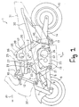
- FIG. 1 the reference numeral 1 denotes a motorcycle and the arrow Fr points to a forward driving direction.
- a body frame 2 of the motorcycle 1 has a main frame 3 in an inwards U-shape inside view.
- upper and lower links 4, 5 for vertical swinging are pivoted whereas on the swinging ends of these links a steering knuckle 7 for steering is supported and a front wheel 8 is rotatably supported at the lower end of the steering knuckle 7.
- a mid section of the lower link 5 is supported on a front portion of the main frame 3 through a front shock absorber 9 for absorbing shocks that the front reel 8 receives from the running surface.
- a bracket 10 projects upwardly and forwardly from the main frame 3 and handle bar 11 is supported on the projected end of this bracket 10.
- the handle bar 11 and the steering knuckle 7 are connected to each other through a connecting bar 12 and the front wheel 8 is steered by the steering operation of the handle bar 11 through the steering knuckle 7.
- a rear arm 14 for vertical swinging is pivoted on the lower rear portion of the main frame 3 rotatably supporting a rear wheel 15 on the swinging end of this rear arm 14.
- the mid section of the rear arm 14 is supported on the upper rear portion of the main frame 3 through a rear shock absorber 16 and a link mechanism 17 for absorbing shocks the rear wheel 15 received from the running surface.
- a four cylinder 19 is supported.
- the rigidity of the main frame 3 is increased by detachably connecting the front and rear lower ends of the main frame 3 with each other with a reinforcement frame 20.
- dismounting of the engine 19 from the main frame 3 is facilitated by detaching the reinforcing frame 20.
- the engine 19 comprises a crankcase 21, cylinders 22 projecting upwardly and forwardly from the crankcase 21 and a fuel injection valve 23 mounted on the top of each cylinder 22.
- a power transmission device 24 is connected to a rear portion of the crank case 21 in order to transmit the power of the engine to the rear wheel 15 for driving the motorcycle 1.
- an intake pipe 26 extends upwardly and an air cleaner 17 is connected to the upper ends of said intake pipes 26. Intake air is sucked into the cylinders 22 passing through the air cleaner 27 and the intake pipe 26 successively.
- a fuel tank 28 is positioned and is supported on the main frame 3.
- a cover body 29 is provided, open from the the top for covering the air cleaner 27 and fuel tank 28.
- a seat frame 30 projects rearwardly and upwardly from a rear portion of the main frame 3 and a seat 31 is supported on the seat frame 30. Moreover, a covering 32 made of plastic is provided for covering the vehicle body from the front and from the left and right sides.
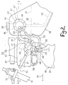
- the fuel tank 28 is made of sheet metal and has a fuel filler pipe 35 attached on its top surface and openly closed by a cap 36. In the lower portion of the fuel tank 28 fuel 37 is stored.
- the fuel 28 has a substantially circular opening 39 formed through its upper left side wall 38.
- the reference numeral 41 denotes a fuel pump device comprising a mounting plate 43 to be detachably mounted onto the side wall 38 of the fuel tank 28 from outside through bolts 42, and a fuel pump 44 supported by the mounting plate 43.
- the mounting plate 43 covers the opening 39 and the fuel pump 44 which is inserted into the interior of the fuel tank 28 through the opening 39.
- the ports for connecting the fuel pump 44 to the delivery and return passageways of the fuel supply and fuel return circuits are provided at the mounting plate 43.
- a suction 45 to the suction port of the fuel pump 44 is connected one end of a suction 45 while the other end of said suction hose 44 extends toward a bottom portion of the fuel tank 28 therein.
- a fuel filter is positioned on the left side of the air cleaner 27.
- a delivery pipe 48 which extends in a left-right transverse direction is installed near the top of the fuel injection valves 23 and each fuel injection valve 23 receives fuel from said delivery pipe 48.
- a pressure regulator valve 49 is installed on the lower side of the fuel filter 47.
- the delivery port of the fuel pump 44 is connected to the inlet of a fuel filter 47 through a first supply hose 50 and outlet of this fuel filter 47 is connected to the right end of the delivery pipe 48 through a second supply hose 51.
- the left-right section of the delivery pipe 48 is positioned in a surplus space between the air cleaner 27 and the bracket 10 in front of the air cleaner 27.
- the left end of the delivery pipe 48 is connected to the inlet of the pressure regulating valve 49 and the outlet of the pressure regulating 49 is connected to the return port of the fuel pump 44 through a return hose 53.
- Both hoses 51, 53 are made of synthetic resin and are flexible.
- Excessive fuel 37 left in the delivery pipe 48 is returned to the fuel pump 44 through the return hose 53 and is again supplied to the delivery pipe 48 together with other fuel sucked through the suction hose 45.
- the bolts 42 are loosened and the fuel pump 44 integrally provided with the mounting plate 43 is dismounted from the side wall 38 of the fuel tank 28.
- the opening 39 and the fuel pump device 41 (comprising the mounting plate 43 and the fuel pump 44) are disposed at an upper portion of the fuel tank 28, the fuel 37 starts in the lower portion of the fuel tank 28 kept therein even if the opening 39 is opened by dismounting the fuel pump device 41.
Landscapes
- Engineering & Computer Science (AREA)
- Mechanical Engineering (AREA)
- Cooling, Air Intake And Gas Exhaust, And Fuel Tank Arrangements In Propulsion Units (AREA)
- Automatic Cycles, And Cycles In General (AREA)
Applications Claiming Priority (2)
| Application Number | Priority Date | Filing Date | Title |
|---|---|---|---|
| JP289332/91 | 1991-10-07 | ||
| JP03289332A JP3075806B2 (ja) | 1991-10-07 | 1991-10-07 | 車両用燃料ポンプの配設構造 |
Publications (2)
| Publication Number | Publication Date |
|---|---|
| EP0536719A1 true EP0536719A1 (de) | 1993-04-14 |
| EP0536719B1 EP0536719B1 (de) | 1996-03-27 |
Family
ID=17741829
Family Applications (1)
| Application Number | Title | Priority Date | Filing Date |
|---|---|---|---|
| EP92117119A Expired - Lifetime EP0536719B1 (de) | 1991-10-07 | 1992-10-07 | Fahrzeug mit Motor |
Country Status (4)
| Country | Link |
|---|---|
| US (1) | US6626155B1 (de) |
| EP (1) | EP0536719B1 (de) |
| JP (1) | JP3075806B2 (de) |
| DE (1) | DE69209425T2 (de) |
Cited By (3)
| Publication number | Priority date | Publication date | Assignee | Title |
|---|---|---|---|---|
| EP0974513A3 (de) * | 1997-07-29 | 2000-07-19 | MV Agusta Motor S.p.A. | Mehrteiliger Tank für Motorrad |
| EP1862383A1 (de) * | 2006-05-31 | 2007-12-05 | Honda Motor Co., Ltd | Kraftstoffleitungsstruktur |
| EP2030883A1 (de) * | 2007-09-03 | 2009-03-04 | Yamaha Motor Research & Development Europe s.r.l. | Kraftstofftankanordnung für ein Motorrad und mit einer solchen Tankanordnung ausgestattetes Motorrad |
Families Citing this family (24)
| Publication number | Priority date | Publication date | Assignee | Title |
|---|---|---|---|---|
| JP3704993B2 (ja) * | 1999-02-22 | 2005-10-12 | スズキ株式会社 | 自動二輪車の燃料ポンプ装置 |
| AUPQ726900A0 (en) * | 2000-05-03 | 2000-05-25 | Orbital Engine Company (Australia) Proprietary Limited | In tank fuel pump |
| JP4077266B2 (ja) * | 2002-07-30 | 2008-04-16 | ヤマハ発動機株式会社 | 自動二輪車用エンジンの燃料供給装置 |
| JP4176449B2 (ja) * | 2002-10-30 | 2008-11-05 | 本田技研工業株式会社 | 小型車両における燃料配管構造 |
| JP4391756B2 (ja) * | 2003-03-20 | 2009-12-24 | 本田技研工業株式会社 | 自動二輪車の燃料ポンプ配置構造 |
| JP4128503B2 (ja) * | 2003-08-29 | 2008-07-30 | 本田技研工業株式会社 | 燃料タンク |
| US7992901B2 (en) * | 2004-01-27 | 2011-08-09 | Yamaha Hatsudoki Kabushiki Kaisha | Straddling type of vehicle |
| US7410022B1 (en) * | 2004-05-20 | 2008-08-12 | Polaris Industries Inc. | Fuel pickup return line and separator |
| JP4359542B2 (ja) * | 2004-08-23 | 2009-11-04 | ヤマハ発動機株式会社 | 車両 |
| ES2315807T3 (es) * | 2005-02-04 | 2009-04-01 | Honda Motor Co., Ltd. | Deposito de combustible. |
| JP2007137406A (ja) * | 2005-10-20 | 2007-06-07 | Yamaha Motor Co Ltd | 自動二輪車の燃料供給装置及び自動二輪車 |
| JP2007145132A (ja) * | 2005-11-25 | 2007-06-14 | Yamaha Motor Co Ltd | 自動二輪車 |
| JP4719560B2 (ja) * | 2005-12-01 | 2011-07-06 | 本田技研工業株式会社 | 自動二輪車 |
| ATE509684T1 (de) * | 2007-03-29 | 2011-06-15 | Honda Motor Co Ltd | Kraftstoffzufuhrvorrichtung und kraftstofffilterstruktur für fahrzeug |
| JP2008248751A (ja) * | 2007-03-29 | 2008-10-16 | Honda Motor Co Ltd | 燃料フィルタ構造 |
| US20080314670A1 (en) * | 2007-06-20 | 2008-12-25 | Buell Motorcycle Company | Fuel pump mounting for a motorcycle |
| JP4655075B2 (ja) * | 2007-07-30 | 2011-03-23 | スズキ株式会社 | スクータ型車両 |
| JP5002492B2 (ja) * | 2008-02-28 | 2012-08-15 | 本田技研工業株式会社 | 車両の燃料フィルタの取付構造 |
| JP5002491B2 (ja) * | 2008-02-28 | 2012-08-15 | 本田技研工業株式会社 | 車両の燃料供給装置 |
| JP5380229B2 (ja) * | 2009-09-29 | 2014-01-08 | 本田技研工業株式会社 | 自動二輪車の燃料供給装置 |
| JP5315192B2 (ja) * | 2009-09-29 | 2013-10-16 | 本田技研工業株式会社 | 自動二輪車の燃料供給装置 |
| JP5371669B2 (ja) * | 2009-09-30 | 2013-12-18 | 本田技研工業株式会社 | スクータ型車両 |
| JP5810017B2 (ja) * | 2012-03-22 | 2015-11-11 | 本田技研工業株式会社 | 鞍乗型車両の燃料供給構造 |
| JP6616728B2 (ja) * | 2016-04-06 | 2019-12-04 | 川崎重工業株式会社 | 乗物 |
Citations (3)
| Publication number | Priority date | Publication date | Assignee | Title |
|---|---|---|---|---|
| EP0203244A1 (de) * | 1985-05-25 | 1986-12-03 | FIAT AUTO S.p.A. | Befestigungssystem der Kraftstoffpumpe in einem Brennstoffbehälter |
| US4871041A (en) * | 1987-04-14 | 1989-10-03 | Honda Giken Kogyo Kabushiki Kaisha | Motorcycle fuel tank and fuel pump apparatus |
| JPH0228075A (ja) * | 1988-07-15 | 1990-01-30 | Yamaha Motor Co Ltd | 自動二輪車の燃料タンク装置 |
Family Cites Families (15)
| Publication number | Priority date | Publication date | Assignee | Title |
|---|---|---|---|---|
| US3802804A (en) * | 1967-07-21 | 1974-04-09 | March Mfg Co | Magnetically coupled pump structure |
| US3982856A (en) * | 1972-01-11 | 1976-09-28 | Karl Hehl | Base and power unit for injection molding machine |
| US3910464A (en) * | 1974-08-01 | 1975-10-07 | Gen Motors Corp | In-tank fuel pump support unit and assembly |
| JPS5186807A (de) * | 1975-01-28 | 1976-07-29 | Toyota Motor Co Ltd | |
| JPS5815756A (ja) * | 1981-07-21 | 1983-01-29 | Nippon Denso Co Ltd | 燃料タンクの配管取り出し構造 |
| JPS61104289A (ja) | 1984-10-26 | 1986-05-22 | 株式会社日立製作所 | 核融合炉の真空排気装置 |
| US4651701A (en) * | 1986-02-13 | 1987-03-24 | Steart-Warner Corp. | Submersible fuel pump and sender assembly |
| US4790185A (en) * | 1986-05-16 | 1988-12-13 | American Motors Corporation | Fuel sender mount |
| JPH0829175B2 (ja) | 1986-07-21 | 1996-03-27 | 株式会社三共 | 弾球遊技機 |
| JP2679037B2 (ja) | 1987-01-16 | 1997-11-19 | 株式会社デンソー | 半導体パッケージおよびその製造方法 |
| US4750513A (en) * | 1987-11-19 | 1988-06-14 | Chrysler Motors Corporation | Pivotally mounted fuel collector |
| GB8814726D0 (en) * | 1988-06-21 | 1988-07-27 | Glaxo Group Ltd | Medicaments |
| US5080077A (en) * | 1990-06-01 | 1992-01-14 | General Motors Corporation | Modular fuel delivery system |
| US5181839A (en) * | 1992-01-09 | 1993-01-26 | Walbro Corporation | Quick connect fuel pump assembly |
| US5218942A (en) * | 1992-11-30 | 1993-06-15 | General Motors Corporation | Modular fuel sender for motor vehicle |
-
1991
- 1991-10-07 JP JP03289332A patent/JP3075806B2/ja not_active Expired - Fee Related
-
1992
- 1992-10-07 EP EP92117119A patent/EP0536719B1/de not_active Expired - Lifetime
- 1992-10-07 DE DE69209425T patent/DE69209425T2/de not_active Expired - Fee Related
-
1995
- 1995-01-17 US US08/373,528 patent/US6626155B1/en not_active Expired - Fee Related
Patent Citations (3)
| Publication number | Priority date | Publication date | Assignee | Title |
|---|---|---|---|---|
| EP0203244A1 (de) * | 1985-05-25 | 1986-12-03 | FIAT AUTO S.p.A. | Befestigungssystem der Kraftstoffpumpe in einem Brennstoffbehälter |
| US4871041A (en) * | 1987-04-14 | 1989-10-03 | Honda Giken Kogyo Kabushiki Kaisha | Motorcycle fuel tank and fuel pump apparatus |
| JPH0228075A (ja) * | 1988-07-15 | 1990-01-30 | Yamaha Motor Co Ltd | 自動二輪車の燃料タンク装置 |
Cited By (3)
| Publication number | Priority date | Publication date | Assignee | Title |
|---|---|---|---|---|
| EP0974513A3 (de) * | 1997-07-29 | 2000-07-19 | MV Agusta Motor S.p.A. | Mehrteiliger Tank für Motorrad |
| EP1862383A1 (de) * | 2006-05-31 | 2007-12-05 | Honda Motor Co., Ltd | Kraftstoffleitungsstruktur |
| EP2030883A1 (de) * | 2007-09-03 | 2009-03-04 | Yamaha Motor Research & Development Europe s.r.l. | Kraftstofftankanordnung für ein Motorrad und mit einer solchen Tankanordnung ausgestattetes Motorrad |
Also Published As
| Publication number | Publication date |
|---|---|
| DE69209425T2 (de) | 1996-09-05 |
| US6626155B1 (en) | 2003-09-30 |
| JPH0599089A (ja) | 1993-04-20 |
| EP0536719B1 (de) | 1996-03-27 |
| JP3075806B2 (ja) | 2000-08-14 |
| DE69209425D1 (de) | 1996-05-02 |
Similar Documents
| Publication | Publication Date | Title |
|---|---|---|
| EP0536719A1 (de) | Fahrzeug mit Motor | |
| US8534406B2 (en) | Motorcycle | |
| JP5774129B2 (ja) | 鞍乗型車両 | |
| US20050081516A1 (en) | Exhaust control system for motorcycle | |
| US8371270B2 (en) | Fuel supply system for motorcycle | |
| CN104854319A (zh) | 骑乘型车辆 | |
| JP2015074353A (ja) | 鞍乗型車両 | |
| US7410191B2 (en) | Fuel tank mounting structure in saddle-ride type vehicle | |
| US9211930B2 (en) | Fuel supply system for motorcycle | |
| JP4244311B2 (ja) | 自動二輪車における燃料タンク構造 | |
| JP4128503B2 (ja) | 燃料タンク | |
| US20050274363A1 (en) | Fuel return structure of vehicle fuel pump | |
| CN110775182A (zh) | 鞍乘型车辆 | |
| US20030213627A1 (en) | Air intake system structure of scooter type vehicle | |
| EP2210801B1 (de) | Motorrad mit einer speziellen Anordnung von Benzintank, Benzinpumpe und Luftfilter | |
| US20050217631A1 (en) | Dry sump type lubrication device for a motorcycle | |
| JPH04372484A (ja) | スクーターの蒸発ガス回収装置 | |
| CN101767620B (zh) | 鞍乘型车辆 | |
| KR100715177B1 (ko) | 자동 이륜차의 연료 공급 장치 | |
| JP2014034345A (ja) | 鞍乗り型車両 | |
| JP3013429B2 (ja) | 自動二輪車のリアーフェンダ装置 | |
| EP1526024A2 (de) | Sekundärluftzuführvorrichtung und Motorrad mit dieser Vorrichtung | |
| MX2008003961A (es) | Sistema de suministro de combustible para vehiculos pequeños. | |
| JP6596756B2 (ja) | 鞍乗り型車両 | |
| JP2012052470A (ja) | 車両の燃料供給装置 |
Legal Events
| Date | Code | Title | Description |
|---|---|---|---|
| PUAI | Public reference made under article 153(3) epc to a published international application that has entered the european phase |
Free format text: ORIGINAL CODE: 0009012 |
|
| AK | Designated contracting states |
Kind code of ref document: A1 Designated state(s): DE FR IT |
|
| 17P | Request for examination filed |
Effective date: 19931013 |
|
| 17Q | First examination report despatched |
Effective date: 19940628 |
|
| GRAH | Despatch of communication of intention to grant a patent |
Free format text: ORIGINAL CODE: EPIDOS IGRA |
|
| GRAA | (expected) grant |
Free format text: ORIGINAL CODE: 0009210 |
|
| AK | Designated contracting states |
Kind code of ref document: B1 Designated state(s): DE FR IT |
|
| PG25 | Lapsed in a contracting state [announced via postgrant information from national office to epo] |
Ref country code: IT Free format text: LAPSE BECAUSE OF FAILURE TO SUBMIT A TRANSLATION OF THE DESCRIPTION OR TO PAY THE FEE WITHIN THE PRE;WARNING: LAPSES OF ITALIAN PATENTS WITH EFFECTIVE DATE BEFORE 2007 MAY HAVE OCCURRED AT ANY TIME BEFORE 2007. THE CORRECT EFFECTIVE DATE MAY BE DIFFERENT FROM THE ONE RECORDED.SCRIBED TIME-LIMIT Effective date: 19960327 |
|
| REF | Corresponds to: |
Ref document number: 69209425 Country of ref document: DE Date of ref document: 19960502 |
|
| ET | Fr: translation filed | ||
| PLBE | No opposition filed within time limit |
Free format text: ORIGINAL CODE: 0009261 |
|
| 26N | No opposition filed | ||
| PGFP | Annual fee paid to national office [announced via postgrant information from national office to epo] |
Ref country code: DE Payment date: 20081014 Year of fee payment: 17 |
|
| PGFP | Annual fee paid to national office [announced via postgrant information from national office to epo] |
Ref country code: FR Payment date: 20081014 Year of fee payment: 17 |
|
| REG | Reference to a national code |
Ref country code: FR Ref legal event code: ST Effective date: 20100630 |
|
| PG25 | Lapsed in a contracting state [announced via postgrant information from national office to epo] |
Ref country code: FR Free format text: LAPSE BECAUSE OF NON-PAYMENT OF DUE FEES Effective date: 20091102 Ref country code: DE Free format text: LAPSE BECAUSE OF NON-PAYMENT OF DUE FEES Effective date: 20100501 |