EP2030922A2 - Procédé et dispositif de transport d'un objet plat - Google Patents
Procédé et dispositif de transport d'un objet plat Download PDFInfo
- Publication number
- EP2030922A2 EP2030922A2 EP08105146A EP08105146A EP2030922A2 EP 2030922 A2 EP2030922 A2 EP 2030922A2 EP 08105146 A EP08105146 A EP 08105146A EP 08105146 A EP08105146 A EP 08105146A EP 2030922 A2 EP2030922 A2 EP 2030922A2
- Authority
- EP
- European Patent Office
- Prior art keywords
- gap
- thickness
- measured
- conveying
- conveyor
- Prior art date
- Legal status (The legal status is an assumption and is not a legal conclusion. Google has not performed a legal analysis and makes no representation as to the accuracy of the status listed.)
- Withdrawn
Links
- 238000000034 method Methods 0.000 title claims abstract description 24
- 230000004888 barrier function Effects 0.000 claims description 13
- 230000008859 change Effects 0.000 claims description 3
- 238000006073 displacement reaction Methods 0.000 claims description 2
- 230000001419 dependent effect Effects 0.000 claims 1
- 230000032258 transport Effects 0.000 description 52
- 239000003607 modifier Substances 0.000 description 3
- 230000008569 process Effects 0.000 description 3
- 230000009471 action Effects 0.000 description 2
- 238000012545 processing Methods 0.000 description 2
- 238000012549 training Methods 0.000 description 2
- 230000001960 triggered effect Effects 0.000 description 2
- 238000005452 bending Methods 0.000 description 1
- 208000027744 congestion Diseases 0.000 description 1
- 230000003247 decreasing effect Effects 0.000 description 1
- 238000002474 experimental method Methods 0.000 description 1
- 230000006870 function Effects 0.000 description 1
- 230000005484 gravity Effects 0.000 description 1
- 239000002184 metal Substances 0.000 description 1
- 230000004048 modification Effects 0.000 description 1
- 238000012986 modification Methods 0.000 description 1
- 230000009467 reduction Effects 0.000 description 1
- 238000010008 shearing Methods 0.000 description 1
Images


Classifications
-
- B—PERFORMING OPERATIONS; TRANSPORTING
- B65—CONVEYING; PACKING; STORING; HANDLING THIN OR FILAMENTARY MATERIAL
- B65H—HANDLING THIN OR FILAMENTARY MATERIAL, e.g. SHEETS, WEBS, CABLES
- B65H5/00—Feeding articles separated from piles; Feeding articles to machines
- B65H5/02—Feeding articles separated from piles; Feeding articles to machines by belts or chains, e.g. between belts or chains
- B65H5/021—Feeding articles separated from piles; Feeding articles to machines by belts or chains, e.g. between belts or chains by belts
- B65H5/025—Feeding articles separated from piles; Feeding articles to machines by belts or chains, e.g. between belts or chains by belts between belts and rotary means, e.g. rollers, drums, cylinders or balls, forming a transport nip
-
- B—PERFORMING OPERATIONS; TRANSPORTING
- B65—CONVEYING; PACKING; STORING; HANDLING THIN OR FILAMENTARY MATERIAL
- B65H—HANDLING THIN OR FILAMENTARY MATERIAL, e.g. SHEETS, WEBS, CABLES
- B65H2301/00—Handling processes for sheets or webs
- B65H2301/30—Orientation, displacement, position of the handled material
- B65H2301/32—Orientation of handled material
- B65H2301/321—Standing on edge
-
- B—PERFORMING OPERATIONS; TRANSPORTING
- B65—CONVEYING; PACKING; STORING; HANDLING THIN OR FILAMENTARY MATERIAL
- B65H—HANDLING THIN OR FILAMENTARY MATERIAL, e.g. SHEETS, WEBS, CABLES
- B65H2511/00—Dimensions; Position; Numbers; Identification; Occurrences
- B65H2511/10—Size; Dimensions
- B65H2511/13—Thickness
-
- B—PERFORMING OPERATIONS; TRANSPORTING
- B65—CONVEYING; PACKING; STORING; HANDLING THIN OR FILAMENTARY MATERIAL
- B65H—HANDLING THIN OR FILAMENTARY MATERIAL, e.g. SHEETS, WEBS, CABLES
- B65H2511/00—Dimensions; Position; Numbers; Identification; Occurrences
- B65H2511/20—Location in space
- B65H2511/22—Distance
- B65H2511/224—Nip between rollers, between belts or between rollers and belts
-
- B—PERFORMING OPERATIONS; TRANSPORTING
- B65—CONVEYING; PACKING; STORING; HANDLING THIN OR FILAMENTARY MATERIAL
- B65H—HANDLING THIN OR FILAMENTARY MATERIAL, e.g. SHEETS, WEBS, CABLES
- B65H2701/00—Handled material; Storage means
- B65H2701/10—Handled articles or webs
- B65H2701/19—Specific article or web
- B65H2701/1916—Envelopes and articles of mail
Definitions
- the invention relates to a method and a device for transporting a flat object, in particular a mail item, over a conveyor line.
- a sorting system sorts mailpieces depending on their respective destination address.
- the sorting system transports a stream of mail by means of conveyor belts.
- a conveyor line which comprises two endless conveyor belts. These conveyor belts are guided around a plurality of roles around. Some rollers are spring loaded. As a result, a thick mail item can increase the gap between the conveyor belts. The spring reduces the gap again when the transport of the mail item over the conveyor line has ended.
- a U-shaped transport channel for transporting flat, upright postal items.
- the side walls are formed by two endless conveyor belts 2, 3 and a narrow pressure belt 4.
- the distance between the two conveyor belts 2, 3 is significantly greater than the thickness of a transported mail item.
- the pressure belt 4 is located below the conveyor belt 3 and is pressed by two spring-mounted An fürumlenkrollen 13, 16 against the conveyor belt 2.
- An actuator moves the An fürumlenkrollen 13, 16 in dependence on the measured thickness perpendicular to the transport direction such that the gap between the bands 2 and 4 is changed.
- a thickness sensor measures the height of the transported stack.
- the gap between these conveyor belts 11, 22 is changed so that the gap is slightly less than the measured height, preferably only a few hundredths of a millimeter lower.
- WO 2004/030835 A1 An apparatus is described which measures the bending stiffness of a flat postal item.
- the mail item is temporarily clamped between three endless conveyor belts 1, 2a, 2b. In this case, a gap occurs between the two conveyor belts 2a, 2b.
- the thickness of the mail piece is measured.
- a roller 5 is displaced perpendicular to the transport direction, so that the distance between the roller and a connecting line between the two conveyor belts 2a, 2b is approximately equal to the measured thickness.
- the mailpiece is transported. The roller 5 is pressed in such a way against the clamped mail item. The deflection of the mail piece that causes the roll 5 is measured.
- the invention has for its object to provide a method for transporting a flat object over a conveyor line, in which the object is transported without the risk of congestion or slippage, the risk of damage to the transported object is reduced and useless gap changes are avoided ,
- the transport method and the transport device transport at least one flat article over a conveyor line.
- the transport device has two conveying elements, a thickness sensor and a gap changing device.
- the thickness of the object is measured before the object reaches the conveying path.
- the transport device transports the flat object vertically standing over the conveyor line.
- the two conveyor elements grasp the vertical object and temporarily clamp it between them.
- the two conveyor elements move at the same speed and transport the trapped object on the conveyor line.
- the conveyor elements grasp and clamp the article as it is being transported across the conveyor line. However, because the difference in thickness and gap is not greater than a predetermined barrier, damage to the article due to excessive lateral pressure is avoided. Because the two conveyor elements move at the same speed, buckling or shearing of the flat object is avoided.
- Some processing plants process flat objects vertically. For example, a feeder pulls one flat object one at a time from a stack of upright flat objects one at a time Processing plant can be more easily combined with a transport device, although the transport device transported the flat object upright and the object does not have to be rotated first.
- the device successively transports several objects over the conveyor line.
- the gap is set to a default value.
- This standard gap depends on a standard value for the thickness of the mailpieces to be transported.
- the gap is set to a different value only if the thickness of an article to be transported deviates from the standard thickness.
- the gap is returned to the standard gap after the article has been transported across the conveyor line, unless the subsequent article also has a thickness that deviates from the standard thickness.
- the current gap will only be changed if necessary.
- the gap is changed only if the thickness of the article to be transported deviates by more than a predetermined tolerance from the standard thickness.
- the transport device according to the invention is used in a sorting system that sorts flat postal items.
- the sorting system has a reading device which reads the respective destination address of each mail item.
- a system of driven endless conveyor belts transports the mail items through the sorting system and discharges them into one of several sorting compartments, depending on the respective destination address.
- each mail item should be clamped as much as necessary. Only then will it be ensured that the mail item is transported at the same speed with which the conveyor belts rotate, and thereby a given speed during the process Transportation is actually adhered to.
- the clamping is preferably effected in that the transported mail item deforms and / or deflects a conveyor belt of a conveyor track.
- the frictional force exerted by the conveyor belt depends on the restoring force that the deformed and / or deflected conveyor belt exerts on the mail item.
- the endless conveyor belts are in the embodiment on the outside with an elastic layer, preferably made Rubber, provided. This layer has a high coefficient of friction.
- the pulleys and the belt pulleys are made of metal.
- the belt pulleys have a smooth surface.
- each endless conveyor belt consists of two superposed individual endless conveyor belts.
- VS2 and VS4 pulleys and VS1 and VS3 belt pulleys can be moved vertically. This will be in Fig. 1 indicated by the four dashed double arrows.
- the transport device further has a gap changing device, which in Fig. 1 not shown.
- This gap changing device is able to move each adjustable conveying element VS1, VS2, VS3, VS4 independently of the other conveying elements by a predetermined distance perpendicular to the conveying direction F to the left or right.
- the gap changing device has actuators and a controller that determines the distance and the direction in which the conveying element is to be adjusted depending on the measured thickness and the previous position of a conveying element. The actuators make this adjustment.
- a value for the current gap can also be stored in each case a value that describes the current position of the adjustable conveyor element, for. B. the position on a coordinate axis perpendicular to the conveying direction.
- the actuators of the gap changing device performs the adjustment of the conveying elements.
- Such an actuator is z. B. off DE 10319723 B4 known.
- Two opposing endless conveyor belts each have a mail item which stands upright, to pinch between them and to transport it by rotation at the same speed in the conveying direction F.
- a mail piece is transported through the system by conveyor belts and belt pulleys, thereby describing a meandering path.
- the conveyor belts wrap around a transported mail item with a wrap angle of 3 degrees to 5 degrees.
- the speed of the mail item remains during transport through the arrangement of Fig. 1 constant and is known.
- the mail item initially passes the thickness sensor 10 on its path.
- the thickness sensor 10 measures the maximum thickness of the mail item, measured as an extent perpendicular to the conveying direction F.
- This light barrier 11 is arranged such that a predefined distance lies between the light barrier 11 and the beginning of the first conveying path FS1, which covers the mailpiece. Because the speed is known and constant, it is clear how long the mailing takes to cover the path to the first conveyor line FS1.
- the gap changing device adjusts the gap that occurs between the two opposing conveying elements VS1 and F3 to a predetermined value. This value depends on the thickness that the thickness sensor 10 has measured.
- the change in the gap starts at a time ⁇ T after the leading edge of the mail has passed the light barrier 11. Because the transport speed of the mail item is known, is in the embodiment determines that after the expiration of ⁇ T, the mail item is only a predetermined distance from the beginning of the first conveyor line FS1 and also only a predetermined distance away from the adjustable conveyor element VS1.
- the gap is adjusted so that the difference between the thickness of the mail piece and the gap is always in the same predetermined range. For example, the difference is always between 0 mm and 8 mm.
- the following gap is set as a function of the thickness of the mail item: Thickness of the mailing Gap between the conveyor elements ⁇ 8 mm The conveying elements are pressed against each other 8 mm - 10 mm The conveying elements touch each other without contact pressure 10 mm - 12 mm 2 mm > 12 mm 4 mm
- a default thickness for mailings z. B. 12 mm.
- the adjustable conveyor elements are initially adjusted so that a standard gap is created, for. B. one of 4 mm.
- This standard gap is set, for example, when the sorting system starts its operation.
- Fig. 1 the transport device is shown prior to transporting with the standard gaps.
- the gap modifier determines the old value of the gap, e.g. B. by reading the gap data memory and / or queries a position sensor for the adjustable conveyor element.
- the gap varying means calculates a new value for the gap and then from the old actual value and the new target value the distance and direction by which the adjustable conveying element is to be displaced.
- the gap is additionally adjusted depending on the respective weight of the item of mail.
- the transport of the mail item is effected solely by the fact that the conveying elements of the two conveyor lines clamp the mail item between them. Therefore, it is caused that the clamping conveyor elements exert a contact pressure and thus a frictional force on the clamped mail item, which compensates for the weight.
- the contact pressure depends on the restoring force that exerts the deflected conveying element on the mailpiece.
- the transport device additionally has a scale which measures the weight of each continuous mail item.
- a scale which measures the weight of each continuous mail item.
- Such a scale is often already installed in the sorting system, z. Because the weight is being measured to check the fare.
- a scale that measures postal items in the movement is z. B. off EP 881956 B1 and from EP 1400790 B1 known.
- the length of the mail item (the extent in the conveying direction F) and the height of the mail item (the extent perpendicular to the conveying direction F in the vertical direction) are measured.
- an average specific weight of a mail item is determined and stored in a data memory of the transport device. The volume is calculated from the thickness, length and height of each mail item. The weight is calculated from the volume and the average specific gravity.
- Each adjustable conveyor element is adjusted so that the larger the weight, the lower the gap. Heavy postal items are thereby subjected to a higher contact pressure than to light postal items.
- Fig. 2 shows the transport device of Fig. 1 in which a thick mail item Ps1 triggers the adjustment of a conveying element.
- the thick mail item Ps1 has reached the pulley 1.
- the process becomes triggered that the controlled actuator of the gap changing means the belt deflection roller VS1 shifts to the left, thereby increasing the gap between VS1 and F3.
- the shift is indicated by a dashed arrow. This adjusts the gap to the thickness of Ps1.
- the conveyor belts F2 and F3 transport the mail item Ps1 from the position in Fig. 2 to the position in Fig. 3 , During this transport, the belt pulley VS1 is adjusted by moving it to the left.
- Fig. 3 shows the transport device of Fig. 1 in the situation where the thick mailing of Fig. 2 the adjusted belt pulley VS1 reached.
- the gap between VS1 and F3 is adapted to the thickness of the mail piece Ps1.
- the belt deflection roller VS1 presses the mail item Ps1 to the conveyor belt F3, and the conveyor belt F3 further transports the mail item Ps1 in the conveying direction F.
- Fig. 4 shows the transport device of Fig. 1 in which the thick mail item Ps1 of Fig. 3 the adjustment of a further conveying element triggers, namely the driven pulley VS2.
- the pulley VS2 is displaced by being shifted to the right, which increases the gap between the conveyor belts F3 and F4.
- the adjustment of VS2 is started the moment that the mail item Ps1 in the Fig. 4 reached shown position. This is accomplished by starting the shift a predetermined amount of time after the leading edge of the mailpiece Ps1 has passed the photocell 22.
- a thin mail item Ps2 is transported after the thick mail item Ps1.
- an adjustment of the belt deflection roller VS1 is triggered. Because the subsequent mail item Ps2 is thinner than the leading mail item Ps1, the gap becomes decreased again between VS1 and F3. This is caused by a shift from VS1 to the right.
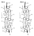
- Fig. 6 shows an alternative to Fig. 5 :
- the thick mail item Ps1 is followed by another thick mail item Ps3.
- the adjustable belt pulley VS1 remains in the previous position. The adjustment of the belt pulley is thus in the example of Fig. 6 suppressed.
- the stiffness of each postal item is additionally measured before it reaches the first conveyor line.
- a method to measure the stiffness of a mailpiece is over WO 2004/030835 A1 known.
- the postal item whose stiffness is to be measured is fixed in two places so that it can not be displaced in a direction perpendicular to the transport direction at these locations.
- a predetermined force is exerted on the mail item perpendicular to the transport direction. This force bends the mailpiece and the mailpiece exerts a restoring force on the acting element. It is measured how long the distance around which the mail item is bent at the point of action at which the force is exerted. The longer the distance, the lower the stiffness.
- the mail item is bent so far that the deflection at the point of action is equal to a predetermined path. It is measured how big then the restoring force that exerts the mailing. The greater the restoring force, the greater the rigidity.
- the mailing Ps5 of Fig. 7 and the mailing Ps6 of Fig. 8 are the same size. However, the mail item Ps5 of Fig. 7 low rigidity and is flexible. The mailing Ps6 of Fig. 8 has a high stiffness and is quite rigid.
- Fig. 7 the displacement already before the flexible mail item Ps5 has reached the Riemenumlenkrolle 22.
- the flexible mail item Ps5 can be adapted to the conveyor belt F10.
- Fig. 8 The shift begins only after the leading edge of the rigid mail item Ps6 has passed the belt deflection roller 22.
- the rigid mail item Ps6 can hardly adapt to the conveyor belt F10.
Landscapes
- Engineering & Computer Science (AREA)
- Mechanical Engineering (AREA)
- Sorting Of Articles (AREA)
- Delivering By Means Of Belts And Rollers (AREA)
Applications Claiming Priority (1)
| Application Number | Priority Date | Filing Date | Title |
|---|---|---|---|
| DE102007041006A DE102007041006A1 (de) | 2007-08-30 | 2007-08-30 | Verfahren und Vorrichtung zum Transport eines flachen Gegenstands |
Publications (2)
| Publication Number | Publication Date |
|---|---|
| EP2030922A2 true EP2030922A2 (fr) | 2009-03-04 |
| EP2030922A3 EP2030922A3 (fr) | 2012-12-05 |
Family
ID=40090249
Family Applications (1)
| Application Number | Title | Priority Date | Filing Date |
|---|---|---|---|
| EP08105146A Withdrawn EP2030922A3 (fr) | 2007-08-30 | 2008-08-27 | Procédé et dispositif de transport d'un objet plat |
Country Status (3)
| Country | Link |
|---|---|
| US (1) | US8020863B2 (fr) |
| EP (1) | EP2030922A3 (fr) |
| DE (1) | DE102007041006A1 (fr) |
Families Citing this family (6)
| Publication number | Priority date | Publication date | Assignee | Title |
|---|---|---|---|---|
| DE102009039066A1 (de) * | 2009-08-27 | 2011-03-10 | Siemens Aktiengesellschaft | Vorrichtung und Verfahren zum Vereinzeln von flachen Gegenständen mit Kompensation der Abnutzung |
| EP2594394A1 (fr) * | 2010-08-31 | 2013-05-22 | Heidelberger Druckmaschinen AG | Module d'inspection |
| JP2012062179A (ja) * | 2010-09-17 | 2012-03-29 | Toshiba Corp | 紙葉類処理装置 |
| DE102011004091A1 (de) * | 2011-02-14 | 2012-08-16 | Siemens Aktiengesellschaft | Verfahren und Vorrichtung zum Sortieren von flachen Gegenständen mit Lückenver derung |
| US9171430B2 (en) * | 2013-08-06 | 2015-10-27 | Ncr Corporation | Media item transporter |
| EP2843631B1 (fr) * | 2013-08-20 | 2019-05-22 | Kabushiki Kaisha Toshiba | Dispositif de discrimination de feuilles et appareil de traitement de feuilles |
Citations (10)
| Publication number | Priority date | Publication date | Assignee | Title |
|---|---|---|---|---|
| US3951257A (en) | 1974-10-30 | 1976-04-20 | Pitney-Bowes, Inc. | Mail transporting mechanism |
| US4973039A (en) | 1988-04-16 | 1990-11-27 | Bielomatik Leuze Gmbh & Co. | Device for retarding sheet stacks |
| DE19528828C1 (de) | 1995-08-05 | 1996-08-29 | Licentia Gmbh | Verfahren zur Steuerung einer Briefverteilanlage |
| DE19753419C1 (de) | 1997-12-02 | 1999-02-18 | Siemens Ag | Einrichtung zur Geschwindigkeitsänderung |
| EP0881956B1 (fr) | 1996-02-06 | 2000-04-05 | Siemens Aktiengesellschaft | Dispositif de determination automatique du poids d'envois postaux |
| EP1154944B1 (fr) | 1998-12-24 | 2004-03-17 | Solystic | Appareil permettant le transport d'objet plats entre les postes d'un equipement de traitement |
| WO2004030835A1 (fr) | 2002-09-27 | 2004-04-15 | Siemens Aktiengesellschaft | Dispositif pour mesurer la resistance au pliage d'envois plats |
| DE10319723B3 (de) | 2003-05-02 | 2004-09-16 | Siemens Ag | Verfahren und Vorrichtung zum Ausrichten von flachen Sendungen auf eine Schmalseite |
| DE102004022027B3 (de) | 2004-05-03 | 2005-12-08 | Siemens Ag | Vorrichtung zum Transport von flachen Sendungen in aufrechter Position |
| EP1400790B1 (fr) | 2002-09-20 | 2006-06-07 | Siemens Aktiengesellschaft | Procédé pour peser des articles de courrier |
Family Cites Families (15)
| Publication number | Priority date | Publication date | Assignee | Title |
|---|---|---|---|---|
| DE1116602B (de) | 1960-09-01 | 1961-11-02 | Telefunken Patent | Foerderstrecke zum Ausrichten von leichtem, flachem Sortiergut in einer Hochkant-Foerderbandanlage |
| DE3412574C1 (de) * | 1984-04-04 | 1985-10-10 | Baeuerle Gmbh Mathias | Bogenanleger fuer Papierverarbeitungsmaschinen mit einer auf unterschiedliche Bogendicken einstellbaren Vereinzelungsvorrichtung |
| DE3709659C2 (de) | 1987-03-24 | 1995-06-08 | Licentia Gmbh | Vorrichtung zum Ausrichten von Briefen und ähnlichem flachen Fördergut |
| JP3205624B2 (ja) * | 1992-12-28 | 2001-09-04 | キヤノン株式会社 | 給紙装置 |
| US5401013A (en) * | 1993-09-16 | 1995-03-28 | Bryce Office Systems, Inc. | Addressing machine feed gap setting |
| US5568917A (en) * | 1994-07-08 | 1996-10-29 | Am International, Inc. | Apparatus for calipering a collated assemblage |
| DE19528829C2 (de) | 1995-08-05 | 1998-04-30 | Siemens Ag | Vorrichtung zum Ausrichten von flachen Sendungen |
| JP4217340B2 (ja) * | 1999-04-15 | 2009-01-28 | キヤノン株式会社 | シート材検出装置及びシート材搬送装置及び画像形成装置 |
| US6619657B2 (en) * | 2000-03-14 | 2003-09-16 | Canon Kabushiki Kaisha | Curl correction device, and image forming apparatus having the curl correction device |
| DE10302406B4 (de) * | 2002-11-27 | 2004-09-30 | Wincor Nixdorf International Gmbh | Kartenhaltevorrichtung in einem Kartenbearbeitungsgerät |
| US20050161877A1 (en) * | 2004-01-26 | 2005-07-28 | Konica Minolta Medical & Graphic, Inc. | Image forming system |
| JP2005314089A (ja) * | 2004-04-30 | 2005-11-10 | Komori Corp | 搬送装置 |
| US7217232B2 (en) * | 2004-10-26 | 2007-05-15 | Sop Services, Inc. | Automatic paper folder |
| US7641193B2 (en) * | 2006-10-31 | 2010-01-05 | Hewlett-Packard Development Company, L.P. | Sheet bending |
| JP4922079B2 (ja) * | 2007-06-20 | 2012-04-25 | 株式会社東芝 | 紙葉類処理装置 |
-
2007
- 2007-08-30 DE DE102007041006A patent/DE102007041006A1/de not_active Withdrawn
-
2008
- 2008-08-27 EP EP08105146A patent/EP2030922A3/fr not_active Withdrawn
- 2008-09-02 US US12/202,934 patent/US8020863B2/en not_active Expired - Fee Related
Patent Citations (10)
| Publication number | Priority date | Publication date | Assignee | Title |
|---|---|---|---|---|
| US3951257A (en) | 1974-10-30 | 1976-04-20 | Pitney-Bowes, Inc. | Mail transporting mechanism |
| US4973039A (en) | 1988-04-16 | 1990-11-27 | Bielomatik Leuze Gmbh & Co. | Device for retarding sheet stacks |
| DE19528828C1 (de) | 1995-08-05 | 1996-08-29 | Licentia Gmbh | Verfahren zur Steuerung einer Briefverteilanlage |
| EP0881956B1 (fr) | 1996-02-06 | 2000-04-05 | Siemens Aktiengesellschaft | Dispositif de determination automatique du poids d'envois postaux |
| DE19753419C1 (de) | 1997-12-02 | 1999-02-18 | Siemens Ag | Einrichtung zur Geschwindigkeitsänderung |
| EP1154944B1 (fr) | 1998-12-24 | 2004-03-17 | Solystic | Appareil permettant le transport d'objet plats entre les postes d'un equipement de traitement |
| EP1400790B1 (fr) | 2002-09-20 | 2006-06-07 | Siemens Aktiengesellschaft | Procédé pour peser des articles de courrier |
| WO2004030835A1 (fr) | 2002-09-27 | 2004-04-15 | Siemens Aktiengesellschaft | Dispositif pour mesurer la resistance au pliage d'envois plats |
| DE10319723B3 (de) | 2003-05-02 | 2004-09-16 | Siemens Ag | Verfahren und Vorrichtung zum Ausrichten von flachen Sendungen auf eine Schmalseite |
| DE102004022027B3 (de) | 2004-05-03 | 2005-12-08 | Siemens Ag | Vorrichtung zum Transport von flachen Sendungen in aufrechter Position |
Also Published As
| Publication number | Publication date |
|---|---|
| US20090115127A1 (en) | 2009-05-07 |
| US8020863B2 (en) | 2011-09-20 |
| DE102007041006A1 (de) | 2009-03-05 |
| EP2030922A3 (fr) | 2012-12-05 |
Similar Documents
| Publication | Publication Date | Title |
|---|---|---|
| DE69808407T2 (de) | Papiersortiervorrichtung zum Sortieren von Papierblättern und Artikeln | |
| EP3248914B1 (fr) | Glissière pour marchandise de détail et procédé d'utilisation d'une telle glissière | |
| DE3217381C2 (de) | Vorrichtung zum Beschicken von Wanderrosten mit Grünpellets | |
| EP2030922A2 (fr) | Procédé et dispositif de transport d'un objet plat | |
| DE19821871A1 (de) | Vorrichtung und Verfahren zum Vereinzeln eines Stapels blattförmiger Aufzeichnungsträger | |
| EP1620210B1 (fr) | Procede et dispositif pour aligner des envois plats sur un cote etroit | |
| CH647476A5 (de) | Transportvorrichtung fuer blattgut. | |
| EP2304699B1 (fr) | Procede et dispositif de traitement de documents de valeur | |
| EP2310307A2 (fr) | Dispositif d'éjection d'un objet plat | |
| EP1080028B1 (fr) | Dispositif pour transporter une matiere en forme de feuille | |
| DE102009031117B3 (de) | Vorrichtung und Verfahren zur stapelförmigen Ablage von bogenförmigen Substraten | |
| EP4310032A1 (fr) | Dispositif d'alignement ou de positionnement. rotation d'objets avec une surface glissante | |
| EP4317030A1 (fr) | Dispositif de transport d'objets | |
| DE102010047562A1 (de) | Bandförderer mit längenveränderbarer Bandunterstützung | |
| DE102022116481A1 (de) | Vorrichtung zum Ausrichten von Objekten | |
| DE60318739T2 (de) | Verfahren und vorrichtung zur handhabung von walzen | |
| DE19960347C2 (de) | Vorrichtung zum Ablenken eines Schuppenstroms auf einem Rolltisch | |
| EP0522440A2 (fr) | Dispositif d'essai de l'étanchéité de gobelets fermés hermétiquement par une couvercle | |
| EP0017227A1 (fr) | Dispositif pour le démariage des feuilles composant une pile | |
| DE29520112U1 (de) | Vorrichtung zum Trennen und seitlichem Auslenken durch Längsschnitt erzeugten Metallstreifen | |
| DE29601452U1 (de) | Stapelvorrichtung für kartenförmige Güter | |
| EP1218271B1 (fr) | Dispositif pour tourner une pile de papier | |
| EP4175773A1 (fr) | Machine à dresser et procédé de redressage d'une bande métallique ou d'une pièce métallique plate | |
| EP1538115B1 (fr) | Méthode pour le transport de produits | |
| DD211293A1 (de) | Vorrichtung zum richten von blechstreifen |
Legal Events
| Date | Code | Title | Description |
|---|---|---|---|
| PUAI | Public reference made under article 153(3) epc to a published international application that has entered the european phase |
Free format text: ORIGINAL CODE: 0009012 |
|
| AK | Designated contracting states |
Kind code of ref document: A2 Designated state(s): AT BE BG CH CY CZ DE DK EE ES FI FR GB GR HR HU IE IS IT LI LT LU LV MC MT NL NO PL PT RO SE SI SK TR |
|
| AX | Request for extension of the european patent |
Extension state: AL BA MK RS |
|
| RIC1 | Information provided on ipc code assigned before grant |
Ipc: B65H 5/06 20060101AFI20120627BHEP Ipc: B65H 5/02 20060101ALI20120627BHEP |
|
| PUAL | Search report despatched |
Free format text: ORIGINAL CODE: 0009013 |
|
| RIC1 | Information provided on ipc code assigned before grant |
Ipc: B65H 5/02 20060101ALI20121012BHEP Ipc: B65H 5/06 20060101AFI20121012BHEP |
|
| AK | Designated contracting states |
Kind code of ref document: A3 Designated state(s): AT BE BG CH CY CZ DE DK EE ES FI FR GB GR HR HU IE IS IT LI LT LU LV MC MT NL NO PL PT RO SE SI SK TR |
|
| AX | Request for extension of the european patent |
Extension state: AL BA MK RS |
|
| RAP1 | Party data changed (applicant data changed or rights of an application transferred) |
Owner name: SIEMENS AKTIENGESELLSCHAFT |
|
| AKY | No designation fees paid | ||
| REG | Reference to a national code |
Ref country code: DE Ref legal event code: R108 Effective date: 20130814 |
|
| STAA | Information on the status of an ep patent application or granted ep patent |
Free format text: STATUS: THE APPLICATION IS DEEMED TO BE WITHDRAWN |
|
| 18D | Application deemed to be withdrawn |
Effective date: 20130606 |