EP3248914B1 - Glissière pour marchandise de détail et procédé d'utilisation d'une telle glissière - Google Patents
Glissière pour marchandise de détail et procédé d'utilisation d'une telle glissière Download PDFInfo
- Publication number
- EP3248914B1 EP3248914B1 EP17163845.5A EP17163845A EP3248914B1 EP 3248914 B1 EP3248914 B1 EP 3248914B1 EP 17163845 A EP17163845 A EP 17163845A EP 3248914 B1 EP3248914 B1 EP 3248914B1
- Authority
- EP
- European Patent Office
- Prior art keywords
- slide
- finger
- finger elements
- elements
- packaged goods
- Prior art date
- Legal status (The legal status is an assumption and is not a legal conclusion. Google has not performed a legal analysis and makes no representation as to the accuracy of the status listed.)
- Active
Links
Images


Classifications
-
- B—PERFORMING OPERATIONS; TRANSPORTING
- B65—CONVEYING; PACKING; STORING; HANDLING THIN OR FILAMENTARY MATERIAL
- B65G—TRANSPORT OR STORAGE DEVICES, e.g. CONVEYORS FOR LOADING OR TIPPING, SHOP CONVEYOR SYSTEMS OR PNEUMATIC TUBE CONVEYORS
- B65G11/00—Chutes
- B65G11/20—Auxiliary devices, e.g. for deflecting, controlling speed of, or agitating articles or solids
- B65G11/203—Auxiliary devices, e.g. for deflecting, controlling speed of, or agitating articles or solids for articles
-
- B—PERFORMING OPERATIONS; TRANSPORTING
- B65—CONVEYING; PACKING; STORING; HANDLING THIN OR FILAMENTARY MATERIAL
- B65G—TRANSPORT OR STORAGE DEVICES, e.g. CONVEYORS FOR LOADING OR TIPPING, SHOP CONVEYOR SYSTEMS OR PNEUMATIC TUBE CONVEYORS
- B65G11/00—Chutes
- B65G11/02—Chutes of straight form
-
- B—PERFORMING OPERATIONS; TRANSPORTING
- B65—CONVEYING; PACKING; STORING; HANDLING THIN OR FILAMENTARY MATERIAL
- B65G—TRANSPORT OR STORAGE DEVICES, e.g. CONVEYORS FOR LOADING OR TIPPING, SHOP CONVEYOR SYSTEMS OR PNEUMATIC TUBE CONVEYORS
- B65G11/00—Chutes
- B65G11/02—Chutes of straight form
- B65G11/023—Chutes of straight form for articles
-
- B—PERFORMING OPERATIONS; TRANSPORTING
- B65—CONVEYING; PACKING; STORING; HANDLING THIN OR FILAMENTARY MATERIAL
- B65G—TRANSPORT OR STORAGE DEVICES, e.g. CONVEYORS FOR LOADING OR TIPPING, SHOP CONVEYOR SYSTEMS OR PNEUMATIC TUBE CONVEYORS
- B65G47/00—Article or material-handling devices associated with conveyors; Methods employing such devices
- B65G47/52—Devices for transferring articles or materials between conveyors i.e. discharging or feeding devices
-
- B—PERFORMING OPERATIONS; TRANSPORTING
- B65—CONVEYING; PACKING; STORING; HANDLING THIN OR FILAMENTARY MATERIAL
- B65G—TRANSPORT OR STORAGE DEVICES, e.g. CONVEYORS FOR LOADING OR TIPPING, SHOP CONVEYOR SYSTEMS OR PNEUMATIC TUBE CONVEYORS
- B65G47/00—Article or material-handling devices associated with conveyors; Methods employing such devices
- B65G47/52—Devices for transferring articles or materials between conveyors i.e. discharging or feeding devices
- B65G47/68—Devices for transferring articles or materials between conveyors i.e. discharging or feeding devices adapted to receive articles arriving in one layer from one conveyor lane and to transfer them in individual layers to more than one conveyor lane or to one broader conveyor lane, or vice versa, e.g. combining the flows of articles conveyed by more than one conveyor
- B65G47/71—Devices for transferring articles or materials between conveyors i.e. discharging or feeding devices adapted to receive articles arriving in one layer from one conveyor lane and to transfer them in individual layers to more than one conveyor lane or to one broader conveyor lane, or vice versa, e.g. combining the flows of articles conveyed by more than one conveyor the articles being discharged or distributed to several distinct separate conveyors or to a broader conveyor lane
-
- B—PERFORMING OPERATIONS; TRANSPORTING
- B65—CONVEYING; PACKING; STORING; HANDLING THIN OR FILAMENTARY MATERIAL
- B65G—TRANSPORT OR STORAGE DEVICES, e.g. CONVEYORS FOR LOADING OR TIPPING, SHOP CONVEYOR SYSTEMS OR PNEUMATIC TUBE CONVEYORS
- B65G11/00—Chutes
-
- B—PERFORMING OPERATIONS; TRANSPORTING
- B65—CONVEYING; PACKING; STORING; HANDLING THIN OR FILAMENTARY MATERIAL
- B65G—TRANSPORT OR STORAGE DEVICES, e.g. CONVEYORS FOR LOADING OR TIPPING, SHOP CONVEYOR SYSTEMS OR PNEUMATIC TUBE CONVEYORS
- B65G11/00—Chutes
- B65G11/20—Auxiliary devices, e.g. for deflecting, controlling speed of, or agitating articles or solids
-
- B—PERFORMING OPERATIONS; TRANSPORTING
- B65—CONVEYING; PACKING; STORING; HANDLING THIN OR FILAMENTARY MATERIAL
- B65G—TRANSPORT OR STORAGE DEVICES, e.g. CONVEYORS FOR LOADING OR TIPPING, SHOP CONVEYOR SYSTEMS OR PNEUMATIC TUBE CONVEYORS
- B65G11/00—Chutes
- B65G11/20—Auxiliary devices, e.g. for deflecting, controlling speed of, or agitating articles or solids
- B65G11/206—Auxiliary devices, e.g. for deflecting, controlling speed of, or agitating articles or solids for bulk
-
- B—PERFORMING OPERATIONS; TRANSPORTING
- B65—CONVEYING; PACKING; STORING; HANDLING THIN OR FILAMENTARY MATERIAL
- B65G—TRANSPORT OR STORAGE DEVICES, e.g. CONVEYORS FOR LOADING OR TIPPING, SHOP CONVEYOR SYSTEMS OR PNEUMATIC TUBE CONVEYORS
- B65G19/00—Conveyors comprising an impeller or a series of impellers carried by an endless traction element and arranged to move articles or materials over a supporting surface or underlying material, e.g. endless scraper conveyors
- B65G19/18—Details
- B65G19/28—Troughs, channels, or conduits
-
- B—PERFORMING OPERATIONS; TRANSPORTING
- B65—CONVEYING; PACKING; STORING; HANDLING THIN OR FILAMENTARY MATERIAL
- B65G—TRANSPORT OR STORAGE DEVICES, e.g. CONVEYORS FOR LOADING OR TIPPING, SHOP CONVEYOR SYSTEMS OR PNEUMATIC TUBE CONVEYORS
- B65G47/00—Article or material-handling devices associated with conveyors; Methods employing such devices
- B65G47/34—Devices for discharging articles or materials from conveyor
- B65G47/44—Arrangements or applications of hoppers or chutes
Definitions
- the invention relates to a slide for piece goods, with a slide floor for sliding the piece goods down comprising at least two slide floor sections, the at least two slide floor sections forming a height offset between one another, with at least one guide device between the at least two slide floor sections for guiding the piece goods from one slide floor section to the next slide floor section is provided and wherein the at least one guide device has a height-adjustable free end pointing in the direction of the next slide floor section.
- the invention further relates to a method for conveying piece goods along a slide of the type mentioned.
- Slides for general cargo of the type mentioned are used in particular for sorting packages and are designed as so-called box slides.
- the piece goods are sorted into a plurality of chutes in a sorting device, a so-called sorter, according to defined criteria.
- the piece goods slide down the slide bottom to the end of the slide, where the piece goods are temporarily stored in a collecting area until the piece goods are removed from the slide.
- the sorter generally has an elevated transport device, for example in the form of a belt conveyor or a roller conveyor, along which the piece goods are transported until they are diverted by the transport device into a slide, usually designed as a box slide. Over the slide the Height difference to the sorter overcome and the piece goods are transported to the side, where they can be easily removed. In addition, a larger area can be provided via the chute for the intermediate storage of the piece goods than if the piece goods were buffered directly at the transport device.
- an elevated transport device for example in the form of a belt conveyor or a roller conveyor, along which the piece goods are transported until they are diverted by the transport device into a slide, usually designed as a box slide. Over the slide the Height difference to the sorter overcome and the piece goods are transported to the side, where they can be easily removed.
- a larger area can be provided via the chute for the intermediate storage of the piece goods than if the piece goods were buffered directly at the transport device.
- the piece goods diverted into the slides often follow an identical or at least very similar path along the bottom of the slide, which usually represents a curved path (trajectory).
- the stored piece goods are therefore lined up in succession along the corresponding path.
- the slides are often cascaded. This means that at least two slide floor sections with a height difference between the two mutually facing ends of the slide floor sections are provided, which represents a jump for the piece goods.
- the slide floor sections therefore do not merge into one another and are also not arranged in alignment with one another. The jump ensures that the piece goods are randomly stacked on top of one another and / or if necessary experience a random change of direction.
- guide devices are provided in some slides between individual slide floor sections, which extend across the width of the slide floor and can be swiveled up and down about a horizontal axis.
- a sufficient transport speed of the piece goods is ensured by the guiding device being in the longitudinal direction of the Chute bottom driven belt conveyor is formed. If the packages are to be stacked, the guide device is pivoted upward with the free end pointing in the conveying direction in order to raise the general cargo to a higher level, so that the general cargo comes to rest on already stored general cargo. In this way, a cascade can ultimately be simulated and damage to the piece goods can be avoided.
- the slide described above and the method also described above are particularly suitable for sorting piece goods of different types.
- the piece goods can be products or goods, for example.
- packages which are packaged items, such as goods, shipments or other goods. This can also be bulk goods.
- Shipments are typically delivered to certain addressees. In addition, shipments are often packages, i.e. packaged piece goods.
- a sorting is often carried out in a delivery base, for example according to the geographical area of the addressees.
- the delivery base can be, for example, a so-called parcel center, a warehouse or the like.
- the shipments can be delivered after sorting or sorted further, which can be done at a different location, for example, than the previous sorting.
- the delivery can be effected to the addressees of the consignments or at corresponding delivery points, such as parcel boxes or packing stations.
- a slide of the type mentioned is for example from the DE 36 12 076 A1 known, which discloses a slide according to the preamble of claim 1.
- another slide, which does not correspond to the aforementioned type but is nevertheless similar, is from the JP 2001 315928 A known.
- the present invention is based on the object of designing and developing the slide and the method of the type mentioned at the outset and explained in more detail above in such a way that the overall effectiveness of the sorting can be increased.
- the finger elements carry a flexible material web bridging the spaces between the finger elements and / or in that the finger elements have at least one material web that rotates around at least one finger element and is driven in the longitudinal direction of the finger elements exhibit.
- the invention has recognized that the piece goods can be guided much more precisely along the slide floor if the guide device is provided with a plurality of finger elements which are arranged next to one another transversely to the slide floor and which are height-adjustable relative to one another.
- the free ends of adjacent finger elements, which form the free end of the guide device or can be assigned to it, can therefore be arranged at a different height.
- the guiding device can thus be designed in a targeted manner by adjusting the fingers against one another and against the slide floor in such a way that the piece goods are guided in the desired manner from one slide floor section to the subsequent slide floor section. This can mean, for example, that the piece goods to be stored are moved to different degrees across the slide floor.
- a movement component can be impressed on the piece goods transversely to the slide floor if the piece goods move over a surface that is inclined transversely to the slide floor, which in turn can be achieved by finger elements raised to different degrees in this area of the guide device. If all finger elements are lifted to the same extent so that the guide device is lifted uniformly everywhere, the guide device does not tilt transversely to the slide floor, but about a horizontal axis.
- the finger elements can also be adjusted so that the piece goods get to other packages and come to rest there. In this way, piece goods can be stored in different layers one above the other or as a randomly arranged pile, which is very space-saving.
- the finger elements can be adjusted just as far as is necessary for stacking piece goods on piece goods that already exist. This can mean, for example, that piece goods are lifted further by the finger elements, the higher the piece goods on which the piece goods to be added are to be stacked. Ultimately, this allows space-saving stacking of the piece goods with very little damage to the piece goods.
- the guide device can also be used to reduce the drop height of the packages from one slide floor section to the next slide floor section. This can be the case if the slide floor sections are arranged in a cascade. If, for example, no piece goods are provided at the lower end of a step of the cascade, the guide device can be brought into a position which allows a gentle transition of the piece goods from one slide floor section to the next slide floor section. Since the finger elements can be adjusted in height independently of one another, the fingers can be arranged at a different location at the same time at a different height, for example in order to direct another piece of goods there to a piece of goods already positioned before the cascade stage.
- the multiple, independently height-adjustable fingers provide considerable flexibility with which the guide device can act on the movement of the piece goods to be stored, in order to make sorting more effective overall.
- the finger elements in different sections of the guide device can be raised to different degrees in order to guide the piece goods in the different sections in different directions.
- the finger elements do not have to be completely independently adjustable.
- the finger elements are not positively coupled with regard to their height adjustability, in the sense that a finger element must always have the same relative position to another, in particular to an adjacent finger element, or in the sense that the position of a finger is caused by the position of another finger , in particular an adjacent finger, is precisely specified.
- the finger elements can be adjusted in height in a coordinated manner. For example, instead of a more chaotic course of the finger elements transverse to the guide device, a smooth course can be achieved, which will be preferred in principle, and the more so, the more finger elements are provided.
- the thinner the finger elements the more expedient it will be. This applies in particular to small piece goods.
- finger elements the size of human fingers can be preferred.
- the finger elements are arranged or distributed over the entire width of the slide, the width and / or the length of the respective slide being adapted to the size of the piece goods to be sorted or other parameters.
- the free ends of the finger elements are arranged at different heights. It is possible to react to different circumstances at different points of the guide device, so that the piece goods at the different points can be forwarded by the guide device to the next slide floor section as cheaply as possible and / or to provide a surface that is inclined transversely to the slide floor, so that one can pass over this surface To be able to impress a movement component across the slide floor.
- the guide device is arranged in a wave shape transversely to the slide floor due to the free ends of the finger elements positioned at different heights.
- the free ends of the finger elements can be arranged crosswise to the slide floor in sections in a lower position in sections in an upper position and / or in sections in a position between the lower position and the upper positions.
- the latter applies in particular, but not exclusively, in the event that a section with finger elements extends to one side of the corresponding section upper position and to the opposite side a section with finger elements in the lower position.
- a waveform can be provided.
- each section can also be aligned differently in order to take account of the conditions there with regard to a suitable management of the piece goods.
- the free ends of at least certain finger elements in the event that they are in a lower position at least approximately at the level of the next slide floor section are arranged.
- the height of the next slide floor section is understood in particular as the height of the beginning of the next slide floor section and / or the height of the next slide floor section in the region of the free ends of the correspondingly arranged finger elements. In the manner mentioned, a smooth transition of the inclination of the slide floor from one slide floor section to the next slide floor section can be provided.
- upper positions of the free ends of at least certain finger elements can be provided, which are arranged at least at a certain distance above the next slide floor section.
- the determined distance can depend on the design of the slide and / or the size of the piece goods.
- the height of the next slide floor section is understood in particular as the height of the start of the next slide floor section and / or the height of the next slide floor section in the area of one of the free ends of the verticals attacking the corresponding finger elements.
- stacking of the piece goods sliding down the chute can be achieved, in particular when piece goods are stacked on other piece goods.
- the height of the piece goods should then not exceed a certain value in order to enable the piece goods to be stacked in a given slide. Which height should not be exceeded depends on the design of the slide.
- the finger elements each have at least two flexible flank elements which together extend in the longitudinal direction of the finger element to the free end of the finger element, the flexible flank elements preferably being flexible with one another in the longitudinal direction of the finger elements, in each case via a plurality of webs are connected.
- the free ends of the finger elements can be easily adjusted from a lower position to an upper position and back.
- the finger elements can also use the so-called fin ray effect, which was observed in the tail fins of bone fish. If you press it with your finger on the side, the fins do not bend due to the Fin Ray effect, but bend towards the finger. This is made possible by the special structure of the fins, which is reproduced by the finger elements in the configuration described above.
- the finger elements have at least two flexible flank elements that extend jointly from one end of the finger element to an opposite end of the finger element.
- the flexibility of the flank elements can be provided, for example, by elastic flank elements or by a link chain made of rigid chain links pivotally or articulatedly connected to one another. Appropriate flexibility is only required in one spatial direction. Flexibility is not absolutely necessary in the spatial directions perpendicular to it. Therefore, the flank elements can also be designed without problems, for example in the form of strips, with the plane of the Stripe can result in increased bending stiffness. Alternatively, a rod-shaped configuration of the flank elements is also possible. The corresponding flexibility of the flank elements ultimately allows a curvature of the finger unit starting from an extended position into a curved position, for example similar to the curvature of a finger, in particular upwards or downwards.
- the at least two flank elements between the two ends of the finger elements are each flexibly connected to one another via a plurality of webs.
- the webs can be rigid and can be pivotally or articulatedly connected to the flank elements.
- flexible, in particular elastic, webs can also be used. In this way it is achieved that the webs can be pivoted in relation to the at least two flank elements in order to allow the finger element to be curved.
- the structure of the finger elements may allow the same to be curved, for example when a piece of goods presses on a finger element.
- the finger elements can in particular be curved in a targeted manner, which leads to a raising or lowering of the free end of the finger elements, without the need for contact with a piece goods, for example.
- the curvature or adjustment of the finger elements, with the focus in particular on raising and lowering the free ends of the finger elements, is carried out, for example, by adjusting the flank elements relative to one another in the longitudinal direction of the corresponding finger elements.
- the shape of the finger elements then results inevitably, in particular depending on the connection of the flank elements to one another via the webs in between.
- the flank elements can be mirror-symmetrical in a position of a finger element and / or the webs can be aligned parallel to one another.
- the finger elements can also have three or more flank elements which are connected to one another via webs.
- adjustability of the finger elements in one direction namely in particular the vertical direction, will generally be sufficient.
- the webs and the associated flexible flank elements In order to be able to ensure a suitable mobility and thus the adjustability of the finger elements, it is advisable for the webs and the associated flexible flank elements to have an acute angle of preferably between 10 ° and 80 ° on one side and an obtuse angle of preferably on the other side form between 100 ° and 170 °. Right angles, on the other hand, can hinder or restrict the adjustability of the finger elements.
- the flexible flank elements of the finger elements can be adjustable relative to one another in the longitudinal direction of the finger elements.
- the flank elements of different finger elements can be adjusted differently.
- the flank elements are preferably adjusted using a corresponding drive device which can be controlled in the desired manner in order to ensure the desired position of the finger elements. If necessary, the separate adjustment of the finger elements can be easily achieved by at least partially assigning separate drive devices to the different finger elements.
- the finger elements in an alternative according to the invention are covered with a flexible material web which also covers the spaces between the finger elements.
- Small or pointed piece goods cannot accidentally get into the spaces between the finger elements.
- the material web can are basically made of different materials.
- the piece goods can slide easily on smooth materials and can be braked on rough materials if necessary. The sliding friction can be adjusted if necessary by selecting the appropriate material pairings.
- the flexibility of the material web cannot only be ensured by the material used and its thickness.
- Flexible connections between sections of the material web can also be provided, which can be designed, for example, as hinges. If finger elements or their free ends are arranged next to one another at different heights at right angles to the slide floor, it can be achieved that the material web at least essentially follows this height difference.
- a circumferential, if necessary driven, material web is provided around at least one finger element.
- the material web can then be designed like a belt of a belt conveyor and, if necessary, can also be held along the at least one associated finger element.
- the material web is driven, namely in the longitudinal direction of the finger elements, for example so that the material web is moved on the finger elements in the direction of the free ends, the piece goods can be accelerated or braked as they pass the material web.
- the static friction and the sliding friction of the respective material pairings of general cargo and material web also play a role.
- At least one, preferably optical, sensor can be provided for detecting the respective operating situation.
- the operating situation is characterized, for example, by the number and / or type of individual stored piece goods, by the location of individual stored piece goods, by the dimensions of individual stored piece goods, by the arrangement of a heap of stored piece goods and / or by the shape of a heap of stored piece goods.
- This or these parameters are therefore preferably recorded and can be used to control or adjust the finger elements of a guide device. If, for example, the number of stored piece goods is recorded, it can be concluded how the piece goods already stored are arranged at the end of the slide.
- This information can be used to guide the subsequent piece goods in a certain direction by adjusting the guide device, for example to better utilize the space available for storing the piece goods or to avoid damage when the piece goods are conveyed.
- the type for example the shape or the size, of the piece goods
- the arrangement of the piece goods stored at the end of the slide can generally be inferred even better. It goes without saying that, for example, it can also be taken into account if all or only a few piece goods are removed from the slide.
- the removal of piece goods from the chute can also be detected by a sensor, in particular an optical sensor.
- the corresponding information can also be provided in another way, in particular for further processing thereof. If necessary, it may also be sufficient to only record the type of general cargo.
- the elapsed time or information provided in some other way about the number of piece goods can then be used to infer the arrangement of the stored piece goods in the slide.
- the position of individual stored piece goods and / or the dimensions of individual stored piece goods can also be detected by the sensor.
- the piece goods arranged in front of the corresponding guide device are of particular interest.
- the sensor can also detect a heap of piece goods, in particular the arrangement of a heap of stored piece goods and / or the shape of a heap of stored piece goods. Even then it can be expediently decided where further piece goods are going should be directed to then adjust the finger elements of the guide.
- the adjusting device can time-dependent the finger elements, depending on the number and / or type of individual stored packages and / or adjust or adjust depending on at least one parameter detected by the sensor. For the sake of simplicity, it is preferred for this purpose if the actuating device adjusts the finger elements on the basis of at least one signal which is transmitted from the sensor to the actuating device for detecting the corresponding parameters.
- finger elements can be carried by a hand element, which in turn is preferably designed to be height-adjustable.
- the finger elements provided in a guide device can be assigned to different hand elements. If the at least one hand element is adjustable relative to the slide floor, the finger elements held on the hand element can be adjusted, in particular raised, lowered or pivoted, together via the hand element.
- the finger elements, in particular the free ends of the finger elements, of a trading element can be adjusted relative to one another, for example raised and / or curved. In the manner described, for example, the adjustment range of the finger elements is increased in order to be able to use the finger elements particularly effectively and in a targeted manner.
- the at least one hand element, on which a plurality of finger elements is fixed is fixed on an arm element, which in turn can be arranged to be height-adjustable.
- the height adjustability can manifest itself, for example, in the fact that the arm element can be moved up and down and / or pivoted against the slide floor.
- a collecting area for piece goods can be provided at the lower end of the slide.
- the general cargo can then collect in the collecting area. If necessary, piece goods can only be routed via the guide device when the catchment area has at least partially filled and, for example, the piece goods reach back into the vicinity of the guide device.
- the height of the free ends of at least individual finger elements can be set according to different criteria. However, this is preferably done according to more or less precisely specified parameters.
- the finger elements can be adjusted, for example, in a time-dependent manner. The more time passes, the more piece goods are temporarily stored at the end of the slide, at least as long as the piece goods are not partially or completely removed from the slide. Additionally or alternatively, the finger elements can also be adjusted depending on the number and / or the type of individual piece goods stored. The number and type of piece goods, in particular the size and shape of the piece goods, allow conclusions to be drawn about the arrangement of the stored piece goods in the slide.
- the position and / or the dimensions of individual stored piece goods can be recorded, in particular the dimensions which are of particular interest for the management of further piece goods.
- the piece goods can be used in the transport direction behind the at least one guide device to adjust the finger elements.
- the arrangement and / or the shape of a heap of piece goods can also be used as a criterion which determines the adjustment of the finger elements. The latter allows particularly precise conclusions to be drawn as to how the piece goods still to be stored can be at least one guide device should be directed to influence the storage of the piece goods in the desired manner.
- the use of at least one sensor which determines the at least one parameter, is appropriate.
- the use of at least one optical sensor is particularly expedient for the detection and evaluation of the at least one parameter.
- the sensor can optionally detect the number and / or the type of individual stored piece goods, the location of individual stored piece goods, the dimensions of individual stored piece goods, the arrangement of a pile of stored piece goods and / or the shape of a pile of stored piece goods.
- the method can be implemented in a simple manner if the at least one sensor outputs a signal correlating with the at least one parameter to be determined, which signal can be passed on to an adjusting device for adjusting the height of the free ends of the finger elements depending on the signal.
- a sorting device 1 for sorting piece goods 2, in particular in the form of packages.
- the packages are in particular parcel shipments, i.e. primarily parcels and small packages for shipping to addressees.
- the sorting device 1 is part of a delivery base in which parcel deliveries are delivered, sorted and grouped on after sorting in order to ultimately effect the delivery of the piece goods 2 to the addressee.
- it can also be a warehouse, in which piece goods 2 are sorted in the form of goods in order to be transported together to another location.
- the sorting device 1 can, however, also be connected downstream of at least one production system in order to sort the produced products for subsequent use thereof.
- the piece goods 2 to be sorted are transported in via a transport device 3, which in the illustrated and in this respect preferred case is a belt conveyor.
- the transport device 3 extends along a plurality of chutes 4, each chute 4 being provided for specific piece goods 2 or classes of piece goods 2.
- a device which is not shown but is sufficiently known per se, is used to determine which general cargo 2 or what type of general cargo 2 it is in each case in order to decide in which slide 4 the respective general cargo 2 is to be directed.
- the general cargo 2 is at the corresponding level Slide 4, the piece goods 2 are guided into the slide 4 by a sorting device 1.
- pivotable flaps 5 are provided for feeding the piece goods 2 to a slide 4, which flaps 5 can be pivoted into a position obliquely to the direction of transport of the piece goods 2 via the transport device 3 and thereby push or guide the piece goods 2 into the corresponding slide 4 ,
- the slides 4 have an inclined slide floor 6, which provides the slide surface 7 on which the piece goods 2 slide down along the slide 4.
- the slide floor 6 is formed from a metallic material in the illustrated slide 4, which is preferred in this respect. Furthermore, it is preferably a so-called box slide, in which a side cheek 8 is provided on each side of the slide base 6 on both sides of the slide base 6, which prevents accidental lateral falling of piece goods 2 from the slide 4.
- two guide devices 9, 10 are provided at different heights of the slide 4.
- the guide devices 9, 10 extend transversely to the slide floor 6 or transversely to the transport direction of the piece goods 2 along the slide 4.
- the extension of the guide device 9, 10 can also be viewed as horizontal.
- the path that the piece goods 2 take along the slide floor 6 would be determined by the piece goods 2 and the movement components with which the piece goods 2 reach the slide 4.
- the guiding devices 9, 10 can influence the direction of transport of the piece goods 2 along the slide 4 by the guiding devices 9, 10 imprinting the piece goods 2 with a certain movement component, which can differ from piece goods 2 to piece goods 2, if necessary.
- the guide devices 9, 10 are provided between two slide floor sections 11, 12, 13. While the movement of the piece goods 2 along the slide bottom sections 11, 12, 13 cannot be influenced, the piece goods 2 can pass in a certain direction when passing the guide device 9, 10 be directed. This can be achieved by raising or lowering the guide device 9, 10 or at least parts thereof.
- the guide device 9, 10 has a free lower end 14 which is adjustable in height.
- the upper end 15 of the guide device 9, 10 ends at least approximately at the height of the slide floor section 11, 12 arranged above it, so that the piece goods 2 easily pass from a slide floor section 11, 12 to a guide device 9, 10 following the slide floor section 11, 12 can.
- the free lower end 14 of the guide device 9, 10 can be arranged at least approximately at the level of the adjoining slide bottom section 12, 13. The piece goods 2 can then move continuously or uniformly, in particular without a jump, from the guide device 9, 10 to the subsequent slide floor section 12, 13.
- the guide devices 9, 10 can then brake the piece goods 2 as required, which can lead to the piece goods 2 sliding in another direction as a result of the guide device 9, 10 on the subsequent slide floor section 12, 13.
- braking the piece goods 2 can already lead to the piece goods 2 being guided.
- a movement component is impressed on the piece goods 2 in particular by a targeted height adjustment of the guide device 9, 10.
- the guide device 9, 10 can be raised or lowered overall.
- the guide device 9, 10, however, has, as shown in detail in the guide device Fig. 2 is shown, a series of finger elements 16, which are arranged along the extension of the guide device 9, 10 transversely to the slide floor 6, in particular uniformly, and are adjustable in height independently of one another.
- the finger elements 16 are arranged under a flexible material web 17 which at least partially rests on the finger elements 16 or is at least partially carried by the finger elements 16.
- the material web 17 is also so flexible that it can adapt to the position of the finger elements 16 transverse to the slide 4.
- the finger elements 16 can thus shape the contour of the guide device 9, 10 transversely to the slide 4 specify that the material web 17 at least substantially follows. If the curvature of the finger elements 16 changes during the height adjustment of the free ends 18 of the finger elements 16, this preferably also has an effect on the arrangement of the material web 17, which preferably also at least essentially follows the curvature of the finger elements 16 along their longitudinal extent. In addition, the free ends 18 of the finger elements 16 are assigned to the lower end 14 of the material web 17 and the guide device 9, 10. Otherwise, material webs 17 made of plastic, in particular plastic films, are available, which are preferably relatively abrasion-resistant.
- the finger elements 16 of the guide devices 9, 10 are each provided at least substantially independently of the other finger elements 16 in a height-adjustable manner.
- the height adjustment relates in particular to the free ends 18 of the finger elements 16, which is assigned to the lower end 14 of the guide device 9, 10, that is to say the rear end 14 in the direction of transport of the piece goods 2.
- the upper end 19 of the finger elements 16, that is to say the front in the transport direction of the piece goods 2 is arranged in a fixed manner in the illustrated slide 4, which is preferred in this respect.
- the finger elements 16 can thus be pivoted about this fixed end 19 in the vertical direction as required.
- the finger elements 16 can also be curved in the vertical direction, as will be explained below. However, a curvature of the finger elements 16 is not absolutely necessary in order to adjust the height of the free ends of the finger elements 16. If necessary, the finger elements 16 can also be designed to be pivoted with respect to a horizontal pivot axis. However, the curvature of the finger elements 16 basically has a preferred effect on the routing of the piece goods 2.
- the slide 4 has a sensor 21, which in the present case is an optical sensor 21.
- the sensor 21 detects the position of the piece goods 2, in particular at the lower end of the chute 4, for example in the collecting area 20. If necessary, it can be dispensed with to detect all piece goods 2 individually. It may be sufficient to collectively record a plurality of piece goods 2 in order to obtain information about their position or arrangement in the slide 4. Then, subsequent piece goods 2 can be directed in the chute 4 with the aid of at least one guide device 9, 10, where there is still space for further piece goods 2.
- the senor 21 is connected to at least one actuating device 22.
- a signal 23 is passed on from the sensor 21 to the at least one actuating device 22.
- at least one drive device 24 is provided for adjusting at least one finger element 16 or one of a group of finger elements 16 or of the finger elements 16 of a guide device 9, 10.
- the adjustment of the at least one finger element 16 by the at least one drive device 24 is controlled by the at least one actuating device 22 as a function of the signal 23 of the at least one sensor 21. In this way, the following piece goods 2 can be moved along the slide 4 in the desired and predetermined manner to be influenced.
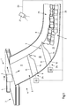
- Fig. 3 is the detail of the sorting device 1 of the Fig. 1 shown in a top view.
- the finger elements 16 of the upper guide device 9 are arranged at different heights. While the left finger elements 16 are arranged in a lower position, the right finger element 16 is arranged in an upper position.
- the other finger elements 16 are provided in different positions between the upper and the lower position, the finger elements 16 being arranged higher the further to the right the finger elements 16 are arranged. In this area, the guide device 9 is consequently inclined to the left.
- the lower free end 14 of the guide device 9 is also arranged in a wave shape.
- the piece goods 2 slide to the side the more the corresponding area of the guide device 9 is inclined to the corresponding side of the slide 4.
- the path that the piece goods 2 takes along the slide 4 is indicated by the arrows with a solid line.
- the piece goods 2 guided somewhat to the side by the upper guide device 9 reaches the lower guide device 10.
- the left two finger elements 16 are arranged in the lower position, while the right three finger elements 16 in the are arranged in the upper position.
- the finger elements 16 provided between them are arranged between the lower position and the upper position, with the right finger element 16 of two adjacent finger elements 16 always being arranged higher than the left finger element 16.
- the guide device 10 is designed to be wave-shaped transversely to the slide 4, with one for area inclined to the left, which is arranged further to the left than the area inclined to the left of the upper guide device 9.
- the piece goods 2 can not only be directed to the side, the piece goods 2 can alternatively or additionally be guided in the vertical direction, namely in particular upwards onto piece goods 2 which have already been stored, so as to form a stack 25 of piece goods 2 which takes up less space as only piece goods 2 arranged next to each other Fig. 3 merely illustrated by way of example using a further piece goods 2, which is deflected less far to the left by the first guide device 9 - for whatever reasons - than the piece goods 2 which follow the solid arrows.
- This General cargo 2 follows the arrow shown in dashed lines and therefore passes the lower guide device 10 at a point at which the finger elements 16 of the lower guide device 10 are at least substantially arranged in the upper position.
- the piece goods 2 are directed onto piece goods 2 which have already been stored and are arranged in front of the corresponding section of the lower guide device 10.
- the piece goods 2 consequently form a space-saving stack 25 of piece goods 2.
- a sorting device 1 ' is shown, which the sorting device of Fig. 1 is similar, which is why the same reference numerals are used for the same components.
- An essential difference between the sorting devices 1, 1 ' relates to the chute 4, 4', in particular the chute bottom 6, 6 '.
- the slide 4 ' is also designed as a box slide with lateral side walls 8', but the slide bottom sections 11 ', 12', 13 'each have a constant inclination.
- the slide floor sections 11 ', 12', 13 ' are therefore flat and can have the same inclination or different inclinations to the horizontal.
- the slide 4 Fig. 1 On the other hand, the inclination of each slide bottom portion 11, 12, 13 gradually and smoothly changes from the upper end to the lower end of the slide bottom portion 11, 12, 13.
- the three slide bottom sections 11 ', 12', 13 ' are not arranged in alignment with one another, as is at least approximately the case with the slide Fig. 1 the case is.
- a significantly greater height offset is provided between the adjacent slide floor sections 11 ', 12', 13 ', which results in a jump for the piece goods 2 to be sorted between the respective adjacent slide floor sections 11', 12 ', 13'.
- the guide devices 9 ', 10' provided between the slide bottom sections 11 ', 12', 13 ' may or may not reduce the jump for the piece goods 2, depending on their position. According to the slide 4 Fig.
- a steady or at least substantially uniform course of the inclination from one slide bottom section 11, 12 via a guide device 9, 10 to the next slide bottom section 12, 13 can be achieved if the finger elements 16 of the guide device 9, 10 are arranged in the lower position, which can also be supported by a curvature of the finger elements 16 '.
- the guide devices 9 ', 10' shown are only arranged at a constant height transversely to the slide 4 'for the sake of simplicity. Since the guiding devices 9 ', 10' also have a number of finger elements 16 'which are height-adjustable relative to one another, the guiding devices 9', 10 'could also have different inclinations at different points transverse to the slide 4'. If necessary, the principles already described and the finger elements that have also already been described can be used. Alternatively, finger elements could also be used, the curvature of which does not change during the height adjustment, but which are rigid in this respect. The finger elements can then be pivoted up and down about a preferably horizontal axis. Because appropriate finger elements for the specialist are to be provided, no further description of corresponding finger elements is required in the present case.
- the upper guide device 9 ' is arranged in a lower or near the lower position in order to reduce the jump of the piece goods 2 and thus to prevent or at least reduce damage.
- the lower guide device 10 ' is in an upper position or is considerably raised compared to the position of the upper guide device 9'.
- further piece goods 2 passing the lower guide device 10 ' are directed onto piece goods 2 already stored in the chute 4' and form a stack 25 there.
- the slide 4 'according to Fig. 4 as well as the slide 4 according to Fig. 1 that, if necessary, the upper or lower guide device 9, 9 ', 10, 10' can be dispensed with.
- the more control devices are provided, the higher the expenditure on equipment and control technology.
- the piece goods 2 can be guided more precisely, flexibly and comprehensively along the chute 4, 4 'in the case of a plurality of guide devices.
- the finger element 16 comprises two flank elements 26 which, in the finger element 16 shown and in this respect preferred, run jointly from an end 19 of the finger element 16 shown on the left and connected to the slide 4 to the opposite free end 18 of the finger element 16 shown on the right.
- the flank elements 26 continuously approach each other in the direction of the free end 18 until the flank elements 26 merge into one another in the illustrated and preferred finger element 16 at the free end 18 of the finger element 16. Therefore, a tapered finger element 16 tapering in one direction is obtained.
- the webs 27 could be flexible in order to enable the webs 27 to move relative to the flank elements 26.
- the webs 27 are distributed at equal intervals over the length of the finger element 16. However, this is not absolutely necessary.
- the webs 27 run parallel to one another. It is particularly expedient, however, that the webs 27 form an acute angle ⁇ with each of the flank elements 16 on one side and an obtuse angle ⁇ on the opposite side.
- flank elements 26 shown and preferred in this respect are designed to be flexible so that the flank elements 26 can be bent, the finger element 16 being more or less curved, which is particularly the case in FIGS 6A-C is shown.
- the flank elements 16 of a guide device By bending the finger elements 16 of a guide device, the free ends of the finger elements are moved in particular upwards or downwards. Ultimately, this leads to an overall height adjustment of the finger elements, even if these can be firmly connected at one end to the slide or the guide device.
- the flank elements can be formed, for example, from a metal or a plastic. The same applies to the webs, which, however, do not have to be flexible.
- FIG. 6A is the finger element 16 out Fig. 5 shown in an elongated orientation, in which the ends of the flank elements 26 are arranged in a plane E.
- the flank elements 26 are at least substantially symmetrical to one another in this position.
- the upper flank element 26 is displaced relative to the plane E in the direction of the free end of the finger element 16, the finger element 16 curves downward.
- the finger element 16 is adjusted downwards, wherein a finger element 16 can, if necessary, also be adjusted downwards or upwards without a curvature thereof, preferably as a whole.
- flank elements 26 do not necessarily have to be flexible over their entire longitudinal extent, even if this will often be preferred. It is also conceivable for the flank elements to have rigid sections which are pivotally connected to one another, in particular articulated, preferably by means of a hinge. Corresponding flank elements between two webs should have at least one swivel connection.
- the finger element 16 curves according to Figure 6C in an analogous manner upwards when the lower flank element 26 is displaced forwards in the direction of the free end 18 of the finger element 16 with respect to the plane E. In this way, an adjustment of the free end 18 of the finger element 16 as well as an adjustment of the finger element 16 can be achieved downwards.
- the 6A-C can also be seen that the webs 27 between the flank elements 26 incline in opposite directions when the finger element 16 is curved when the finger element 16 is adjusted upwards and downwards.
- a drive unit 24 can be provided to adjust the flank elements 16 analog to the 6A-C .
- Suitable drive units 24, such as linear drives, are known from the prior art.
- flank elements can be provided, for example in order not only to move the finger element up and down, but also to the side. For the sake of simplicity, these are then, in particular evenly, distributed around a longitudinal axis of the finger unit.
- the plurality of flank elements can then converge, in particular with free ends, in a common tip of the finger unit.
- the webs can preferably connect all of the flank elements to one another.
- the flank elements shown and in this respect preferred are strip-shaped. However, a plate-like or rod-like configuration of the flank elements would also be possible, as long as the flank elements enable mutual displacement and curvature of the flank elements.
- a finger element 16 ' is shown as part or in the form of a belt conveyor 28, the finger element 16' forming the support structure 29 of the belt conveyor 28 in the illustrated and preferred embodiment.
- the finger element 16 ' is in principle analogous to that in FIG Fig. 1 shown finger element 16 formed.
- the belt conveyor 28, in particular the free end 30 of the belt conveyor 28, can therefore be adjusted upwards and downwards.
- the belt 31 running around the finger element 16 'along the flank elements 26 follows the adjustment, in particular the curvature of the finger element 16' upwards and downwards.
- the belt 31 runs endlessly around the support structure 29 and thus around the finger unit 16 '.
- the finger element 16 ′ shown and in this respect preferred has a plurality of deflections in the form of deflection rollers 32, 33, 34.
- a deflection roller 32 is at the free end 18 of the finger element 16 'and in each case a further deflection roller 33, 34 at the opposite ends of the flank elements 26.
- the deflection rollers 32, 33, 34 are carried by the support structure 29 of the finger element 16'.
- the belt 31 can be held at least at one point on at least the upper flank element 26 by means of suitable connecting means.
- the belt 31 of the finger element 16 ' can be driven by the weight force acting on a piece goods 2 located on the finger element 16' in order to improve the transport of the piece goods 2 along the finger element 16 '.
- a motor drive of the belt 31 can also be provided in order to forcibly drive the belt 31.
- the belt 31 preferably moves on the top of the finger element 16 'in the direction of the free end 18 of the finger element 16'.
- the drive and the belt 31 can be designed to make the belt 31 slower than the original one To drive the speed of the piece goods 2 or even in the opposite direction.
- the drive 35 acts on the belt 31 via a drive roller 36, which can be adjusted if necessary to tension the belt 31, for example in the longitudinal direction of the finger element 16 '.
- the belt 31 on the belt 31 and on the drive roller 36 can be driven so as to be as slip-free as possible
- Corresponding gears can be provided, which mesh with each other.
- the support structure of the finger element may have further components if necessary.
- the belt 31 of the belt conveyor 28, whether it is driven by a motor or not, can only revolve around a finger element 16 'if necessary, it then being possible for each finger element 16' to have a separate belt 31 if necessary.
- the piece goods 2 can thus be guided very flexibly and differently at different points of the guide device 9, 10.
- the outlay in terms of equipment and control technology is then generally higher.
Landscapes
- Engineering & Computer Science (AREA)
- Mechanical Engineering (AREA)
- Chutes (AREA)
- Discharge Of Articles From Conveyors (AREA)
Claims (14)
- Glissière (4, 4') pour marchandises au détail (2), en particulier des colis et/ou des envois, dotée d'un fond de glissière (6) permettant le glissement vers le bas des marchandises au détail (2), comportant au moins deux sections de fond de glissière (11, 11', 12, 12', 13, 13'), les au moins deux sections de fond de glissière (11, 11', 12, 12', 13, 13') formant entre elles un décalage en hauteur, au moins un dispositif de guidage (9, 9', 10, 10') entre les au moins deux sections de fond de glissière (11, 11', 12, 12', 13, 13') étant prévu pour diriger les marchandises au détail (2) d'une section de fond de glissière (11, 11', 12, 12') vers la prochaine section de fond de glissière (12, 12', 13, 13'), le au moins un dispositif de guidage (9, 9', 10, 10') présentant une extrémité libre (14) à hauteur réglable et orientée en direction de la prochaine section de fond de glissière (12, 12', 13, 13'), le dispositif de guidage (9, 9', 10, 10') présentant, transversalement par rapport au fond de glissière (6), plusieurs éléments en forme de doigts (16, 16') à hauteur réglable, au moins en partie indépendamment l'un de l'autre, et agencés l'un à côté de l'autre, caractérisée en ce que les éléments en forme de doigts (16, 16') portent une bande de matière (17) souple enjambant les espaces intermédiaires entre les éléments en forme de doigts (16, 16') et/ou en ce que les éléments en forme de doigts (16, 16') présentent au moins une bande de matière entourant respectivement au moins un élément en forme de doigt (16, 16') et entraînée en direction longitudinale de l'élément en forme de doigts (16, 16').
- Glissière selon la revendication 1, caractérisée en ce que les extrémités libres (18) des éléments en forme de doigts (16, 16') sont agencées à des hauteurs différentes, en particulier de manière ondulée, transversalement par rapport au fond de glissière (6), et, de préférence, en ce que les extrémités libres (18) des éléments en forme de doigts (16, 16') sont agencées transversalement par rapport au fond de glissière (6), partiellement en une position inférieure, partiellement en une position supérieure et/ou partiellement, notamment entre les deux, dans une position entre la position inférieure et la position supérieure.
- Glissière selon la revendication 1 ou 2, caractérisée en ce que les extrémités libres (18) des éléments en forme de doigts (16, 16') sont susceptibles de pouvoir être déplacées, au moins essentiellement de manière continue, entre une position inférieure et une position supérieure.
- Glissière selon l'une des revendications 1 à 3, caractérisée en ce que les extrémités libres (18) des éléments en forme de doigts (16, 16') sont agencées dans une position inférieure, de préférence pour obtenir une transition uniforme de l'inclinaison du fond de glissière (6) d'une section de fond de glissière (11, 11', 12, 12') vers la prochaine section de fond de glissière (12, 12', 13, 13'), au moins à peu près à la hauteur de la prochaine section de fond de glissière (12, 12', 13, 13'), et/ou dans une position supérieure à une distance verticale déterminée de la prochaine section de fond de glissière (12, 12', 13, 13').
- Glissière selon l'une des revendications 1 à 4, caractérisée en ce que les éléments en forme de doigts (16, 16') présentent respectivement au moins deux éléments de flanc (26) souples s'étendant conjointement dans le sens de la longueur des éléments en forme de doigts (16, 16') jusqu'à l'extrémité libre des éléments en forme de doigts (16, 16') et en ce que les éléments de flanc (26) souples sont reliés ensemble, de manière flexible, en direction longitudinale des éléments en forme de doigts (16, 16') respectivement par une multitude de tiges (27), de sorte que les extrémités libres (18) des éléments en forme de doigts (16, 16') peuvent être déplacées d'une position inférieure en une position supérieure et inversement.
- Glissière selon la revendication 5, caractérisée en ce que les tiges (27) et les éléments de flanc (26) souples associés présentent respectivement un angle aigu α, de préférence entre 10° et 80°, et un angle obtus β, de préférence entre 100° et 170°.
- Glissière selon la revendication 5 ou 6, caractérisée en ce que les éléments de flanc (26) souples des éléments en forme de doigts (16, 16') sont susceptibles de pouvoir être déplacés l'un par rapport à l'autre, respectivement notamment par un dispositif d'entraînement (24), en direction longitudinale des éléments en forme de doigts (16, 16'), de sorte que les éléments en forme de doigts (16, 16') sont plus ou moins courbés l'un par rapport à l'autre par un déplacement des éléments de flanc (26) souples.
- Glissière selon l'une des revendications 1 à 7, caractérisée en ce qu'au moins un capteur (21), de préférence optique, est présent pour la saisie du nombre et/ou du type de certaines marchandises au détail stockées (2), de l'emplacement de certaines marchandises au détail stockées (2), des dimensions de certaines marchandises au détail stockées (2), de l'agencement d'un tas (25) de marchandises au détail stockées (2) et/ou de la forme d'un tas (25) de marchandises au détail stockées (2).
- Glissière selon l'une des revendications 1 à 8, caractérisée en ce que l'on prévoit un dispositif de réglage (22) pour le déplacement de la hauteur des extrémités libres (18) des éléments en forme de doigts (16, 16') en fonction du temps, en fonction du nombre et/ou du type de certaines marchandises au détail stockées (2) et/ou en fonction d'au moins un paramètre détecté par le capteur (21).
- Glissière selon l'une des revendications 1 à 9, caractérisée en ce que l'on prévoit au moins un élément en forme de main, en particulier à hauteur réglable, en ce que le au moins un élément en forme de main porte plusieurs éléments en forme de doigts (16, 16') à hauteur réglable l'un par rapport à l'autre et, en cas de besoin, en ce que le au moins un élément en forme de main est porté par un élément en forme de bras, de préférence à hauteur réglable.
- Glissière selon l'une des revendications 1 à 10, caractérisée en ce que l'on prévoit sur l'extrémité inférieure de la glissière (4, 4') une zone de collecte (20) pour le stockage intermédiaire des marchandises au détail (2).
- Procédé de transport des marchandises au détail (2), en particulier des colis et/ou des envois, le long d'une glissière (4, 4') selon l'une des revendications 1 à 11,- lors duquel les marchandises au détail (2) sont temporairement stockées au niveau de l'extrémité inférieure de la glissière (4, 4'),- lors duquel la hauteur des extrémités libres (18) d'au moins certains éléments en forme de doigts (16, 16'), pendant le stockage intermédiaire des marchandises au détail (2), est déplacée afin de mieux exploiter la largeur de la glissière (4, 4') pour le stockage des marchandises au détail (2), afin d'empiler l'une sur l'autre les marchandises au détail à stocker (2) et/ou afin de réduire la hauteur de chute des marchandises au détail (2) d'une section de fond de glissière (11, 11', 12, 12') vers la prochaine section de fond de glissière (12, 12', 13, 13').
- Procédé selon la revendication 12, lors duquel la hauteur des extrémités libres (18) d'au moins certains éléments en forme de doigts (16, 16') peut être déplacée en hauteur en fonction du temps, en fonction du nombre et/ou du type de certaines marchandises au détail stockées (2), en fonction de l'emplacement de certaines marchandises au détail stockées (2), en fonction des dimensions de certaines marchandises au détail stockées (2), en fonction de l'agencement d'un tas (25) de marchandises au détail stockées (2) et/ou en fonction de la forme d'un tas (25) de marchandises au détail stockées (2).
- Procédé selon la revendication 13, lors duquel le nombre et/ou le type de certaines marchandises au détail stockées (2), l'emplacement de certaines marchandises au détail stockées (2), les dimensions de certaines marchandises au détail stockées (2), l'agencement d'un tas (25) de marchandises au détail stockées (2) et/ou la forme d'un tas (25) de marchandises au détail stockées (2) est détecté(e)/sont détectées avec au moins un capteur (21), de préférence optique et, de préférence, lors duquel le au moins un capteur (21) transmet un signal (23) à un dispositif de réglage (22) pour le déplacement de la hauteur des extrémités libres (18) des éléments en forme de doigts (16, 16') en fonction du signal (23).
Applications Claiming Priority (1)
| Application Number | Priority Date | Filing Date | Title |
|---|---|---|---|
| DE102016109313.0A DE102016109313A1 (de) | 2016-05-20 | 2016-05-20 | Rutsche für Stückgut und Verfahren zur Verwendung einer solchen Rutsche |
Publications (2)
| Publication Number | Publication Date |
|---|---|
| EP3248914A1 EP3248914A1 (fr) | 2017-11-29 |
| EP3248914B1 true EP3248914B1 (fr) | 2020-02-26 |
Family
ID=58464301
Family Applications (1)
| Application Number | Title | Priority Date | Filing Date |
|---|---|---|---|
| EP17163845.5A Active EP3248914B1 (fr) | 2016-05-20 | 2017-03-30 | Glissière pour marchandise de détail et procédé d'utilisation d'une telle glissière |
Country Status (4)
| Country | Link |
|---|---|
| US (1) | US9969554B2 (fr) |
| EP (1) | EP3248914B1 (fr) |
| CN (1) | CN107399550B (fr) |
| DE (1) | DE102016109313A1 (fr) |
Families Citing this family (18)
| Publication number | Priority date | Publication date | Assignee | Title |
|---|---|---|---|---|
| DE102015210344A1 (de) * | 2015-06-04 | 2016-12-08 | Siemens Aktiengesellschaft | Transportrutsche mit Breitenverteilungsvorrichtung |
| EP3689795B1 (fr) * | 2019-01-31 | 2024-12-25 | Amazon Technologies, Inc. | Goulotte pour emballages |
| US11130634B1 (en) * | 2019-06-27 | 2021-09-28 | Material Handling Systems, Inc. | Rejection chute for a conveyor system |
| US11027923B1 (en) * | 2019-09-20 | 2021-06-08 | Amazon Technologies, Inc. | Chute accumulation system |
| CN110817363B (zh) * | 2019-11-06 | 2021-11-12 | 徐州欧百瑞智能设备有限公司 | 一种智能设备生产线零件连续传送导向挡板 |
| US10919702B1 (en) * | 2020-04-29 | 2021-02-16 | Eugene Zoltan Berta | Aerial roof height item receiving chute |
| CN111872343B (zh) * | 2020-07-27 | 2022-02-18 | 共享智能铸造产业创新中心有限公司 | 落管调度系统及其管理控制方法 |
| DE102020125503A1 (de) * | 2020-09-30 | 2022-03-31 | Deutsche Post Ag | Beladevorrichtung und Verfahren zum Beladen eines Behälters mit Packstücken |
| DE102020126448B4 (de) * | 2020-10-08 | 2022-11-10 | Deutsche Post Ag | Verfahren und Vorrichtung zum Beladen von Behältern mit Packstücken |
| PL73049Y1 (pl) * | 2020-12-15 | 2023-06-26 | Univ Technologiczno Przyrodniczy Im Jana I Jedrzeja Sniadeckich W Bydgoszczy | Ześlizg dla urządzenia sortującego |
| US11453556B2 (en) * | 2021-01-05 | 2022-09-27 | Impact Automation, Inc. | Stepped accumulation chute |
| ES3029809T3 (en) * | 2021-02-11 | 2025-06-25 | Trinovate B V | A sorting device |
| DE202022003350U1 (de) * | 2021-03-16 | 2026-02-20 | Interroll Holding Ag | Förderanordnung |
| US12486121B2 (en) * | 2021-04-09 | 2025-12-02 | Dexterity, Inc. | Robotically-controlled structure to regulate item flow |
| US11827465B1 (en) * | 2021-08-10 | 2023-11-28 | Amazon Technologies, Inc. | Self-balancing filling system |
| US12180007B2 (en) | 2022-03-15 | 2024-12-31 | Talos Engineered Products, LLC | Modular chute system |
| DE102023107764B3 (de) * | 2023-03-28 | 2024-06-20 | Deutsche Post Ag | Sortierendstelle und Logistiksorter |
| CN116891095B (zh) * | 2023-07-20 | 2025-12-09 | 上海交通大学 | 颗粒状农作物逐粒有序排列装置 |
Citations (3)
| Publication number | Priority date | Publication date | Assignee | Title |
|---|---|---|---|---|
| DE3612076A1 (de) * | 1985-01-16 | 1987-10-15 | Bsn Sa | Vorrichtung und anlage zum optischen sichten von unreinem glasbruch |
| EP0521541A1 (fr) * | 1991-07-05 | 1993-01-07 | Vanderlande Industries Nederland B.V. | Colonne de descente munie de moyens de retardement |
| US20160101957A1 (en) * | 2014-10-13 | 2016-04-14 | Laitram, L.L.C. | Missort prevention system in a conveying system |
Family Cites Families (16)
| Publication number | Priority date | Publication date | Assignee | Title |
|---|---|---|---|---|
| DE907516C (de) * | 1951-03-20 | 1954-03-25 | Simon Ltd Henry | Rutsche fuer Stueckgueter, insbesondere Sackrutsche |
| US2821278A (en) * | 1956-04-25 | 1958-01-28 | Arthur E Paschal | Ear and shelled corn handling device |
| US3187872A (en) * | 1963-02-18 | 1965-06-08 | Frederick L Hill | Tomato harvester |
| US3738507A (en) * | 1971-09-13 | 1973-06-12 | Sunkist Growers Inc | Bin for accumulating spherical articles |
| US3841461A (en) * | 1972-07-20 | 1974-10-15 | Univ California | Singulator |
| US4130193A (en) * | 1977-04-25 | 1978-12-19 | Bourgeois Ronald D | Transfer system for conveyor systems |
| DE4017128A1 (de) * | 1990-05-28 | 1991-12-05 | Seichter Gmbh | Einrichtung zum sortieren von glasbruchstuecken |
| DE4041268A1 (de) * | 1990-12-21 | 1992-06-25 | Gao Ges Automation Org | Vorrichtung zum umlenken von duennem blattgut |
| DE4415788A1 (de) * | 1994-05-05 | 1995-11-09 | Licentia Gmbh | Schwenkflügelweiche |
| US6095314A (en) * | 1998-07-17 | 2000-08-01 | Mantissa Corporation | Multi-cell chute for a tilt tray sorter |
| JP2001315928A (ja) * | 2000-05-10 | 2001-11-13 | Toyo Kanetsu Kk | 仕分装置のシュート構造 |
| US7306086B2 (en) * | 2004-09-27 | 2007-12-11 | Laitram, L.L.C. | Sorting system using a roller-top conveyor belt |
| US8607964B2 (en) * | 2008-05-15 | 2013-12-17 | Fluor Technologies Corporation | Adjustable conveyor chute |
| DE102010049281B4 (de) * | 2010-10-22 | 2014-05-08 | Beumer Gmbh & Co. Kg | Schwerkraftrutsche |
| EP2794435B1 (fr) * | 2011-12-22 | 2016-04-27 | Crisplant A/S | Système de chute avec angle d'inclinaison règlable |
| DE102015116720B4 (de) * | 2015-10-01 | 2019-03-07 | Deutsche Post Ag | Verfahren und Vorrichtung zum Fördern von Stückgütern von einem Stapel oder Haufen |
-
2016
- 2016-05-20 DE DE102016109313.0A patent/DE102016109313A1/de active Pending
-
2017
- 2017-03-30 EP EP17163845.5A patent/EP3248914B1/fr active Active
- 2017-05-15 US US15/595,206 patent/US9969554B2/en active Active
- 2017-05-19 CN CN201710360830.9A patent/CN107399550B/zh active Active
Patent Citations (3)
| Publication number | Priority date | Publication date | Assignee | Title |
|---|---|---|---|---|
| DE3612076A1 (de) * | 1985-01-16 | 1987-10-15 | Bsn Sa | Vorrichtung und anlage zum optischen sichten von unreinem glasbruch |
| EP0521541A1 (fr) * | 1991-07-05 | 1993-01-07 | Vanderlande Industries Nederland B.V. | Colonne de descente munie de moyens de retardement |
| US20160101957A1 (en) * | 2014-10-13 | 2016-04-14 | Laitram, L.L.C. | Missort prevention system in a conveying system |
Also Published As
| Publication number | Publication date |
|---|---|
| US20170334648A1 (en) | 2017-11-23 |
| EP3248914A1 (fr) | 2017-11-29 |
| CN107399550B (zh) | 2019-09-06 |
| US9969554B2 (en) | 2018-05-15 |
| DE102016109313A1 (de) | 2017-11-23 |
| CN107399550A (zh) | 2017-11-28 |
Similar Documents
| Publication | Publication Date | Title |
|---|---|---|
| EP3248914A1 (fr) | Glissière pour marchandise de détail et procédé d'utilisation d'une telle glissière | |
| EP3246272B1 (fr) | Glissière et dispositif de tri et procédé de tri de marchandise au détail | |
| DE4100769C2 (de) | Vorrichtung zum Fördern von Produkten in einer Verpackungsmaschine | |
| EP3248913B1 (fr) | Convoyeur de singularisation et procédé de transport destinés à séparer une marchandise de détail le long d'au moins une bande de transport | |
| DE60311778T2 (de) | Zurückziehbare übergabeeinrichtung für eine dosiervorrichtung | |
| EP3115322B1 (fr) | Procede et dispositif destines a la depalettisation de pneus | |
| DE102020126448B4 (de) | Verfahren und Vorrichtung zum Beladen von Behältern mit Packstücken | |
| DE102013202872A1 (de) | Verfahren und Vorrichtung zum Ausrichten und/oder Gruppieren von Artikeln, Stückgütern oder Gebinden | |
| WO2007093383A1 (fr) | Procédé et automate à bande centrale pour le remplissage DE récipients de transport dans un système d'expédition de commandes | |
| EP3978398B1 (fr) | Dispositif de chargement et procédé de chargement d'un contenant pour colis | |
| DE102015113021A1 (de) | Gruppieren von Gütern | |
| EP3224164B1 (fr) | Procédé pour réunir des produits à emballer et dispositif de transport de produits à emballer | |
| DE102011015670A1 (de) | Speichervorrichtung | |
| DE102010012597A1 (de) | Einrichtung zum Transportieren von Objekten | |
| DE102020116880A1 (de) | Verfahren und Vorrichtung zum Entladen eines Packstücke aufweisenden Behälters | |
| EP2859802B1 (fr) | Dispositif et procédé de transport et de tri d'articles à fumer | |
| DE19501637C2 (de) | Palettiervorrichtung | |
| WO2024078662A1 (fr) | Dispositif de transport et de séparation de pièces | |
| EP0869095B1 (fr) | Empileur | |
| EP3106412B1 (fr) | Groupement de marchandises | |
| EP2660169A1 (fr) | Convoyeur linéaire et procédé d'acheminement pour des éléments de liaison | |
| EP2746198B1 (fr) | Utilisation d'un dispositif de transport | |
| DE102009031117B3 (de) | Vorrichtung und Verfahren zur stapelförmigen Ablage von bogenförmigen Substraten | |
| DE102010047562A1 (de) | Bandförderer mit längenveränderbarer Bandunterstützung | |
| EP1522509B1 (fr) | Appareil d'empilage de produits plats |
Legal Events
| Date | Code | Title | Description |
|---|---|---|---|
| PUAI | Public reference made under article 153(3) epc to a published international application that has entered the european phase |
Free format text: ORIGINAL CODE: 0009012 |
|
| STAA | Information on the status of an ep patent application or granted ep patent |
Free format text: STATUS: THE APPLICATION HAS BEEN PUBLISHED |
|
| AK | Designated contracting states |
Kind code of ref document: A1 Designated state(s): AL AT BE BG CH CY CZ DE DK EE ES FI FR GB GR HR HU IE IS IT LI LT LU LV MC MK MT NL NO PL PT RO RS SE SI SK SM TR |
|
| AX | Request for extension of the european patent |
Extension state: BA ME |
|
| STAA | Information on the status of an ep patent application or granted ep patent |
Free format text: STATUS: REQUEST FOR EXAMINATION WAS MADE |
|
| 17P | Request for examination filed |
Effective date: 20180131 |
|
| RBV | Designated contracting states (corrected) |
Designated state(s): AL AT BE BG CH CY CZ DE DK EE ES FI FR GB GR HR HU IE IS IT LI LT LU LV MC MK MT NL NO PL PT RO RS SE SI SK SM TR |
|
| STAA | Information on the status of an ep patent application or granted ep patent |
Free format text: STATUS: EXAMINATION IS IN PROGRESS |
|
| 17Q | First examination report despatched |
Effective date: 20180410 |
|
| GRAP | Despatch of communication of intention to grant a patent |
Free format text: ORIGINAL CODE: EPIDOSNIGR1 |
|
| STAA | Information on the status of an ep patent application or granted ep patent |
Free format text: STATUS: GRANT OF PATENT IS INTENDED |
|
| INTG | Intention to grant announced |
Effective date: 20190910 |
|
| GRAS | Grant fee paid |
Free format text: ORIGINAL CODE: EPIDOSNIGR3 |
|
| GRAA | (expected) grant |
Free format text: ORIGINAL CODE: 0009210 |
|
| STAA | Information on the status of an ep patent application or granted ep patent |
Free format text: STATUS: THE PATENT HAS BEEN GRANTED |
|
| AK | Designated contracting states |
Kind code of ref document: B1 Designated state(s): AL AT BE BG CH CY CZ DE DK EE ES FI FR GB GR HR HU IE IS IT LI LT LU LV MC MK MT NL NO PL PT RO RS SE SI SK SM TR |
|
| REG | Reference to a national code |
Ref country code: GB Ref legal event code: FG4D Free format text: NOT ENGLISH |
|
| REG | Reference to a national code |
Ref country code: CH Ref legal event code: EP |
|
| REG | Reference to a national code |
Ref country code: DE Ref legal event code: R096 Ref document number: 502017003931 Country of ref document: DE |
|
| REG | Reference to a national code |
Ref country code: AT Ref legal event code: REF Ref document number: 1237382 Country of ref document: AT Kind code of ref document: T Effective date: 20200315 |
|
| REG | Reference to a national code |
Ref country code: IE Ref legal event code: FG4D Free format text: LANGUAGE OF EP DOCUMENT: GERMAN |
|
| PG25 | Lapsed in a contracting state [announced via postgrant information from national office to epo] |
Ref country code: RS Free format text: LAPSE BECAUSE OF FAILURE TO SUBMIT A TRANSLATION OF THE DESCRIPTION OR TO PAY THE FEE WITHIN THE PRESCRIBED TIME-LIMIT Effective date: 20200226 Ref country code: FI Free format text: LAPSE BECAUSE OF FAILURE TO SUBMIT A TRANSLATION OF THE DESCRIPTION OR TO PAY THE FEE WITHIN THE PRESCRIBED TIME-LIMIT Effective date: 20200226 Ref country code: NO Free format text: LAPSE BECAUSE OF FAILURE TO SUBMIT A TRANSLATION OF THE DESCRIPTION OR TO PAY THE FEE WITHIN THE PRESCRIBED TIME-LIMIT Effective date: 20200526 |
|
| REG | Reference to a national code |
Ref country code: NL Ref legal event code: MP Effective date: 20200226 |
|
| REG | Reference to a national code |
Ref country code: LT Ref legal event code: MG4D |
|
| PG25 | Lapsed in a contracting state [announced via postgrant information from national office to epo] |
Ref country code: SE Free format text: LAPSE BECAUSE OF FAILURE TO SUBMIT A TRANSLATION OF THE DESCRIPTION OR TO PAY THE FEE WITHIN THE PRESCRIBED TIME-LIMIT Effective date: 20200226 Ref country code: LV Free format text: LAPSE BECAUSE OF FAILURE TO SUBMIT A TRANSLATION OF THE DESCRIPTION OR TO PAY THE FEE WITHIN THE PRESCRIBED TIME-LIMIT Effective date: 20200226 Ref country code: GR Free format text: LAPSE BECAUSE OF FAILURE TO SUBMIT A TRANSLATION OF THE DESCRIPTION OR TO PAY THE FEE WITHIN THE PRESCRIBED TIME-LIMIT Effective date: 20200527 Ref country code: HR Free format text: LAPSE BECAUSE OF FAILURE TO SUBMIT A TRANSLATION OF THE DESCRIPTION OR TO PAY THE FEE WITHIN THE PRESCRIBED TIME-LIMIT Effective date: 20200226 Ref country code: IS Free format text: LAPSE BECAUSE OF FAILURE TO SUBMIT A TRANSLATION OF THE DESCRIPTION OR TO PAY THE FEE WITHIN THE PRESCRIBED TIME-LIMIT Effective date: 20200626 Ref country code: BG Free format text: LAPSE BECAUSE OF FAILURE TO SUBMIT A TRANSLATION OF THE DESCRIPTION OR TO PAY THE FEE WITHIN THE PRESCRIBED TIME-LIMIT Effective date: 20200526 |
|
| PG25 | Lapsed in a contracting state [announced via postgrant information from national office to epo] |
Ref country code: NL Free format text: LAPSE BECAUSE OF FAILURE TO SUBMIT A TRANSLATION OF THE DESCRIPTION OR TO PAY THE FEE WITHIN THE PRESCRIBED TIME-LIMIT Effective date: 20200226 |
|
| PG25 | Lapsed in a contracting state [announced via postgrant information from national office to epo] |
Ref country code: CZ Free format text: LAPSE BECAUSE OF FAILURE TO SUBMIT A TRANSLATION OF THE DESCRIPTION OR TO PAY THE FEE WITHIN THE PRESCRIBED TIME-LIMIT Effective date: 20200226 Ref country code: SK Free format text: LAPSE BECAUSE OF FAILURE TO SUBMIT A TRANSLATION OF THE DESCRIPTION OR TO PAY THE FEE WITHIN THE PRESCRIBED TIME-LIMIT Effective date: 20200226 Ref country code: RO Free format text: LAPSE BECAUSE OF FAILURE TO SUBMIT A TRANSLATION OF THE DESCRIPTION OR TO PAY THE FEE WITHIN THE PRESCRIBED TIME-LIMIT Effective date: 20200226 Ref country code: ES Free format text: LAPSE BECAUSE OF FAILURE TO SUBMIT A TRANSLATION OF THE DESCRIPTION OR TO PAY THE FEE WITHIN THE PRESCRIBED TIME-LIMIT Effective date: 20200226 Ref country code: LT Free format text: LAPSE BECAUSE OF FAILURE TO SUBMIT A TRANSLATION OF THE DESCRIPTION OR TO PAY THE FEE WITHIN THE PRESCRIBED TIME-LIMIT Effective date: 20200226 Ref country code: PT Free format text: LAPSE BECAUSE OF FAILURE TO SUBMIT A TRANSLATION OF THE DESCRIPTION OR TO PAY THE FEE WITHIN THE PRESCRIBED TIME-LIMIT Effective date: 20200719 Ref country code: DK Free format text: LAPSE BECAUSE OF FAILURE TO SUBMIT A TRANSLATION OF THE DESCRIPTION OR TO PAY THE FEE WITHIN THE PRESCRIBED TIME-LIMIT Effective date: 20200226 Ref country code: EE Free format text: LAPSE BECAUSE OF FAILURE TO SUBMIT A TRANSLATION OF THE DESCRIPTION OR TO PAY THE FEE WITHIN THE PRESCRIBED TIME-LIMIT Effective date: 20200226 Ref country code: SM Free format text: LAPSE BECAUSE OF FAILURE TO SUBMIT A TRANSLATION OF THE DESCRIPTION OR TO PAY THE FEE WITHIN THE PRESCRIBED TIME-LIMIT Effective date: 20200226 |
|
| REG | Reference to a national code |
Ref country code: CH Ref legal event code: PL |
|
| REG | Reference to a national code |
Ref country code: DE Ref legal event code: R097 Ref document number: 502017003931 Country of ref document: DE |
|
| PG25 | Lapsed in a contracting state [announced via postgrant information from national office to epo] |
Ref country code: MC Free format text: LAPSE BECAUSE OF FAILURE TO SUBMIT A TRANSLATION OF THE DESCRIPTION OR TO PAY THE FEE WITHIN THE PRESCRIBED TIME-LIMIT Effective date: 20200226 |
|
| REG | Reference to a national code |
Ref country code: BE Ref legal event code: MM Effective date: 20200331 |
|
| PG25 | Lapsed in a contracting state [announced via postgrant information from national office to epo] |
Ref country code: LU Free format text: LAPSE BECAUSE OF NON-PAYMENT OF DUE FEES Effective date: 20200330 |
|
| PLBE | No opposition filed within time limit |
Free format text: ORIGINAL CODE: 0009261 |
|
| STAA | Information on the status of an ep patent application or granted ep patent |
Free format text: STATUS: NO OPPOSITION FILED WITHIN TIME LIMIT |
|
| PG25 | Lapsed in a contracting state [announced via postgrant information from national office to epo] |
Ref country code: LI Free format text: LAPSE BECAUSE OF NON-PAYMENT OF DUE FEES Effective date: 20200331 Ref country code: IE Free format text: LAPSE BECAUSE OF NON-PAYMENT OF DUE FEES Effective date: 20200330 Ref country code: IT Free format text: LAPSE BECAUSE OF FAILURE TO SUBMIT A TRANSLATION OF THE DESCRIPTION OR TO PAY THE FEE WITHIN THE PRESCRIBED TIME-LIMIT Effective date: 20200226 Ref country code: CH Free format text: LAPSE BECAUSE OF NON-PAYMENT OF DUE FEES Effective date: 20200331 |
|
| 26N | No opposition filed |
Effective date: 20201127 |
|
| PG25 | Lapsed in a contracting state [announced via postgrant information from national office to epo] |
Ref country code: PL Free format text: LAPSE BECAUSE OF FAILURE TO SUBMIT A TRANSLATION OF THE DESCRIPTION OR TO PAY THE FEE WITHIN THE PRESCRIBED TIME-LIMIT Effective date: 20200226 Ref country code: SI Free format text: LAPSE BECAUSE OF FAILURE TO SUBMIT A TRANSLATION OF THE DESCRIPTION OR TO PAY THE FEE WITHIN THE PRESCRIBED TIME-LIMIT Effective date: 20200226 Ref country code: BE Free format text: LAPSE BECAUSE OF NON-PAYMENT OF DUE FEES Effective date: 20200331 |
|
| PG25 | Lapsed in a contracting state [announced via postgrant information from national office to epo] |
Ref country code: TR Free format text: LAPSE BECAUSE OF FAILURE TO SUBMIT A TRANSLATION OF THE DESCRIPTION OR TO PAY THE FEE WITHIN THE PRESCRIBED TIME-LIMIT Effective date: 20200226 Ref country code: MT Free format text: LAPSE BECAUSE OF FAILURE TO SUBMIT A TRANSLATION OF THE DESCRIPTION OR TO PAY THE FEE WITHIN THE PRESCRIBED TIME-LIMIT Effective date: 20200226 Ref country code: CY Free format text: LAPSE BECAUSE OF FAILURE TO SUBMIT A TRANSLATION OF THE DESCRIPTION OR TO PAY THE FEE WITHIN THE PRESCRIBED TIME-LIMIT Effective date: 20200226 |
|
| PG25 | Lapsed in a contracting state [announced via postgrant information from national office to epo] |
Ref country code: MK Free format text: LAPSE BECAUSE OF FAILURE TO SUBMIT A TRANSLATION OF THE DESCRIPTION OR TO PAY THE FEE WITHIN THE PRESCRIBED TIME-LIMIT Effective date: 20200226 Ref country code: AL Free format text: LAPSE BECAUSE OF FAILURE TO SUBMIT A TRANSLATION OF THE DESCRIPTION OR TO PAY THE FEE WITHIN THE PRESCRIBED TIME-LIMIT Effective date: 20200226 |
|
| REG | Reference to a national code |
Ref country code: AT Ref legal event code: MM01 Ref document number: 1237382 Country of ref document: AT Kind code of ref document: T Effective date: 20220330 |
|
| P01 | Opt-out of the competence of the unified patent court (upc) registered |
Effective date: 20230517 |
|
| PG25 | Lapsed in a contracting state [announced via postgrant information from national office to epo] |
Ref country code: AT Free format text: LAPSE BECAUSE OF NON-PAYMENT OF DUE FEES Effective date: 20220330 |
|
| PGFP | Annual fee paid to national office [announced via postgrant information from national office to epo] |
Ref country code: GB Payment date: 20260326 Year of fee payment: 10 |
|
| PGFP | Annual fee paid to national office [announced via postgrant information from national office to epo] |
Ref country code: DE Payment date: 20260327 Year of fee payment: 10 |
|
| PGFP | Annual fee paid to national office [announced via postgrant information from national office to epo] |
Ref country code: FR Payment date: 20260326 Year of fee payment: 10 |