EP2031236A2 - Unité d'alimentation en carburant - Google Patents
Unité d'alimentation en carburant Download PDFInfo
- Publication number
- EP2031236A2 EP2031236A2 EP08105134A EP08105134A EP2031236A2 EP 2031236 A2 EP2031236 A2 EP 2031236A2 EP 08105134 A EP08105134 A EP 08105134A EP 08105134 A EP08105134 A EP 08105134A EP 2031236 A2 EP2031236 A2 EP 2031236A2
- Authority
- EP
- European Patent Office
- Prior art keywords
- fuel
- frame
- filter
- delivery unit
- unit according
- Prior art date
- Legal status (The legal status is an assumption and is not a legal conclusion. Google has not performed a legal analysis and makes no representation as to the accuracy of the status listed.)
- Withdrawn
Links
Images

Classifications
-
- F—MECHANICAL ENGINEERING; LIGHTING; HEATING; WEAPONS; BLASTING
- F02—COMBUSTION ENGINES; HOT-GAS OR COMBUSTION-PRODUCT ENGINE PLANTS
- F02M—SUPPLYING COMBUSTION ENGINES IN GENERAL WITH COMBUSTIBLE MIXTURES OR CONSTITUENTS THEREOF
- F02M37/00—Apparatus or systems for feeding liquid fuel from storage containers to carburettors or fuel-injection apparatus; Arrangements for purifying liquid fuel specially adapted for, or arranged on, internal-combustion engines
- F02M37/02—Feeding by means of suction apparatus, e.g. by air flow through carburettors
- F02M37/025—Feeding by means of a liquid fuel-driven jet pump
-
- F—MECHANICAL ENGINEERING; LIGHTING; HEATING; WEAPONS; BLASTING
- F02—COMBUSTION ENGINES; HOT-GAS OR COMBUSTION-PRODUCT ENGINE PLANTS
- F02M—SUPPLYING COMBUSTION ENGINES IN GENERAL WITH COMBUSTIBLE MIXTURES OR CONSTITUENTS THEREOF
- F02M37/00—Apparatus or systems for feeding liquid fuel from storage containers to carburettors or fuel-injection apparatus; Arrangements for purifying liquid fuel specially adapted for, or arranged on, internal-combustion engines
- F02M37/04—Feeding by means of driven pumps
- F02M37/08—Feeding by means of driven pumps electrically driven
- F02M37/10—Feeding by means of driven pumps electrically driven submerged in fuel, e.g. in reservoir
- F02M37/106—Feeding by means of driven pumps electrically driven submerged in fuel, e.g. in reservoir the pump being installed in a sub-tank
-
- F—MECHANICAL ENGINEERING; LIGHTING; HEATING; WEAPONS; BLASTING
- F02—COMBUSTION ENGINES; HOT-GAS OR COMBUSTION-PRODUCT ENGINE PLANTS
- F02M—SUPPLYING COMBUSTION ENGINES IN GENERAL WITH COMBUSTIBLE MIXTURES OR CONSTITUENTS THEREOF
- F02M37/00—Apparatus or systems for feeding liquid fuel from storage containers to carburettors or fuel-injection apparatus; Arrangements for purifying liquid fuel specially adapted for, or arranged on, internal-combustion engines
- F02M37/22—Arrangements for purifying liquid fuel specially adapted for, or arranged on, internal-combustion engines, e.g. arrangements in the feeding system
- F02M37/32—Arrangements for purifying liquid fuel specially adapted for, or arranged on, internal-combustion engines, e.g. arrangements in the feeding system characterised by filters or filter arrangements
- F02M37/34—Arrangements for purifying liquid fuel specially adapted for, or arranged on, internal-combustion engines, e.g. arrangements in the feeding system characterised by filters or filter arrangements by the filter structure, e.g. honeycomb, mesh or fibrous
-
- F—MECHANICAL ENGINEERING; LIGHTING; HEATING; WEAPONS; BLASTING
- F02—COMBUSTION ENGINES; HOT-GAS OR COMBUSTION-PRODUCT ENGINE PLANTS
- F02M—SUPPLYING COMBUSTION ENGINES IN GENERAL WITH COMBUSTIBLE MIXTURES OR CONSTITUENTS THEREOF
- F02M37/00—Apparatus or systems for feeding liquid fuel from storage containers to carburettors or fuel-injection apparatus; Arrangements for purifying liquid fuel specially adapted for, or arranged on, internal-combustion engines
- F02M37/22—Arrangements for purifying liquid fuel specially adapted for, or arranged on, internal-combustion engines, e.g. arrangements in the feeding system
- F02M37/32—Arrangements for purifying liquid fuel specially adapted for, or arranged on, internal-combustion engines, e.g. arrangements in the feeding system characterised by filters or filter arrangements
- F02M37/44—Filters structurally associated with pumps
-
- F—MECHANICAL ENGINEERING; LIGHTING; HEATING; WEAPONS; BLASTING
- F02—COMBUSTION ENGINES; HOT-GAS OR COMBUSTION-PRODUCT ENGINE PLANTS
- F02M—SUPPLYING COMBUSTION ENGINES IN GENERAL WITH COMBUSTIBLE MIXTURES OR CONSTITUENTS THEREOF
- F02M37/00—Apparatus or systems for feeding liquid fuel from storage containers to carburettors or fuel-injection apparatus; Arrangements for purifying liquid fuel specially adapted for, or arranged on, internal-combustion engines
- F02M37/22—Arrangements for purifying liquid fuel specially adapted for, or arranged on, internal-combustion engines, e.g. arrangements in the feeding system
- F02M37/32—Arrangements for purifying liquid fuel specially adapted for, or arranged on, internal-combustion engines, e.g. arrangements in the feeding system characterised by filters or filter arrangements
- F02M37/50—Filters arranged in or on fuel tanks
-
- F—MECHANICAL ENGINEERING; LIGHTING; HEATING; WEAPONS; BLASTING
- F02—COMBUSTION ENGINES; HOT-GAS OR COMBUSTION-PRODUCT ENGINE PLANTS
- F02M—SUPPLYING COMBUSTION ENGINES IN GENERAL WITH COMBUSTIBLE MIXTURES OR CONSTITUENTS THEREOF
- F02M37/00—Apparatus or systems for feeding liquid fuel from storage containers to carburettors or fuel-injection apparatus; Arrangements for purifying liquid fuel specially adapted for, or arranged on, internal-combustion engines
- F02M37/22—Arrangements for purifying liquid fuel specially adapted for, or arranged on, internal-combustion engines, e.g. arrangements in the feeding system
- F02M37/32—Arrangements for purifying liquid fuel specially adapted for, or arranged on, internal-combustion engines, e.g. arrangements in the feeding system characterised by filters or filter arrangements
- F02M37/42—Installation or removal of filters
Definitions
- the invention relates to a fuel delivery unit having a surge tank to be arranged in a fuel tank of a motor vehicle, in which a fuel pump is provided for delivering an internal combustion engine fuel pump, with a suction jet pump for delivering fuel from the fuel tank into the surge chamber, the suction jet pump housing has at least a first channel for supplying fuel as a propellant to a propulsion jet nozzle of the ejector, and at least one second channel for supplying fuel from the swirl pot to an inlet channel of the fuel pump.
- Such a fuel delivery unit is from the DE 101 38 838 A1 known.
- the housing of the suction jet pump has a first port, which is connected to the fuel pump, and a second port on which a filter is attached. Fuel is sucked from the swirl pot via the second port and fed via the first port to the inlet channel of the fuel pump.
- the first nozzle also has a portion, is supplied via the funded by the fuel pump fuel as propellant of the ejector.
- the propellant causes fuel to be sucked out of the fuel tank via an intake opening in the housing of the ejector pump and to be conveyed through the mixing tube of the ejector pump into the swirl pot.
- the filter which is plugged onto the second port of the suction jet pump, is vertically aligned for reasons of space in the surge chamber in its longitudinal extent.
- Such filters consist of an elongate filter fabric bag with a connector.
- the support body has the task of ensuring the coarse alignment of the filter and to avoid squeezing the filter fabric, which reduces the effective filter area.
- Such support body usually have a complicated structure, which makes the production more expensive.
- the support body requires additional assembly steps, which increases the cost of producing such a filter.
- the present invention is therefore an object of the invention to provide a fuel delivery unit of the type mentioned, which is inexpensive to manufacture and easy to assemble, in particular, the proper installation of the filter should be guaranteed.
- the object is achieved in that the housing has a perpendicular to the longitudinal axis of a mixing tube of the suction jet pump and integrally connected to the housing frame whose framed surface is covered with filter fabric by the filter fabric is disposed on both sides of the frame, so as one Forming filter, and that the frame in its the suction jet pump-facing region has a disposed between the filter fabric opening, which merges into the at least second channel.
- the integrally connected with the housing of the suction jet pump frame for the filter has the advantage that the pump pre-filter for the fuel pump is now no separate component, which must be manufactured and assembled individually, but can be manufactured in one operation with the housing of the suction jet pump. This reduces the costs of production and assembly. Another advantage is that the frame of the shape of the filter can be specified exactly. A faulty mounting, z. B. wrinkles the filter fabric during installation, is also excluded with the filter according to the invention.
- the filter can be produced with very little effort by the fact that each filter fabric is welded or encapsulated on one side of the frame with this. During encapsulation, the filter fabric is inserted into the injection mold for the frame, so that the injected into the injection mold plastic forms an intimate connection with the filter fabric. In this way, very little filter fabric is needed for the production.
- the cutting of the filter fabric can be minimized by using only one filter fabric, which is stretched in a U-shape over the frame so that it covers both sides of the frame and is welded thereto.
- another embodiment is to arrange a filter fabric on only one side of the frame.
- the second filter fabric solid material is instead arranged so that it forms a cup-shaped housing with the frame, the open side of which is covered by a filter fabric. The advantage is that this eliminates the step of attaching the second filter fabric, thereby reducing the cost of the fuel delivery unit.
- At least one strut in the framed area within the frame.
- the at least one strut serves to increase the stability of the frame.
- the strut prevents the filter fabrics located on either side of the frame from touching each other, which would result in a reduction of the effective filter area.
- the at least one strut can be produced in a particularly simple manner if it is formed integrally with the frame. Since the housing is advantageously produced by means of injection molding, this method is suitable for the production of the at least one strut.
- a star-shaped converging arrangement of the struts on the frame has proven to be advantageous.
- a saving of material can be achieved according to another advantageous embodiment with struts which are formed differently thick along their longitudinal extent. To increase the dimensional stability of the filter fabric, it helps to provide this with a reinforced circumferential edge and to arrange the two filter fabric on both sides of the frame tight.
- the arrangement of the filter fabric on the frame can be achieved in a further embodiment by pressing, Verklipsen, welding or gluing.
- the pressing or clipping is characterized by a particularly low installation costs. While the pressing is already possible with a simple reinforced edge, the clipping requires additional snap hooks, or rest areas, which facilitates the release of the connection, z. B. for maintenance or repair.
- provided struts can be formed according to another embodiment with the reinforced peripheral edge.
- the advantage of the fuel delivery unit according to the invention that the frame dictates the form of the filter particularly true to form, also makes it possible to create a filter, makes optimal use of the available space by the frame is adapted to the filter fabric to the available space.
- the adjustment can be carried out by a curvature of the frame, which aligns the curvature of the frame at the radius of the swirl pot.
- the filter can also have a horizontal orientation or a different angular position.
- the alignment can also take place in the vertical direction in that the frame with the filter fabric has on its upper side a course deviating from the horizontal.
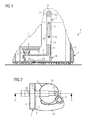
- FIG. 1 shows a fuel tank 1, in which a fuel delivery unit 2 is used.
- the fuel delivery unit 2 comprises a swirl pot 3, in which a fuel pump 4 is arranged.
- the fuel pump 4 has an intake 5, via which the fuel is sucked from the swirl pot 3 and conveyed to an internal combustion engine, not shown, of a motor vehicle.
- a suction jet pump 6 and a filter 7 are further arranged, which have a common housing 8.
- the housing 8 has an outlet 9, which is connected to the intake 5 of the fuel pump 4.
- a channel 10 is arranged, which connects the outlet 9 with an opening 11 in the filter 7.
- the opening 11 is in the installed position below, and thus arranged in a region of a frame 12 which faces the suction jet pump 6.
- the filter 7 is arranged vertically in the installed position and thus has a vertical orientation.
- the frame 12 of the filter 7 is formed integrally with the housing 8.
- On both sides 13, 14 of the frame 12 is ever a filter fabric 15, 16 welded to the frame 12, so that the area enclosed by the frame 12 surface 17 is covered by the two filter fabrics 15, 16.
- Struts 18 serve firstly to reinforce the frame and secondly they prevent the filter cloths 15, 16 from touching, which would reduce the effective filter area.
- the fuel from the swirl pot 3 is sucked by flowing through the filter fabric 15, 16 to the opening 11 and from there via the channel 10 in the housing 8 to the outlet 9.
- FIG. 2 the housing 8 of the suction jet pump 6 and the filter 7 is shown.
- the suction jet pump 6 consists of a nozzle 19 which is connected to the fuel pump.
- a housing part 20 connects, which covers the pointing toward the fuel tank bottom suction port and the propulsion jet nozzle.
- This is followed by the mixing tube 21 connects.
- the frame 12 of the filter 7 is perpendicular to the longitudinal axis 22 of the mixing tube 21st
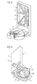
- the filter 7 in FIG. 3 is shown without filter fabric.
- the frame 12 is formed integrally with the housing 8.
- struts 18 are arranged, which run starting from the frame 12 in a star shape to each other.
- the struts 18 have different thicknesses.
- the opening 11 is arranged, so that the fuel flowing through the filter fabric passes through the opening 11, the channel 10 to the outlet 9 and thus to the fuel pump.
- FIG. 4 shows the housing 8 in a perspective view from below.
- the filter 7 is shown with filter fabric 15, which is welded on one side 13 of the frame 12.
- the channel 10 connects the opening in the frame with the outlet port 9.
- the housing 8 has in the region of the channel 10, based on the mounting position, a smaller extent in the vertical direction than the housing part 20 for the ejector 6. Since the housing part on the bottom of the Schwall pot 3 is seated, forms between the lower edge 23 and the Schwalltopfêt a gap. The lower edge 23 thereby surrounds an opening 24 through which additional fuel is sucked in by the fuel pump 4. In order to filter the fuel sucked through the opening 24, a filter fabric is welded on the edge 23, which is not shown for better representation of the channel 10.
- the housing part 20 surrounds the propulsion jet nozzle 25 of the suction jet pump 6, wherein the lower edge 26 of the housing part 20, the suction port 27 of the suction jet pump 6 limited.
- FIG. 5 shows the suction jet pump 6 with the filter 7 in the swirl pot 3 of the fuel delivery unit 2, wherein the fuel pump is not shown.
- the housing 8 integrally connects the suction jet pump 6 with the frame 12 of the filter 7.
- the housing part 20 of the nozzle 19 is formed, which merges into the propulsion jet nozzle 25.
- the mixing tube 21 connects to the propulsion jet nozzle 25.
- the propellant supplied via the nozzle 19 fuel is injected through the propulsion jet nozzle 25 into the mixing tube 21.
- the propulsion jet in the housing part 20 generates a negative pressure, whereby fuel is sucked from the fuel tank via the intake opening 27 and is conveyed via the mixing tube 21 into the swirl pot 3.
Landscapes
- Engineering & Computer Science (AREA)
- Chemical & Material Sciences (AREA)
- Combustion & Propulsion (AREA)
- Mechanical Engineering (AREA)
- General Engineering & Computer Science (AREA)
- Cooling, Air Intake And Gas Exhaust, And Fuel Tank Arrangements In Propulsion Units (AREA)
Applications Claiming Priority (2)
| Application Number | Priority Date | Filing Date | Title |
|---|---|---|---|
| DE102007040830 | 2007-08-29 | ||
| DE102007042110A DE102007042110A1 (de) | 2007-08-29 | 2007-09-05 | Kraftstofffördereinheit |
Publications (2)
| Publication Number | Publication Date |
|---|---|
| EP2031236A2 true EP2031236A2 (fr) | 2009-03-04 |
| EP2031236A3 EP2031236A3 (fr) | 2012-07-18 |
Family
ID=40032618
Family Applications (1)
| Application Number | Title | Priority Date | Filing Date |
|---|---|---|---|
| EP08105134A Withdrawn EP2031236A3 (fr) | 2007-08-29 | 2008-08-26 | Unité d'alimentation en carburant |
Country Status (1)
| Country | Link |
|---|---|
| EP (1) | EP2031236A3 (fr) |
Citations (1)
| Publication number | Priority date | Publication date | Assignee | Title |
|---|---|---|---|---|
| DE10138838A1 (de) | 2001-08-14 | 2003-03-06 | Siemens Ag | In einem Schwalltopf eines Kraftstoffbehälters eines Kraftfahrzeuges anzuordnende Fördereinheit |
Family Cites Families (3)
| Publication number | Priority date | Publication date | Assignee | Title |
|---|---|---|---|---|
| EP1103717B1 (fr) * | 1999-11-23 | 2005-03-23 | Siemens Aktiengesellschaft | Pompe disposée dans le réceptacle d'un réservoir de carburant d'un véhicule |
| US6951208B2 (en) * | 2003-10-22 | 2005-10-04 | Siemens Vdo Automotive Corporation | Fuel delivery system with flow re-director for improved re-priming sequence |
| JP4948775B2 (ja) * | 2004-06-14 | 2012-06-06 | 愛三工業株式会社 | 燃料供給装置 |
-
2008
- 2008-08-26 EP EP08105134A patent/EP2031236A3/fr not_active Withdrawn
Patent Citations (1)
| Publication number | Priority date | Publication date | Assignee | Title |
|---|---|---|---|---|
| DE10138838A1 (de) | 2001-08-14 | 2003-03-06 | Siemens Ag | In einem Schwalltopf eines Kraftstoffbehälters eines Kraftfahrzeuges anzuordnende Fördereinheit |
Also Published As
| Publication number | Publication date |
|---|---|
| EP2031236A3 (fr) | 2012-07-18 |
Similar Documents
| Publication | Publication Date | Title |
|---|---|---|
| DE69601413T2 (de) | Brennstoffzuführvorrichtung | |
| EP2399019B1 (fr) | Séparateur d'eau, en particulier pour systèmes d'alimentation en carburant de moteurs à combustion interne dans des véhicules à moteur | |
| EP0989936B1 (fr) | Dispositif de refoulement de carburant | |
| EP2102483B1 (fr) | Réservoir interne pour réservoir à carburant | |
| EP0806318A2 (fr) | Installation d'alimentation de carburant pour un véhicule automobile | |
| WO2007115925A1 (fr) | Pompe a jet aspirant | |
| EP1765625A1 (fr) | Dispositif destine a transporter du carburant d'un reservoir a un moteur a combustion interne | |
| EP2122152A1 (fr) | Unité d'acheminement | |
| DE10237050B3 (de) | Saugstrahlpumpe | |
| EP1210510B1 (fr) | Unite de refoulement | |
| DE102005029007A1 (de) | Tankeinbau-Kraftstoffversorgungseinheit mit montierbarer Strahlpumpeneinheit | |
| WO2008006833A1 (fr) | Unité d'alimentation pour l'alimentation en carburant | |
| DE10328206A1 (de) | Vorrichtung zum Fördern von Kraftstoff aus einem Vorratsbehälter zu einer Brennkraftmaschine | |
| DE3941892A1 (de) | Saugstrahlpumpe fuer den einsatz in einem kraftstofftank | |
| DE29922474U1 (de) | Kraftstoffversorgungseinrichtung für eine Brennkraftmaschine eines Kraftfahrzeugs | |
| EP2031236A2 (fr) | Unité d'alimentation en carburant | |
| DE102007042110A1 (de) | Kraftstofffördereinheit | |
| DE10322621B4 (de) | Zur Befestigung in einem Kraftstoffbehälter vorgesehene Fördereinheit | |
| DE3730567C2 (de) | Flüssigkeitspumpe | |
| EP1642019A1 (fr) | Dispositif pour acheminer du carburant contenu dans un reservoir a un moteur a combustion interne | |
| DE102010039547B4 (de) | Vorrichtung zum Fördern von Kraftstoff aus einem Vorratsbehälter zu einer Brennkraftmaschine | |
| EP1146224B1 (fr) | Dispositif d'alimentation en carburant d'un moteur à combustion interne | |
| WO2015172917A1 (fr) | Dispositif d'alimentation en carburant destiné à un véhicule automobile | |
| DE19915255B4 (de) | Fördereinrichtung für Kraftstoff | |
| DE102011084682A1 (de) | Kraftstoffförder-Vorrichtung mit geneigter Saugstrahlpumpe |
Legal Events
| Date | Code | Title | Description |
|---|---|---|---|
| PUAI | Public reference made under article 153(3) epc to a published international application that has entered the european phase |
Free format text: ORIGINAL CODE: 0009012 |
|
| AK | Designated contracting states |
Kind code of ref document: A2 Designated state(s): AT BE BG CH CY CZ DE DK EE ES FI FR GB GR HR HU IE IS IT LI LT LU LV MC MT NL NO PL PT RO SE SI SK TR |
|
| AX | Request for extension of the european patent |
Extension state: AL BA MK RS |
|
| PUAL | Search report despatched |
Free format text: ORIGINAL CODE: 0009013 |
|
| AK | Designated contracting states |
Kind code of ref document: A3 Designated state(s): AT BE BG CH CY CZ DE DK EE ES FI FR GB GR HR HU IE IS IT LI LT LU LV MC MT NL NO PL PT RO SE SI SK TR |
|
| AX | Request for extension of the european patent |
Extension state: AL BA MK RS |
|
| RIC1 | Information provided on ipc code assigned before grant |
Ipc: F02M 37/02 20060101ALI20120608BHEP Ipc: F02M 37/22 20060101ALI20120608BHEP Ipc: F02M 37/10 20060101AFI20120608BHEP |
|
| 17P | Request for examination filed |
Effective date: 20130118 |
|
| AKX | Designation fees paid |
Designated state(s): DE ES FR GB IT |
|
| 17Q | First examination report despatched |
Effective date: 20140219 |
|
| STAA | Information on the status of an ep patent application or granted ep patent |
Free format text: STATUS: THE APPLICATION IS DEEMED TO BE WITHDRAWN |
|
| 18D | Application deemed to be withdrawn |
Effective date: 20140304 |