EP2031468B1 - Montre pourvue d'un indicateur de fonctions - Google Patents
Montre pourvue d'un indicateur de fonctions Download PDFInfo
- Publication number
- EP2031468B1 EP2031468B1 EP07115258A EP07115258A EP2031468B1 EP 2031468 B1 EP2031468 B1 EP 2031468B1 EP 07115258 A EP07115258 A EP 07115258A EP 07115258 A EP07115258 A EP 07115258A EP 2031468 B1 EP2031468 B1 EP 2031468B1
- Authority
- EP
- European Patent Office
- Prior art keywords
- crown
- dial
- watch
- function indicator
- axial
- Prior art date
- Legal status (The legal status is an assumption and is not a legal conclusion. Google has not performed a legal analysis and makes no representation as to the accuracy of the status listed.)
- Active
Links
Images


Classifications
-
- G—PHYSICS
- G04—HOROLOGY
- G04B—MECHANICALLY-DRIVEN CLOCKS OR WATCHES; MECHANICAL PARTS OF CLOCKS OR WATCHES IN GENERAL; TIME PIECES USING THE POSITION OF THE SUN, MOON OR STARS
- G04B27/00—Mechanical devices for setting the time indicating means
- G04B27/02—Mechanical devices for setting the time indicating means by making use of the winding means
Definitions
- the present invention relates to a watch provided with a box that contains a watch movement, a dial and a function indicator associated with the dial, and a control ring disposed on the periphery of the box and having an axis of rotation. substantially parallel to the dial, said ring being slidable in its axial direction to be placed in axial positions corresponding to different functions in the watch, the function indicator being controlled by the axial displacements of the ring gear via a transmission mechanism.
- Such function indicators have already been provided, either so that the wearer of the watch does not err in function if the crown controls several, or to indicate that a crown called “screwed” is in its screwed position, that is to say a position which ensures a reinforced sealing of the watch case at the control rod, by compressing a seal under the crown.
- the first type mentioned above is illustrated in particular by the patent CH 534 381 according to which the control rod cooperates, in a first position, with a rotary selector which engages with a pinion of the rod one of the correction mechanisms that can be actuated by the rod put in its second position.
- the selector carries function symbols, which appear in turn in a window of the dial.
- This system has a complicated construction, making it difficult to mount and dismount the movement in the box. In addition, it always requires several manipulations to perform each function, because the selector must be returned to a neutral position after use.
- the patent EP 836 125 for an electronic alarm watch provides for the activation of the alarm by means of a rocker controlled by the axial displacement of the rod and fulfilling a dual role: an electric switch for the alarm function and an actuating lever a visual pointer on the dial.
- an electric switch for the alarm function and an actuating lever a visual pointer on the dial.
- Such an indicator obviously has only two positions.
- a function indicator associated especially with a crown screwed into the patent EP 730 758 . It is known that a screw-type crown is generally not fixed directly to the control rod, but to a sleeve surrounding the rod and cooperating with it by means of a coupling which allows axial play during screwing of the rod. crown, so as not to push the rod too far.
- the cited patent provides, on the inner end of this sleeve, a driving finger which, at the end of travel of the sleeve, rotates an interengaged gear in openings of a slider placed under the periphery of the dial.
- a driving finger which, at the end of travel of the sleeve, rotates an interengaged gear in openings of a slider placed under the periphery of the dial.
- One end of the slider appears in a window of the dial while screwing the crown ends.
- the interest of such an indicator is limited, since it can indicate only one function.
- a screwed crown of a mechanical watch has at least three positions (screwed, reassembly, time setting) and often a fourth for the correction of a calendar or other complication.
- the present invention aims at avoiding the disadvantages of the prior art, by providing a device capable of indicating the different functions corresponding to the different axial positions of the control ring, in particular at least three positions, with a very simple construction and a small footprint inside the watch box.
- the device must be feasible as an additional mechanism to a standard movement.
- An additional goal is that the device allows easy assembly and disassembly.
- the axial displacements of the crown are transmitted to the function indicator by a simple slide whose arrangement and movements are parallel to the movement control rod, therefore occupy much less space than lever mechanisms or gear of the prior art.
- the slider may be thin enough to be housed in a shallow groove, milled into the thickness of the watch movement platen, and thus extend to the desired location of the function indicator. .
- the wristwatch 1 represented in the figure 1 comprises, in a conventional manner, a sealed box 2 containing a clockwork movement, a time display by means of hands in front of a dial 4, and a display 5 of the date, in this case the date, in a window of the dial or in another way.
- the movement is mechanical in the present case, but it could as well be electromechanical with the same embodiment of the invention.
- the date display could also include an indication of the day of the week, month, etc. and could be electric in other cases.
- the movement is provided with a control rod 6 ( figure 2 ) rotating and sliding, which passes through the middle part 7 of the box 1 and carries at its outer end a ring 8 which, in this example, is screw-type crown.
- the screwed crown of a calendar watch can usually occupy four distinct axial positions: screwed, reassembled (or neutral if the movement is electromechanical), set date, set time.
- a mechanical visual indicator 10 which constantly indicates in which of these positions is the crown 8, therefore the respective functions that can fill the crown 8 when it is put in these positions.
- this indicator is disposed on the dial 4 in the vicinity of the crown 8, more precisely between the crown and the center of the dial.
- the indicator 10 comprises a needle 11 connected to the crown 8 by a mechanical transmission so as to pivot in front of a sectorial field 12 drawn on the dial 4.
- the field 12 is divided into four sectors which correspond to the four positions of the crown and carry symbols representing the functions for example: a colored dot O for the screwed position ensuring sealing, R for reassembly or neutral position, D for setting the date, H for setting the time.
- these symbols are arranged (from left to right in the drawing) in the same order as the corresponding positions of the crown.
- FIG. 2 there is recognized a known screwed crown construction, shown here in its screwed position.
- a tube 13 fixed in a hole of the middle part 7 is prominent outside the watch case and contains a rotating sleeve 15 which is welded inside the ring 8 and which can slide along the axis 14 of the tube and the crown.
- the sleeve 15 has a central channel 16 with a polygonal section, having an inner rim 17 at the front and in which a rod holder 18 can slide axially within certain limits, but remains connected in rotation to the sleeve and to the crown by means of a polygonal collar 19.
- the rod holder 18 is fixed by screwing at the end of the control rod 6 of the movement of the watch.
- the ring 8 contains an annular seal 20 and has an internal thread which is screwed on an external thread 22 of the tube 13 until the seal 20 is strongly compressed between the ring and the tube to ensure a high seal.
- another seal 23 provides the usual seal between the tube 13 and the sleeve 15.
- the rod 6 is of conventional construction, with a square section 25 carrying a sliding pinion 26 whose position is controlled in a known manner from a pull tab (not shown).
- This device may comprise notches which define the three axial positions of the rod 6.
- the mechanical transmission 30 connecting the ring 8 to the needle 11 of the function indicator 10 is visible in detail in FIG. figure 2 .
- a shaft 31 connects the needle 11 to a pinion 32 located behind the dial 4 and stopped in discrete positions by a jumper spring 33.
- the pinion 32 is meshed on a rack 34 formed on one side of the rear part of a slider plate 35, this portion 37 being guided in a groove 36 formed in the normal thickness of the plate of the movement. Near the end of the groove 36, the slide has a narrowed portion 38 and is continued by an arm 39 terminated by a lateral finger 40.
- a bevel is provided on the end of the sleeve 15 as well as that of the finger 40 to facilitate their assembly using the flexibility of the narrowed portion 38.
- a hole 43 in the finger allows to insert a tip to spread the finger 40 to disassemble the transmission 30 or the crown 8.
- the mechanical transmission 30, consisting essentially of flat parts 32 and 35 parallel to the platen of the movement, has a small thickness and can be accommodated largely in shallow recesses - called “counterbore” - platinum, being maintained by only one bridge. It is also not bulky in its plan, since the slider is narrow and it moves longitudinally inside its groove. It thus sweeps only a minimum of space while moving. Thus, it is possible to incorporate it in a standard caliber by modifying very little it.
- each axial displacement of the crown 8 rotates the pinion 32 and the needle 11 in proportion to the amplitude of the displacement, so that the four functional positions of the ring correspond to defined positions of the needle 11 in front of the four respective sectors O, R, D and H of indicator 10.
- the needle 11 is in front of the sector O and indicates that the sealing function of the crown is ensured.
- the spring 28 causes the crown and the sleeve 15 to move backwards until the rim 17 of the sleeve is stopped, as shown in FIG. figure 3 by the collar 19 of the rod holder 18 which has not moved axially.
- This position of the sleeve places the needle 11 in front of the sector R of the indicator 10, indicating that the crown is ready to be turned for reassembly of the movement.
- the explicit indication of the function that will be fulfilled by rotation of the crown in the current axial position facilitates the adjustment of the watch, because the user does not need to turn the crown to check if the stem was pulled from one notch or two. This avoids unintentionally changing the time or date, as commonly happens with a usual watch when the position of the crown is not the one we believe.
- the rotary elements 11, 31 and 32 could be deleted and the function indicator could be constituted by symbols such as O, R, D and H carried by the slider 35 and appearing in a window of the dial. 4.
- the indication by a needle better visualizes the progressive arrival in the screwed position.
- the sleeve 15 does not generally exist and the ring is attached to the end of the control rod.
- a groove equivalent to the groove 41 may be provided on the rod to receive the finger 40 of the slide of the device according to the invention. The indicated axial position will actually be that of the stem, but the construction of the transmission and indicator may remain unchanged.
Landscapes
- Physics & Mathematics (AREA)
- General Physics & Mathematics (AREA)
- Electromechanical Clocks (AREA)
- Electric Clocks (AREA)
Description
- La présente invention concerne une montre pourvue d'une boîte qui contient un mouvement d'horlogerie, un cadran et un indicateur de fonctions associé au cadran, et d'une couronne de commande disposée sur la périphérie de la boîte et ayant un axe de rotation sensiblement parallèle au cadran, ladite couronne étant coulissante dans sa direction axiale pour être mise dans des positions axiales correspondant à différentes fonctions dans la montre, l'indicateur de fonctions étant commandé par les déplacements axiaux de la couronne via un mécanisme de transmission.
- De tels indicateurs de fonctions ont déjà été prévus, soit pour que le porteur de la montre ne se trompe pas de fonction si la couronne en commande plusieurs, soit pour indiquer qu'une couronne dite « vissée » se trouve bien dans sa position vissée, c'est-à-dire une position qui assure une étanchéité renforcée de la boîte de montre au niveau de la tige de commande, par compression d'un joint sous la couronne.
- Le premier type susmentionné est illustré notamment par le brevet
CH 534 381 EP 836 125 - Une montre Richard Mille dénommée Calibre RM008, mentionnée sur le site web Worldtempus.com parmi les nouveautés 2004, comportait un indicateur de fonctions à trois positions correspondant aux positions de la couronne de commande, dont apparemment une position étanche. Toutefois aucune description de ce dispositif particulier n'est connue du demandeur. On trouve la description d'un indicateur de fonctions associé spécialement à une couronne vissée dans le brevet
EP 730 758 - En outre, il a été proposé des montres ayant un sélecteur pour choisir les fonctions à remplir par la couronne ou par un poussoir multifonctionnel, le sélecteur étant naturellement pourvu d'un indicateur de fonctions. Cela nécessite deux organes de commande distincts, pénétrant chacun dans la boîte de montre, ce qui n'est évidemment pas le cas de l'invention présentée ici.
- La présente invention vise à éviter les inconvénients de l'art antérieur, en fournissant un dispositif capable d'indiquer les différentes fonctions correspondant aux différentes positions axiales de la couronne de commande, en particulier au moins trois positions, avec une construction très simple et un faible encombrement à l'intérieur de la boîte de montre. Le dispositif doit être réalisable comme mécanisme additionnel à un mouvement standard. Un but supplémentaire est que le dispositif permette un montage et un démontage faciles.
- A cet effet, il est prévu une montre telle que définie dans la revendication 1.
- Grâce à ces caractéristiques, les déplacements axiaux de la couronne sont transmis à l'indicateur de fonctions par un simple coulisseau dont la disposition et les mouvements sont parallèles à la tige de commande du mouvement, donc occupent beaucoup moins de place que les mécanismes à leviers ou à engrenage de l'art antérieur. En outre, le coulisseau peut être assez mince pour être logé dans une rainure peu profonde, fraisée dans l'épaisseur de la platine du mouvement d'horlogerie, et s'étendre ainsi jusqu'à l'emplacement souhaité de l'indicateur de fonctions.
- D'autres caractéristiques et avantages de l'invention apparaîtront dans la description suivante d'un mode de réalisation particulier, présenté à titre d'exemple uniquement et illustré par les dessins annexés.
-
- La
figure 1 est une vue frontale schématique d'une montre-bracelet pourvue d'une couronne vissée et d'un indicateur de fonctions selon l'invention, - la
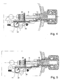
figure 2 est une vue en coupe partielle schématique de la couronne de commande de la montre de lafigure 1 en position vissée, montrant en outre le mécanisme de transmission qui relie cette couronne à l'indicateur de fonctions, et - les
figures 3 à 5 représentent trois autres positions dudit mécanisme pour trois positions axiales fonctionnelles de la couronne. - La montre-bracelet 1 représentée dans la
figure 1 comporte, de manière classique, une boîte étanche 2 contenant un mouvement d'horlogerie, un affichage de l'heure au moyen d'aiguilles devant un cadran 4, et un affichage 5 de la date, en l'occurrence le quantième, dans un guichet du cadran ou d'une autre manière. Le mouvement est mécanique dans le cas présent, mais il pourrait aussi bien être électromécanique avec le même mode de réalisation de l'invention. L'affichage de la date pourrait aussi comprendre une indication du jour de la semaine, du mois, etc. et pourrait être électrique dans d'autres cas. Comme d'habitude, le mouvement est pourvu d'une tige de commande 6 (figure 2 ) rotative et coulissante, qui traverse de manière étanche la carrure 7 de la boîte 1 et porte à son extrémité extérieure une couronne 8 qui, dans cet exemple, est du type couronne vissée. - Comme on l'a rappelé plus haut, la couronne vissée d'une montre à calendrier peut habituellement occuper quatre positions axiales distinctes : vissée, remontage (ou neutre si le mouvement est électromécanique), mise à la date, mise à l'heure. Avec la présente invention, il est prévu dans cette montre un indicateur visuel mécanique 10 qui indique constamment dans laquelle de ces positions se trouve la couronne 8, donc les fonctions respectives que peut remplir la couronne 8 quand elle est mise dans ces positions. Pour clarifier l'information qu'il donne, cet indicateur est disposé sur le cadran 4 au voisinage de la couronne 8, plus précisément entre la couronne et le centre du cadran. Dans le mode de réalisation représenté dans les dessins, l'indicateur 10 comporte une aiguille 11 reliée à la couronne 8 par une transmission mécanique de façon à pivoter devant un champ sectoriel 12 dessiné sur le cadran 4. Le champ 12 est divisé en quatre secteurs qui correspondent aux quatre positions de la couronne et portent des symboles représentant les fonctions correspondantes, par exemple : un point coloré O pour la position vissée assurant l'étanchéité, R pour le remontage ou la position neutre, D pour la mise à la date, H pour la mise à l'heure. Afin de faciliter les manoeuvres de la couronne par l'utilisateur, ces symboles sont rangés (de gauche à droite dans le dessin) dans le même ordre que les positions correspondantes de la couronne. Ainsi on voit bien que pour pouvoir corriger l'heure, il faut tirer la couronne 8 dans le sens de la flèche T jusqu'à la dernière position, correspondant à l'indication H.
- Dans la
figure 2 , on reconnaît une construction connue de couronne vissée, représentée ici dans sa position vissée. Un tube 13 fixé dans un trou de la carrure 7 est proéminent à l'extérieur de la boîte de montre et contient un manchon rotatif 15 qui est soudé à l'intérieur de la couronne 8 et qui peut coulisser suivant l'axe 14 du tube et de la couronne. Le manchon 15 possède un canal central 16 à section polygonale, ayant un rebord intérieur 17 à l'avant et dans lequel un porte-tige 18 peut coulisser axialement dans certaines limites, mais reste lié en rotation au manchon et à la couronne grâce à un collet polygonal 19. Le porte-tige 18 est fixé par vissage à l'extrémité de la tige de commande 6 du mouvement de la montre. La couronne 8 contient un joint annulaire d'étanchéité 20 et comporte un filetage interne qui se visse sur un filetage externe 22 du tube 13 jusqu'à ce que le joint 20 soit fortement comprimé entre la couronne et le tube pour garantir une étanchéité élevée. Lorsque la couronne est dévissée, un autre joint 23 assure l'étanchéité ordinaire entre le tube 13 et le manchon 15. - La tige 6 est de construction classique, avec un tronçon carré 25 portant un pignon coulant 26 dont la position est commandée de manière connue à partir d'une tirette (non représentée). Ce dispositif peut comporter des crans qui définissent les trois positions axiales de la tige 6. En comparant la
figure 2 et lafigure 3 , on peut voir que lorsqu'on visse la couronne 8 sur le tube 13, la tige 6 ne se déplace pas pendant que le manchon 15 avance, de sorte que le rebord intérieur 17 du manchon s'éloigne du collet 19 du porte-tige 18. Par contre, dans les autres positions de la couronne, selon lesfigures 3 à 5 , le collet 19 est maintenu en appui contre le rebord 17 par un ressort de compression 28, de sorte que la tige 6 suit les mouvements axiaux de la couronne 8 dans les deux sens, ainsi que les mouvements rotatifs. - La transmission mécanique 30 reliant la couronne 8 à l'aiguille 11 de l'indicateur de fonctions 10 est visible en détails dans la
figure 2 . Un arbre 31 relie l'aiguille 11 à un pignon 32 situé derrière le cadran 4 et arrêté dans des positions discrètes par un ressort sautoir 33. Le pignon 32 est engrené sur une crémaillère 34 ménagée sur un côté de la partie arrière d'un coulisseau plat 35, cette partie 37 étant guidée dans une rainure 36 ménagée dans l'épaisseur normale de la platine du mouvement. Près de l'extrémité de la rainure 36, le coulisseau présente une partie rétrécie 38 et se continue par un bras 39 terminé par un doigt latéral 40. Celui-ci est maintenu engagé dans une gorge annulaire 41 entourant l'extrémité proximale du manchon 15, sous l'effet d'un ressort 42, de sorte que le coulisseau 35 accompagne tous les mouvements axiaux du manchon 15 et de la couronne 8. Un biseau est ménagé aussi bien sur l'extrémité du manchon 15 que sur celle du doigt 40 afin de faciliter leur assemblage en utilisant la flexibilité de la partie rétrécie 38. Un trou 43 dans le doigt permet d'insérer une pointe pour écarter le doigt 40 afin de démonter la transmission 30 ou la couronne 8. - La transmission mécanique 30, formée essentiellement de pièces plates 32 et 35 parallèles à la platine du mouvement, présente une faible épaisseur et peut être logée en grande partie dans des évidements peu profonds - appelés « lamages » - de la platine, en étant maintenue par un seul pont. Elle est en outre peu encombrante dans son plan, étant donné que le coulisseau est étroit et qu'il se déplace longitudinalement à l'intérieur de sa rainure. Il ne balaie donc qu'un minimum d'espace en se déplaçant. Ainsi, il est possible de l'incorporer dans un calibre standard en modifiant très peu celui-ci.
- Avec la transmission 30, chaque déplacement axial de la couronne 8 fait tourner le pignon 32 et l'aiguille 11 proportionnellement à l'amplitude du déplacement, de sorte que les quatre positions fonctionnelles de la couronne correspondent à des positions définies de l'aiguille 11 devant les quatre secteurs respectifs O, R, D et H de l'indicateur 10.
- Dans la position vissée représentée en
figure 2 , l'aiguille 11 se trouve devant le secteur O et indique que la fonction d'étanchéité de la couronne est bien assurée. - Quand l'utilisateur dévisse la couronne 8 jusqu'à la dégager du filetage 22, le ressort 28 fait reculer la couronne et le manchon 15 jusqu'à ce que le rebord 17 du manchon soit arrêté, comme le montre la
figure 3 , par le collet 19 du porte-tige 18 qui n'a pas bougé axialement. Cette position du manchon place l'aiguille 11 devant le secteur R de l'indicateur 10, indiquant que la couronne est prête à être tournée pour le remontage du mouvement. - Si l'utilisateur tire alors la couronne 8 dans le sens de la flèche T jusqu'à la première position tirée de la tige 6, comme on le voit dans la
figure 4 , le déplacement axial du manchon 15 place l'aiguille 11 devant le secteur D de l'indicateur 10, indiquant que la couronne est prête à être tournée pour corriger l'indicateur de date 5. - Si l'utilisateur tire encore la couronne jusqu'à la seconde position tirée de la tige 6, comme le montre la
figure 5 , le déplacement axial du manchon 15 place l'aiguille 11 devant le secteur H de l'indicateur 10, indiquant que la couronne est prête à être tournée pour corriger l'heure affichée par les aiguilles. Lorsque la couronne 8 est repoussée en direction de la boîte 2, ce mouvement axial ramène l'aiguille 11 au secteur R, puis le vissage de la couronne amène progressivement l'aiguille sur le secteur O. - Lors de ces manoeuvres, l'indication explicite de la fonction qui va être remplie par rotation de la couronne dans la position axiale actuelle facilite le réglage de la montre, car l'utilisateur n'a pas besoin de tourner la couronne pour vérifier si la tige a été tirée d'un seul cran ou de deux. On évite ainsi de changer involontairement l'heure ou la date, comme cela arrive couramment avec une montre habituelle lorsque la position de la couronne n'est pas celle qu'on croit.
- Dans une variante non représentée, les éléments rotatifs 11, 31 et 32 pourraient être supprimés et l'indicateur de fonctions pourrait être constitué par des symboles tels que O, R, D et H portés par le coulisseau 35 et apparaissant dans un guichet du cadran 4. Toutefois l'indication par une aiguille visualise mieux l'arrivée progressive à la position vissée.
- Dans une montre ayant une couronne non vissée, le manchon 15 n'existe généralement pas et la couronne est fixée au bout de la tige de commande. Une gorge équivalente à la gorge 41 peut être ménagée sur la tige pour recevoir le doigt 40 du coulisseau du dispositif selon l'invention. La position axiale indiquée sera en fait celle de la tige, mais la construction de la transmission et de l'indicateur peut rester inchangée.
- La description qui précède et les dessins montrent que la présente invention permet de réaliser un indicateur de fonctions de la couronne d'une façon très simple et peu encombrante. Contrairement aux dispositifs à sélecteur mentionnés dans l'introduction, on conserve la tige de commande usuelle, ce qui simplifie beaucoup le mécanisme. En outre, la transmission à coulisseau parallèle à la tige permet d'indiquer un nombre quelconque de positions axiales et présente une grande facilité de montage et de démontage.
Claims (8)
- Montre pourvue d'une boîte qui contient un mouvement d'horlogerie, un cadran (4) et un indicateur de fonctions (10) associé au cadran, et d'une couronne de commande (8) disposée sur la périphérie de la boîte et ayant un axe de rotation (14) sensiblement parallèle au cadran, ladite couronne étant coulissante dans sa direction axiale pour être mise dans des positions axiales correspondant auxdites différentes fonctions, l'indicateur de fonctions étant agencé pour être commandé par des déplacements axiaux de la couronne via un mécanisme de transmission,
caractérisée en ce que ledit mécanisme de transmission (30) comporte un coulisseau (35) mobile parallèlement à l'axe (14) de la couronne (8) et ayant un doigt latéral (40) engagé dans une gorge annulaire (41) d'un élément (15) solidaire de la couronne. - Montre selon la revendication 1, caractérisée en ce que le coulisseau (35) comporte une partie flexible (38) disposée entre une partie arrière qui coulisse dans un moyen de guidage (36), et un bras avant (39) pourvu du doigt latéral (40).
- Montre selon la revendication 1 ou 2, caractérisée en ce que l'indicateur de fonctions (10) comporte un pignon (32) en prise avec une crémaillère (34) ménagée sur le coulisseau (35).
- Montre selon la revendication 3, caractérisée en ce que l'indicateur de fonctions comporte une aiguille (11), liée au dit pignon (32), et des symboles de fonctions (O, R, D, H) appliqués sur le cadran (4) en regard de ladite aiguille.
- Montre selon l'une des revendications précédentes, caractérisée en ce que l'indicateur de fonctions a au moins trois positions.
- Montre selon la revendication 5, caractérisée en ce que la couronne (8) est du type couronne vissée, ledit élément solidaire de la couronne étant un manchon (15) agencé pour pouvoir se déplacer axialement par rapport à la tige de commande (6) du mouvement lorsqu'on visse ou dévisse la couronne (8).
- Montre selon l'une des revendications précédentes, caractérisée en ce qu'elle comporte un affichage de date (5), qui peut être corrigé par rotation de la couronne (8) placée dans une position axiale de mise à la date, et en ce que l'indicateur de fonctions (10) comporte une indication spécifique (D) correspondant à cette position axiale de la couronne.
- Montre selon l'une des revendications précédentes, caractérisée en ce que l'indicateur de fonctions (10) est situé entre la couronne (8) et le centre du cadran (4).
Priority Applications (7)
| Application Number | Priority Date | Filing Date | Title |
|---|---|---|---|
| EP07115258A EP2031468B1 (fr) | 2007-08-30 | 2007-08-30 | Montre pourvue d'un indicateur de fonctions |
| AT07115258T ATE469380T1 (de) | 2007-08-30 | 2007-08-30 | Uhr, die mit einer funktionsanzeige ausgestattet ist |
| DE602007006799T DE602007006799D1 (de) | 2007-08-30 | 2007-08-30 | Uhr, die mit einer Funktionsanzeige ausgestattet ist |
| JP2008216207A JP5221247B2 (ja) | 2007-08-30 | 2008-08-26 | 機能表示装置付き時計 |
| US12/199,105 US7862226B2 (en) | 2007-08-30 | 2008-08-27 | Watch with a function indicator |
| CN2008101309623A CN101377651B (zh) | 2007-08-30 | 2008-08-29 | 带有功能指示器的手表 |
| HK09107918.5A HK1129931B (en) | 2007-08-30 | 2009-08-28 | Watch with a function indicator |
Applications Claiming Priority (1)
| Application Number | Priority Date | Filing Date | Title |
|---|---|---|---|
| EP07115258A EP2031468B1 (fr) | 2007-08-30 | 2007-08-30 | Montre pourvue d'un indicateur de fonctions |
Publications (2)
| Publication Number | Publication Date |
|---|---|
| EP2031468A1 EP2031468A1 (fr) | 2009-03-04 |
| EP2031468B1 true EP2031468B1 (fr) | 2010-05-26 |
Family
ID=39345176
Family Applications (1)
| Application Number | Title | Priority Date | Filing Date |
|---|---|---|---|
| EP07115258A Active EP2031468B1 (fr) | 2007-08-30 | 2007-08-30 | Montre pourvue d'un indicateur de fonctions |
Country Status (6)
| Country | Link |
|---|---|
| US (1) | US7862226B2 (fr) |
| EP (1) | EP2031468B1 (fr) |
| JP (1) | JP5221247B2 (fr) |
| CN (1) | CN101377651B (fr) |
| AT (1) | ATE469380T1 (fr) |
| DE (1) | DE602007006799D1 (fr) |
Families Citing this family (23)
| Publication number | Priority date | Publication date | Assignee | Title |
|---|---|---|---|---|
| ATE539388T1 (de) * | 2009-07-16 | 2012-01-15 | Rolex Sa | Uhr |
| FR2949265B1 (fr) * | 2009-08-19 | 2011-08-19 | G Et F Chatelain S A | Dispositif manuel de reglage et/ou de commande d'une fonction d'une piece d'horlogerie |
| US8439559B2 (en) * | 2010-03-23 | 2013-05-14 | Bright Aggregation Technology Limited | Timepiece with multi-functional actuator |
| US10335060B1 (en) | 2010-06-19 | 2019-07-02 | Dp Technologies, Inc. | Method and apparatus to provide monitoring |
| EP2453322B1 (fr) * | 2010-11-16 | 2013-07-17 | Omega SA | Correcteur rapide d'indicateur d'une grandeur temporelle pour pièce d'horlogerie |
| AU337152S (en) * | 2011-03-08 | 2011-06-15 | Omega Sa Omega Ag Omega Ltd | Watch |
| JP6003026B2 (ja) | 2011-08-30 | 2016-10-05 | カシオ計算機株式会社 | 文字板構造及び腕時計 |
| JP5927810B2 (ja) * | 2011-08-30 | 2016-06-01 | カシオ計算機株式会社 | 腕時計 |
| EP2592500B1 (fr) * | 2011-11-09 | 2019-01-16 | Rolex S.A. | Boîte de montre comportant une couronne à mémoire d'orientation |
| US9459597B2 (en) | 2012-03-06 | 2016-10-04 | DPTechnologies, Inc. | Method and apparatus to provide an improved sleep experience by selecting an optimal next sleep state for a user |
| EP2690510B1 (fr) * | 2012-07-24 | 2017-02-01 | ETA SA Manufacture Horlogère Suisse | Mécanisme d'affichage d'horlogerie |
| US9594354B1 (en) | 2013-04-19 | 2017-03-14 | Dp Technologies, Inc. | Smart watch extended system |
| US11963792B1 (en) | 2014-05-04 | 2024-04-23 | Dp Technologies, Inc. | Sleep ecosystem |
| US9448536B1 (en) * | 2015-03-04 | 2016-09-20 | Dp Technologies, Inc. | Self-winding mechanical watch with activity tracking |
| US11883188B1 (en) | 2015-03-16 | 2024-01-30 | Dp Technologies, Inc. | Sleep surface sensor based sleep analysis system |
| CN104698811B (zh) * | 2015-03-24 | 2017-04-26 | 惠州Tcl移动通信有限公司 | 表壳组件及手表 |
| EP3324250A1 (fr) * | 2016-11-16 | 2018-05-23 | The Swatch Group Research and Development Ltd | Dispositif indicateur de fuseaux horaires |
| CN110753884B (zh) * | 2017-04-18 | 2022-06-03 | 天美时集团美国股份有限公司 | 表冠推动器组件和包括该组件的手腕佩戴式电子设备 |
| US11382534B1 (en) | 2018-10-15 | 2022-07-12 | Dp Technologies, Inc. | Sleep detection and analysis system |
| CN110221530A (zh) * | 2019-07-19 | 2019-09-10 | 李冠康 | 一种手表 |
| EP3835886B1 (fr) * | 2019-12-10 | 2022-08-10 | The Swatch Group Research and Development Ltd | Montre pourvue d'un organe de commande |
| EP4024137B1 (fr) * | 2020-12-31 | 2023-08-23 | Meco S.A. | Dispositif de commande d'une pièce d'horlogerie |
| EP4546055A1 (fr) * | 2023-10-25 | 2025-04-30 | Omega SA | Dispositif d'embrayage d'un système de commande d'un mouvement horloger |
Family Cites Families (9)
| Publication number | Priority date | Publication date | Assignee | Title |
|---|---|---|---|---|
| CH289763A (fr) * | 1951-05-04 | 1953-03-31 | Wittnauer & Cie S A | Pièce d'horlogerie à calendrier. |
| CH185971A4 (fr) | 1971-02-08 | 1972-09-15 | ||
| JPS5137264A (fr) * | 1974-09-25 | 1976-03-29 | Citizen Watch Co Ltd | |
| CH645772GA3 (fr) * | 1981-09-23 | 1984-10-31 | ||
| US6490230B1 (en) * | 1991-04-16 | 2002-12-03 | Citizen Watch Co., Ltd. | Electronic watch with meter function and display means |
| CH686059B5 (de) * | 1994-09-22 | 1996-06-28 | Utc Service Ag | Armbanduhr mit Einschraubkrone. |
| JP2946198B2 (ja) | 1996-10-11 | 1999-09-06 | セイコーインスツルメンツ株式会社 | アラーム付き電子時計 |
| EP1586960A1 (fr) * | 2004-04-14 | 2005-10-19 | Meco S.A. | Couronne pour pièce d'horlogerie avec dispositif de débrayage |
| EP1939699B1 (fr) * | 2006-12-29 | 2012-05-30 | Montres Breguet S.A. | Dispositif correcteur coaxial multifonction |
-
2007
- 2007-08-30 DE DE602007006799T patent/DE602007006799D1/de active Active
- 2007-08-30 AT AT07115258T patent/ATE469380T1/de not_active IP Right Cessation
- 2007-08-30 EP EP07115258A patent/EP2031468B1/fr active Active
-
2008
- 2008-08-26 JP JP2008216207A patent/JP5221247B2/ja active Active
- 2008-08-27 US US12/199,105 patent/US7862226B2/en not_active Expired - Fee Related
- 2008-08-29 CN CN2008101309623A patent/CN101377651B/zh active Active
Also Published As
| Publication number | Publication date |
|---|---|
| JP5221247B2 (ja) | 2013-06-26 |
| DE602007006799D1 (de) | 2010-07-08 |
| HK1129931A1 (en) | 2009-12-11 |
| US20090059732A1 (en) | 2009-03-05 |
| JP2009058508A (ja) | 2009-03-19 |
| EP2031468A1 (fr) | 2009-03-04 |
| ATE469380T1 (de) | 2010-06-15 |
| US7862226B2 (en) | 2011-01-04 |
| CN101377651A (zh) | 2009-03-04 |
| CN101377651B (zh) | 2012-01-11 |
Similar Documents
| Publication | Publication Date | Title |
|---|---|---|
| EP2031468B1 (fr) | Montre pourvue d'un indicateur de fonctions | |
| EP2984526B1 (fr) | Mecanisme de selection et d'actionnement des fonctions d'un mouvement horloger | |
| EP1939699A1 (fr) | Dispositif correcteur coaxial multifonction | |
| EP2701015B1 (fr) | Dispositif de correction de fonctions affichées par une pièce d'horlogerie | |
| EP3602202B1 (fr) | Dispositif de réglage de fonctions d'une pièce d'horlogerie | |
| EP2008159B1 (fr) | Piece d'horlogerie comprenant un mecanisme a deux fuseaux horaires | |
| CH712219A2 (fr) | Mécanisme pour mouvement de montre à affichage rétrograde et sautant. | |
| CH702548B1 (fr) | Mécanisme de sélection de fonction pour mouvement d'horlogerie comportant au moins une complication. | |
| WO2011104480A1 (fr) | Couronne de remontoir de montre multifonctions | |
| EP3839657B1 (fr) | Mecanisme d'affichage d'horlogerie a la demande | |
| EP2687918B1 (fr) | Mécanisme de phase de lune | |
| EP2444861B1 (fr) | Sélecteur de fonction | |
| EP3485333B1 (fr) | Mécanisme de sélection et d'actionnement de fonctions d'un mouvement horloger | |
| EP2260355A1 (fr) | Piece d'horlogerie munie d'un cadran a index rotatif | |
| CH710118B1 (fr) | Pièce d'engrenage, mécanisme de réglage d'une différence horaire, mouvement horloger, et pièce d'horlogerie. | |
| EP3410228B1 (fr) | Mécanisme de commande déportée d'horlogerie | |
| EP2010972B1 (fr) | Piece d'horlogerie comportant un mecanisme de mise a l'heure commande par une lunette tournante | |
| EP3663866A1 (fr) | Piece d'horlogerie comportant un dispositif d'actionnement d'une couronne ou d'une soupape | |
| EP1271268B1 (fr) | Montre à double fuseau horaire | |
| EP2477080B1 (fr) | Pièce d'horlogerie à indication du fuseau horaire correspondant à une heure choisie | |
| EP2455823B1 (fr) | Pièce d'horlogerie à affichage de l'heure universelle | |
| EP1091269A1 (fr) | Boíte de montre | |
| EP2112566A1 (fr) | Dispositif indicateur analogique notamment pour pièce d'horlogerie | |
| CH715530A2 (fr) | Pièce d'horlogerie comportant un dispositif d'actionnement d'une couronne ou d'une soupape. | |
| CH720984B1 (fr) | Mécanisme de commande pour pièce d'horlogerie |
Legal Events
| Date | Code | Title | Description |
|---|---|---|---|
| PUAI | Public reference made under article 153(3) epc to a published international application that has entered the european phase |
Free format text: ORIGINAL CODE: 0009012 |
|
| AK | Designated contracting states |
Kind code of ref document: A1 Designated state(s): AT BE BG CH CY CZ DE DK EE ES FI FR GB GR HU IE IS IT LI LT LU LV MC MT NL PL PT RO SE SI SK TR |
|
| AX | Request for extension of the european patent |
Extension state: AL BA HR MK RS |
|
| 17P | Request for examination filed |
Effective date: 20090904 |
|
| AKX | Designation fees paid |
Designated state(s): AT BE BG CH CY CZ DE DK EE ES FI FR GB GR HU IE IS IT LI LT LU LV MC MT NL PL PT RO SE SI SK TR |
|
| GRAP | Despatch of communication of intention to grant a patent |
Free format text: ORIGINAL CODE: EPIDOSNIGR1 |
|
| GRAS | Grant fee paid |
Free format text: ORIGINAL CODE: EPIDOSNIGR3 |
|
| GRAA | (expected) grant |
Free format text: ORIGINAL CODE: 0009210 |
|
| AK | Designated contracting states |
Kind code of ref document: B1 Designated state(s): AT BE BG CH CY CZ DE DK EE ES FI FR GB GR HU IE IS IT LI LT LU LV MC MT NL PL PT RO SE SI SK TR |
|
| REG | Reference to a national code |
Ref country code: GB Ref legal event code: FG4D Free format text: NOT ENGLISH |
|
| REG | Reference to a national code |
Ref country code: CH Ref legal event code: EP |
|
| REG | Reference to a national code |
Ref country code: CH Ref legal event code: NV Representative=s name: ICB INGENIEURS CONSEILS EN BREVETS SA |
|
| REG | Reference to a national code |
Ref country code: IE Ref legal event code: FG4D Free format text: LANGUAGE OF EP DOCUMENT: FRENCH |
|
| REF | Corresponds to: |
Ref document number: 602007006799 Country of ref document: DE Date of ref document: 20100708 Kind code of ref document: P |
|
| REG | Reference to a national code |
Ref country code: NL Ref legal event code: VDEP Effective date: 20100526 |
|
| LTIE | Lt: invalidation of european patent or patent extension |
Effective date: 20100526 |
|
| PG25 | Lapsed in a contracting state [announced via postgrant information from national office to epo] |
Ref country code: SE Free format text: LAPSE BECAUSE OF FAILURE TO SUBMIT A TRANSLATION OF THE DESCRIPTION OR TO PAY THE FEE WITHIN THE PRESCRIBED TIME-LIMIT Effective date: 20100526 Ref country code: LT Free format text: LAPSE BECAUSE OF FAILURE TO SUBMIT A TRANSLATION OF THE DESCRIPTION OR TO PAY THE FEE WITHIN THE PRESCRIBED TIME-LIMIT Effective date: 20100526 |
|
| PG25 | Lapsed in a contracting state [announced via postgrant information from national office to epo] |
Ref country code: LV Free format text: LAPSE BECAUSE OF FAILURE TO SUBMIT A TRANSLATION OF THE DESCRIPTION OR TO PAY THE FEE WITHIN THE PRESCRIBED TIME-LIMIT Effective date: 20100526 Ref country code: AT Free format text: LAPSE BECAUSE OF FAILURE TO SUBMIT A TRANSLATION OF THE DESCRIPTION OR TO PAY THE FEE WITHIN THE PRESCRIBED TIME-LIMIT Effective date: 20100526 Ref country code: FI Free format text: LAPSE BECAUSE OF FAILURE TO SUBMIT A TRANSLATION OF THE DESCRIPTION OR TO PAY THE FEE WITHIN THE PRESCRIBED TIME-LIMIT Effective date: 20100526 Ref country code: IS Free format text: LAPSE BECAUSE OF FAILURE TO SUBMIT A TRANSLATION OF THE DESCRIPTION OR TO PAY THE FEE WITHIN THE PRESCRIBED TIME-LIMIT Effective date: 20100926 Ref country code: SI Free format text: LAPSE BECAUSE OF FAILURE TO SUBMIT A TRANSLATION OF THE DESCRIPTION OR TO PAY THE FEE WITHIN THE PRESCRIBED TIME-LIMIT Effective date: 20100526 |
|
| PG25 | Lapsed in a contracting state [announced via postgrant information from national office to epo] |
Ref country code: CY Free format text: LAPSE BECAUSE OF FAILURE TO SUBMIT A TRANSLATION OF THE DESCRIPTION OR TO PAY THE FEE WITHIN THE PRESCRIBED TIME-LIMIT Effective date: 20100609 Ref country code: PL Free format text: LAPSE BECAUSE OF FAILURE TO SUBMIT A TRANSLATION OF THE DESCRIPTION OR TO PAY THE FEE WITHIN THE PRESCRIBED TIME-LIMIT Effective date: 20100526 |
|
| REG | Reference to a national code |
Ref country code: IE Ref legal event code: FD4D |
|
| PG25 | Lapsed in a contracting state [announced via postgrant information from national office to epo] |
Ref country code: PT Free format text: LAPSE BECAUSE OF FAILURE TO SUBMIT A TRANSLATION OF THE DESCRIPTION OR TO PAY THE FEE WITHIN THE PRESCRIBED TIME-LIMIT Effective date: 20100927 Ref country code: DK Free format text: LAPSE BECAUSE OF FAILURE TO SUBMIT A TRANSLATION OF THE DESCRIPTION OR TO PAY THE FEE WITHIN THE PRESCRIBED TIME-LIMIT Effective date: 20100526 Ref country code: EE Free format text: LAPSE BECAUSE OF FAILURE TO SUBMIT A TRANSLATION OF THE DESCRIPTION OR TO PAY THE FEE WITHIN THE PRESCRIBED TIME-LIMIT Effective date: 20100526 Ref country code: IE Free format text: LAPSE BECAUSE OF FAILURE TO SUBMIT A TRANSLATION OF THE DESCRIPTION OR TO PAY THE FEE WITHIN THE PRESCRIBED TIME-LIMIT Effective date: 20100526 Ref country code: NL Free format text: LAPSE BECAUSE OF FAILURE TO SUBMIT A TRANSLATION OF THE DESCRIPTION OR TO PAY THE FEE WITHIN THE PRESCRIBED TIME-LIMIT Effective date: 20100526 |
|
| BERE | Be: lapsed |
Owner name: ETA SA MANUFACTURE HORLOGERE SUISSE Effective date: 20100831 |
|
| PG25 | Lapsed in a contracting state [announced via postgrant information from national office to epo] |
Ref country code: RO Free format text: LAPSE BECAUSE OF FAILURE TO SUBMIT A TRANSLATION OF THE DESCRIPTION OR TO PAY THE FEE WITHIN THE PRESCRIBED TIME-LIMIT Effective date: 20100526 Ref country code: SK Free format text: LAPSE BECAUSE OF FAILURE TO SUBMIT A TRANSLATION OF THE DESCRIPTION OR TO PAY THE FEE WITHIN THE PRESCRIBED TIME-LIMIT Effective date: 20100526 Ref country code: CZ Free format text: LAPSE BECAUSE OF FAILURE TO SUBMIT A TRANSLATION OF THE DESCRIPTION OR TO PAY THE FEE WITHIN THE PRESCRIBED TIME-LIMIT Effective date: 20100526 |
|
| PG25 | Lapsed in a contracting state [announced via postgrant information from national office to epo] |
Ref country code: MC Free format text: LAPSE BECAUSE OF NON-PAYMENT OF DUE FEES Effective date: 20100831 Ref country code: IT Free format text: LAPSE BECAUSE OF FAILURE TO SUBMIT A TRANSLATION OF THE DESCRIPTION OR TO PAY THE FEE WITHIN THE PRESCRIBED TIME-LIMIT Effective date: 20100526 |
|
| PLBE | No opposition filed within time limit |
Free format text: ORIGINAL CODE: 0009261 |
|
| STAA | Information on the status of an ep patent application or granted ep patent |
Free format text: STATUS: NO OPPOSITION FILED WITHIN TIME LIMIT |
|
| PG25 | Lapsed in a contracting state [announced via postgrant information from national office to epo] |
Ref country code: GR Free format text: LAPSE BECAUSE OF FAILURE TO SUBMIT A TRANSLATION OF THE DESCRIPTION OR TO PAY THE FEE WITHIN THE PRESCRIBED TIME-LIMIT Effective date: 20100827 |
|
| 26N | No opposition filed |
Effective date: 20110301 |
|
| REG | Reference to a national code |
Ref country code: DE Ref legal event code: R097 Ref document number: 602007006799 Country of ref document: DE Effective date: 20110228 |
|
| PG25 | Lapsed in a contracting state [announced via postgrant information from national office to epo] |
Ref country code: BE Free format text: LAPSE BECAUSE OF NON-PAYMENT OF DUE FEES Effective date: 20100831 |
|
| PG25 | Lapsed in a contracting state [announced via postgrant information from national office to epo] |
Ref country code: MT Free format text: LAPSE BECAUSE OF FAILURE TO SUBMIT A TRANSLATION OF THE DESCRIPTION OR TO PAY THE FEE WITHIN THE PRESCRIBED TIME-LIMIT Effective date: 20100526 |
|
| GBPC | Gb: european patent ceased through non-payment of renewal fee |
Effective date: 20110830 |
|
| PG25 | Lapsed in a contracting state [announced via postgrant information from national office to epo] |
Ref country code: GB Free format text: LAPSE BECAUSE OF NON-PAYMENT OF DUE FEES Effective date: 20110830 |
|
| PG25 | Lapsed in a contracting state [announced via postgrant information from national office to epo] |
Ref country code: BG Free format text: LAPSE BECAUSE OF FAILURE TO SUBMIT A TRANSLATION OF THE DESCRIPTION OR TO PAY THE FEE WITHIN THE PRESCRIBED TIME-LIMIT Effective date: 20100526 Ref country code: HU Free format text: LAPSE BECAUSE OF FAILURE TO SUBMIT A TRANSLATION OF THE DESCRIPTION OR TO PAY THE FEE WITHIN THE PRESCRIBED TIME-LIMIT Effective date: 20101127 Ref country code: LU Free format text: LAPSE BECAUSE OF NON-PAYMENT OF DUE FEES Effective date: 20100830 |
|
| PG25 | Lapsed in a contracting state [announced via postgrant information from national office to epo] |
Ref country code: TR Free format text: LAPSE BECAUSE OF FAILURE TO SUBMIT A TRANSLATION OF THE DESCRIPTION OR TO PAY THE FEE WITHIN THE PRESCRIBED TIME-LIMIT Effective date: 20100526 |
|
| PG25 | Lapsed in a contracting state [announced via postgrant information from national office to epo] |
Ref country code: BG Free format text: LAPSE BECAUSE OF FAILURE TO SUBMIT A TRANSLATION OF THE DESCRIPTION OR TO PAY THE FEE WITHIN THE PRESCRIBED TIME-LIMIT Effective date: 20100826 |
|
| PG25 | Lapsed in a contracting state [announced via postgrant information from national office to epo] |
Ref country code: ES Free format text: LAPSE BECAUSE OF FAILURE TO SUBMIT A TRANSLATION OF THE DESCRIPTION OR TO PAY THE FEE WITHIN THE PRESCRIBED TIME-LIMIT Effective date: 20100906 |
|
| REG | Reference to a national code |
Ref country code: FR Ref legal event code: PLFP Year of fee payment: 9 |
|
| REG | Reference to a national code |
Ref country code: FR Ref legal event code: PLFP Year of fee payment: 10 |
|
| REG | Reference to a national code |
Ref country code: FR Ref legal event code: PLFP Year of fee payment: 11 |
|
| REG | Reference to a national code |
Ref country code: FR Ref legal event code: PLFP Year of fee payment: 12 |
|
| P01 | Opt-out of the competence of the unified patent court (upc) registered |
Effective date: 20230701 |
|
| PGFP | Annual fee paid to national office [announced via postgrant information from national office to epo] |
Ref country code: DE Payment date: 20250724 Year of fee payment: 19 |
|
| PGFP | Annual fee paid to national office [announced via postgrant information from national office to epo] |
Ref country code: FR Payment date: 20250723 Year of fee payment: 19 |
|
| PGFP | Annual fee paid to national office [announced via postgrant information from national office to epo] |
Ref country code: CH Payment date: 20250901 Year of fee payment: 19 |