EP2031623B1 - Module transformateur de courant doté d'un câblage de changement de phase et interrupteur doté d'un tel module - Google Patents
Module transformateur de courant doté d'un câblage de changement de phase et interrupteur doté d'un tel module Download PDFInfo
- Publication number
- EP2031623B1 EP2031623B1 EP20070017243 EP07017243A EP2031623B1 EP 2031623 B1 EP2031623 B1 EP 2031623B1 EP 20070017243 EP20070017243 EP 20070017243 EP 07017243 A EP07017243 A EP 07017243A EP 2031623 B1 EP2031623 B1 EP 2031623B1
- Authority
- EP
- European Patent Office
- Prior art keywords
- phase
- switching device
- output
- contactor
- contactors
- Prior art date
- Legal status (The legal status is an assumption and is not a legal conclusion. Google has not performed a legal analysis and makes no representation as to the accuracy of the status listed.)
- Not-in-force
Links
Images


Classifications
-
- H—ELECTRICITY
- H01—ELECTRIC ELEMENTS
- H01H—ELECTRIC SWITCHES; RELAYS; SELECTORS; EMERGENCY PROTECTIVE DEVICES
- H01H51/00—Electromagnetic relays
- H01H51/005—Inversing contactors
-
- H—ELECTRICITY
- H01—ELECTRIC ELEMENTS
- H01H—ELECTRIC SWITCHES; RELAYS; SELECTORS; EMERGENCY PROTECTIVE DEVICES
- H01H71/00—Details of the protective switches or relays covered by groups H01H73/00 - H01H83/00
- H01H71/10—Operating or release mechanisms
- H01H71/12—Automatic release mechanisms with or without manual release
- H01H71/123—Automatic release mechanisms with or without manual release using a solid-state trip unit
- H01H71/125—Automatic release mechanisms with or without manual release using a solid-state trip unit characterised by sensing elements, e.g. current transformers
-
- H—ELECTRICITY
- H01—ELECTRIC ELEMENTS
- H01H—ELECTRIC SWITCHES; RELAYS; SELECTORS; EMERGENCY PROTECTIVE DEVICES
- H01H89/00—Combinations of two or more different basic types of electric switches, relays, selectors and emergency protective devices, not covered by any single one of the other main groups of this subclass
- H01H89/06—Combination of a manual reset circuit with a contactor, i.e. the same circuit controlled by both a protective and a remote control device
- H01H89/08—Combination of a manual reset circuit with a contactor, i.e. the same circuit controlled by both a protective and a remote control device with both devices using the same contact pair
Definitions
- the invention relates to a switching device according to claim 1.
- Known switching devices or EP 0 381 542 consist of two parallel arranged and interconnected contactors, which are connected in series with a line side connected circuit breaker.
- the interconnection between the contactors is preferably carried out with wiring blocks.
- the circuit breaker has an electronic overcurrent detection, which detects the signals of so-called N-releases.
- the N-releases are usually integrated in the circuit breaker.
- the circuit breaker on a biasing switch lock, which releases a circuit breaker plunger for opening the main circuit breaker contacts, in particular in a short circuit.
- the contactors each have a drive for operational switching. Depending on the desired direction of rotation of a connected consumer, in particular a connected electrical machine, either one contactor or the other contactor is turned on.
- the Protect current transformer for overcurrent detection to protect the downstream electric machine.
- the electric machine is preferably a three-phase electric motor.
- the object is to simplify the construction of a turning starter.
- a converter assembly for a switching device in particular for a reversing starter, is provided, which has two inputs with fixed contact pieces and an output for connecting an electrical load, in particular an electric machine.
- the two inputs are connected to the output via a phase-reversal wiring integrated in the converter module as well as via output-side phase conductors.
- the output side phase conductors are each passed through a current transformer.
- An advantage of the invention is that compared to the prior art only half of the current transformers is needed. In the three-phase case, only three instead of six current transformers are required. This reduces the size.
- Another advantage is the provision of fixed contact pieces of switching means to be mounted on the input side for operational switching and for safety shutdown.
- a separate switching point, as in the prior art, can advantageously be omitted.
- phase reversal wiring integrated in the transducer assembly allows for better cooling of the contacts.
- the converter module has a pin or socket strip connected to the current transformers. This eliminates the subsequent Verschaltungsaufwand for the current transformer.
- the pin or socket strip enables a compact and at the same time reliable connection for a higher-level monitoring electronics.
- the converter module is designed to be accommodated in a switching device, in particular in a reversing starter. This simplifies the assembly effort considerably.
- the transducer assembly is multi-phase, in particular three-phase executed.
- the two inputs are three-phase inputs and the output is a three-phase output.
- the contactors are formed in three phases.
- the phase-reversal wiring is designed according to the number of phases so that a change in direction of rotation, that is, a change in direction of the rotating field is accomplished.
- the object of the invention is achieved with a switching device according to claim 1, in particular with a reversing starter, which has a transducer assembly.
- the respective contactor outputs correspond to the stationary contact pieces of the converter module.
- the respective N-trigger act For safety shutdown directly on the main contacts of the two contactors.
- the particular advantage of the invention is the saving of a switching point.
- the fixed contact pieces of the converter module which are at the same time the electrical and terminalless inputs of the converter module, are used both for operational switching and for safety shutdown.
- Such a switching device has a drastically reduced size in comparison to the prior art.
- By already integrated phase reversal wiring mounting errors are advantageously avoided.
- the reduced number of contact points advantageously leads to a higher reliability of the switching device.
- the contactors each have a drive and a contactor tappet connected to the respective drive for actuating the respective main contacts.
- the N-releases release a preloaded N-trigger plunger to open the main contacts of both contactors.
- two mutually independent rams act together on the main contacts of the shooter in terms of a compact starter.
- the switching device is multi-phase, in particular three-phase, executed.
- the mains input is a three-phase mains input and the power supply network is a three-phase three-phase network, e.g. around a 400V three-phase network of a public utility.
- the network-side phase-reversal wiring is performed.
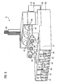
- FIG. 1 shows the circuit principle of a switching device 1 in the form of a turning starter 1 according to the prior art.
- FIG. 1 In the upper part of the FIG. 1 a circuit breaker 2 is shown, which is connected on the input side to a three-phase power supply network. In the lower part of the FIG. 1 are two parallel-connected contactors 41, 42 can be seen, which are both the input side and the output side, each with a phase reversal wiring 31, 32 are connected. At the bottom of the FIG. 1 is a three-phase output 71-73 for connecting a three-phase load, in particular an electric machine to see.
- FIG. 2 shows the associated circuit diagram of the reversing starter 1 according to FIG. 1 ,
- the three-phase mains input 11-13 for connection to the three-phase power supply network can be seen. It is ever a to the respective phase 11, 12, 13 connected in series N-trigger 21 for safety shutdown of the reversing starter 1 shown.
- the N-trigger 21 operated in the case of triggering, in particular in a Short circuit case, a circuit breaker plunger 22, which in turn acts on three-phase circuit breaker main contacts 23.
- the circuit breaker 2 thus disconnects the electrical machine from the power grid.
- three-phase refers to the power supply network used.
- the respective switching points each have three main contacts in the case of the absence of a neutral conductor.
- the respective switching points of the circuit breaker and the contactors can also be designed 4-pin. This means that the operational switching as well as the safety shutdown are then 4-pole.
- the two parallel-connected contactors 41, 42 can be seen, which on the input side 47 and output side 48 are connected to the input and output side phase reversing wiring 31, 32, that when switching a contactor 41 or the other contactor 42, a change of direction of the connected electrical Machine is effected.
- Both contactors 41, 42 have three current transformers 46 for detecting the respective phase current.
- a drive 43 of the contactors 41, 42 opens the respective main contacts 45.
- Reference numeral 44 denotes a contactor tappet.
- the three-phase output 71-73 can be seen.
- FIG. 3 shows the circuit principle of a turning starter 1 with a transducer assembly 6 according to the invention.
- the dashed upper box indicates a compact starter, which is designed for both operational switching and safety shutdown.
- the lower dashed box 6 shows the transducer assembly according to the invention.
- two contactors 41, 42 are shown as the output side and in the FIG. 3 Not shown fixed contact pieces of the contactors 41, 42 are also part of the transducer assembly 6.
- FIG. 4 shows the associated circuit diagram of the reversing starter 1 according to FIG. 3 , It has according to the invention, the transducer assembly 6, wherein the respective three-phase contactor outputs correspond to the fixed contact pieces 68 of the transducer assembly 6.
- the N-releases 21 release a preloaded N-trigger tappet 25 for opening the main contacts 45 of the two contactors 41, 42.
- the contactors 41, 42 each have a drive 43 and connected to the respective drive 43 contactor plunger 44 for actuating the respective main contacts 45.
- three current transformers 46 are shown for detecting a respective phase current.
- Reference symbol 67 denotes the output-side phase conductors of the converter module 6.
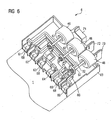
- FIG. 5 shows a perspective view of a transducer assembly 6 according to the invention in the left part of FIG. 5 are the two three-phase inputs 61-63; 64-66 watch with fixed contact pieces 68.
- the two three-phase inputs 61-63; 64-66 are connected via a built-in converter assembly 6 phase reversal wiring 32 and three output-side phase conductors 67 to the three-phase output 71-73.
- the phase reversal wiring 32 and the three-phase output 71-73 are in the present FIG. 5 only partially recognizable.
- the following FIG. 6 shows this in detail.
- the three output-side phase conductors 67 are each guided by a current transformer 46. They are exemplified as a solid bolt and connected by means of a screw 60 with the input-side phase reversal wiring 32.
- the current transformers 46 are designed as toroidal transducers or as a through-connection converter educated.
- the in the FIG. 5 unrecognizable current transformer windings and their electrical connections are connected to a pin header 69. Alternatively, a female connector can be used.
- the electrical signals of the current transformer 46 can be detected by a connected to the pin or female connector 69 monitoring electronics.
- the monitoring electronics is preferably integrated in the reversing starter 1 and designed as a printed circuit board.
- the reference numeral 81 denotes a first housing part. It serves to accommodate the current transformer 46, that is, the toroidal transformer shown. The leads of the toroidal core 46 are moved to the pin strip 69 shown and preferably soldered there. The first housing part 81 is then connected to a second housing part 82, that is inserted into this, snapped, screwed or locked. Subsequently, the output-side terminals 71-73 are pressed in the position shown and welded. In the lower part of the FIG. 5 is a third housing part 83 watch. In it, the prefabricated conductor of the output-side phase reversal wiring 32 are inserted or fitted. Subsequently, these are welded together and with the fixed contact pieces 68 of the electrical inputs 61-66. Thereafter, the second and third housing parts 82, 83 are mounted to each other.
- FIG. 6 shows a perspective view of the transducer assembly 6 according to FIG. 5 in the elevation.
- the components of the phase reversal wiring 32 are made of solid copper cables with a preferably quadrangular cross-section to permanently perform operating currents in the two-digit ampere range with low heat.
- the somewhat "airy,” that is, spaced arrangement of the components of the phase reversal wiring 32 allows effective dissipation of the heat dissipation power from the transducer assembly 6 to the outside.
- the illustrated converter assembly 6 or the reversing starter 1, in which the converter assembly 6 is accommodated, is designed for a continuous operating current of 32 A.
- the reversing starter 1 can also be used for larger operating currents, such. 64 A, or for smaller operating currents, e.g. 16 A, be designed.
Landscapes
- Physics & Mathematics (AREA)
- Electromagnetism (AREA)
- Engineering & Computer Science (AREA)
- Power Engineering (AREA)
- Breakers (AREA)
- Inverter Devices (AREA)
Claims (3)
- Dispositif commutateur (1), en particulier démarreur inverseur, pour inverser le sens de rotation d'un consommateur électrique connecté, en particulier d'une machine électrique, le dispositif commutateur étant configuré polyphasé et comprenant :- une entrée de réseau (11-13) destinée à être connectée à un réseau d'alimentation électrique,- un déclencheur N (21) connecté en série à la phase respective pour la déconnexion de sécurité du dispositif commutateur,- deux contacteurs (41, 42) dotés chacun d'une entrée de contacteur (51), de contacts principaux (45) et de pièces de contact fixes (68) comme sortie de contacteur,- un câblage inverseur de phase (31) côté réseau pour connecter l'entrée de réseau (11-13) aux entrées de contacteur (51) respectives,- un module transformateur (6) doté de deux entrées (61-63 ; 64-66) qui présentent les pièces de contact fixes (68) et d'une sortie (71-73) pour connecter la machine électrique,- les deux entrées (61-63 ; 64-66) étant connectées à la sortie (71-73) par le câblage inverseur de phase (32) intégré dans le module transformateur ainsi que par des conducteurs de phase (67) côté sortie, les conducteurs de phase (67) côté sortie traversant chacun un transformateur de courant (46),- et les sorties de contacteur respectives correspondant aux pièces de contact fixes (68) du module transformateur (6),- et les déclencheurs N (21) respectifs pour la déconnexion de sécurité agissant directement sur les contacts principaux (45) des deux contacteurs (41, 42).
- Dispositif commutateur selon la revendication 1, caractérisé en ce que les contacteurs (41, 42) sont dotés chacun d'un entraînement (43) et d'un poussoir de contacteur (44) relié à l'entraînement (43) respectif pour actionner les contacts principaux (45) respectifs, et en ce que dans le cas d'une déconnexion de sécurité les déclencheurs N (21) libèrent un poussoir précontraint (25) de déclencheur N pour ouvrir les contacts principaux (45) des deux contacteurs (41, 42).
- Dispositif commutateur selon la revendication 1 ou 2, caractérisé en ce que les transformateurs de courant (46) sont réalisés sous forme de transformateur toroïdal ou transformateur traversant, et un signal électrique généré par le transformateur de courant (46) est détecté par un système électronique de surveillance intégré dans le démarreur inverseur et réalisé sous forme de module plat.
Priority Applications (2)
| Application Number | Priority Date | Filing Date | Title |
|---|---|---|---|
| EP20070017243 EP2031623B1 (fr) | 2007-09-03 | 2007-09-03 | Module transformateur de courant doté d'un câblage de changement de phase et interrupteur doté d'un tel module |
| ES07017243T ES2436530T3 (es) | 2007-09-03 | 2007-09-03 | Módulo transformador de corriente con un cableado de inversión de fase, así como aparato de maniobra con un tal módulo transformador |
Applications Claiming Priority (1)
| Application Number | Priority Date | Filing Date | Title |
|---|---|---|---|
| EP20070017243 EP2031623B1 (fr) | 2007-09-03 | 2007-09-03 | Module transformateur de courant doté d'un câblage de changement de phase et interrupteur doté d'un tel module |
Publications (2)
| Publication Number | Publication Date |
|---|---|
| EP2031623A1 EP2031623A1 (fr) | 2009-03-04 |
| EP2031623B1 true EP2031623B1 (fr) | 2013-10-30 |
Family
ID=39926639
Family Applications (1)
| Application Number | Title | Priority Date | Filing Date |
|---|---|---|---|
| EP20070017243 Not-in-force EP2031623B1 (fr) | 2007-09-03 | 2007-09-03 | Module transformateur de courant doté d'un câblage de changement de phase et interrupteur doté d'un tel module |
Country Status (2)
| Country | Link |
|---|---|
| EP (1) | EP2031623B1 (fr) |
| ES (1) | ES2436530T3 (fr) |
Families Citing this family (4)
| Publication number | Priority date | Publication date | Assignee | Title |
|---|---|---|---|---|
| DE102008018261A1 (de) * | 2008-04-01 | 2009-10-15 | Siemens Aktiengesellschaft | Stromwandlerbaugruppe und elektromechanische Schaltvorrichtung |
| GB201514947D0 (en) * | 2015-08-21 | 2015-10-07 | Mc Power Innovations Ltd | Switch, distributor system and method of adjusting current imbalance or phase to neutral voltages |
| CN114783836B (zh) * | 2022-04-22 | 2023-12-26 | 福建鑫博亿电力科技有限公司 | 一种低压断路器的一二次回路分离方法 |
| CN118658710B (zh) * | 2024-07-15 | 2025-10-10 | 郑州市凯贝特互感器有限公司 | 一种电流互感器 |
Family Cites Families (5)
| Publication number | Priority date | Publication date | Assignee | Title |
|---|---|---|---|---|
| FR2642893B1 (fr) * | 1989-02-03 | 1991-04-19 | Telemecanique Electrique | Contacteur-inverseur protege utilisant un systeme de transmission multifonctionnel pour la commande d'interrupteurs de confirmation |
| EP0955660A1 (fr) * | 1998-05-08 | 1999-11-10 | Schurter AG | Disjoncteur électrique d'appareil avec une fonction de courant de surcharge et de manque de tension et un détecteur de courant de surcharge associé |
| US6140896A (en) * | 2000-03-10 | 2000-10-31 | Eaton Corporation | Electro-mechanical reversing contactor with a single, common base |
| DE102004017292A1 (de) * | 2004-04-05 | 2005-10-20 | Siemens Ag | Motorsteuergerät |
| WO2006049769A2 (fr) * | 2004-09-29 | 2006-05-11 | Gruner Klaus A | Relais de verrouillage electromagnetique multiphase et ensemble de moteur |
-
2007
- 2007-09-03 ES ES07017243T patent/ES2436530T3/es active Active
- 2007-09-03 EP EP20070017243 patent/EP2031623B1/fr not_active Not-in-force
Also Published As
| Publication number | Publication date |
|---|---|
| EP2031623A1 (fr) | 2009-03-04 |
| ES2436530T3 (es) | 2014-01-02 |
Similar Documents
| Publication | Publication Date | Title |
|---|---|---|
| EP2048679B1 (fr) | Agencement de sectionneur à coupure en charge | |
| EP2140471B1 (fr) | Élément de connexion pour la connexion de deux appareils de coupure | |
| EP1380042B1 (fr) | Unite de distribution, notamment demarreur de moteur, pour un consommateur | |
| EP0452250B1 (fr) | Dispositif de protection de courant de fuite | |
| DE19739780B4 (de) | Drehstrommotor | |
| EP1444761B1 (fr) | Systeme de barres collectrices polyphasees | |
| EP1529302B2 (fr) | Commutateur electrique | |
| EP2015341A1 (fr) | Module de protection de groupes pour une installation de commutateurs tout comme installation de commutateurs dotée d'un tel module de protection de groupes | |
| EP1917672B1 (fr) | Systeme de connexion comprenant un appareil de commutation electromagnetique, en particulier un contacteur electromagnetique, et un connecteur | |
| DE60213329T2 (de) | Leistungschalter mit gegossenem Gehäuse mit Anschlussklemme | |
| EP2031623B1 (fr) | Module transformateur de courant doté d'un câblage de changement de phase et interrupteur doté d'un tel module | |
| EP1593137A1 (fr) | Appareil d'installation et ensemble d'installation comprenant un appareil d'installation | |
| EP1362405B1 (fr) | Dispositif de reglage pour un moteur | |
| DE112018005842T5 (de) | Motorsteuerungssystem mit integriertem festkörperschütz und relais und verfahren zu dessen betrieb | |
| EP1203442B1 (fr) | Combinaison d'un contacteur-disjonteur et d'un demarreur pour demarrage en douceur | |
| WO2014161828A1 (fr) | Onduleur et module d'alimentation en courant continu pour onduleur | |
| WO2005020259A1 (fr) | Appareil de protection de commutation securise | |
| EP3726560A1 (fr) | Disjoncteur de protection compact | |
| DE102013214899A1 (de) | Leistungselektronikelement | |
| DE102019130977A1 (de) | Modulares motorsteuersystem auf leiterplattenebene mit integrierten schutz- und steuerkomponenten | |
| EP3703242B1 (fr) | Dispositif de commutation pour un consommateur électrique monophase ou multiphase | |
| EP1297547B1 (fr) | Barrette a connexions pour dispositifs et appareils electriques utilisables pour differents courants nominaux et comportant une cavite | |
| EP4322195B1 (fr) | Connecteur pour disjoncteur et contacteur de post-connexion, branchement comprenant un tel connecteur et ensemble comprenant un tel dérivation | |
| EP1570505B1 (fr) | Disjoncteur basse tension | |
| EP1630916A1 (fr) | Système d'alimentation pour interrupteur basse tension |
Legal Events
| Date | Code | Title | Description |
|---|---|---|---|
| PUAI | Public reference made under article 153(3) epc to a published international application that has entered the european phase |
Free format text: ORIGINAL CODE: 0009012 |
|
| AK | Designated contracting states |
Kind code of ref document: A1 Designated state(s): AT BE BG CH CY CZ DE DK EE ES FI FR GB GR HU IE IS IT LI LT LU LV MC MT NL PL PT RO SE SI SK TR |
|
| AX | Request for extension of the european patent |
Extension state: AL BA HR MK RS |
|
| 17P | Request for examination filed |
Effective date: 20090608 |
|
| 17Q | First examination report despatched |
Effective date: 20090730 |
|
| AKX | Designation fees paid |
Designated state(s): AT BE BG CH CY CZ DE DK EE ES FI FR GB GR HU IE IS IT LI LT LU LV MC MT NL PL PT RO SE SI SK TR |
|
| RAP1 | Party data changed (applicant data changed or rights of an application transferred) |
Owner name: SIEMENS AKTIENGESELLSCHAFT |
|
| GRAP | Despatch of communication of intention to grant a patent |
Free format text: ORIGINAL CODE: EPIDOSNIGR1 |
|
| INTG | Intention to grant announced |
Effective date: 20130514 |
|
| RIN1 | Information on inventor provided before grant (corrected) |
Inventor name: GOGEISSL, CHRISTIAN Inventor name: VOELZ, MATHIAS |
|
| GRAS | Grant fee paid |
Free format text: ORIGINAL CODE: EPIDOSNIGR3 |
|
| GRAA | (expected) grant |
Free format text: ORIGINAL CODE: 0009210 |
|
| AK | Designated contracting states |
Kind code of ref document: B1 Designated state(s): AT BE BG CH CY CZ DE DK EE ES FI FR GB GR HU IE IS IT LI LT LU LV MC MT NL PL PT RO SE SI SK TR |
|
| REG | Reference to a national code |
Ref country code: GB Ref legal event code: FG4D Free format text: NOT ENGLISH |
|
| REG | Reference to a national code |
Ref country code: CH Ref legal event code: EP |
|
| REG | Reference to a national code |
Ref country code: AT Ref legal event code: REF Ref document number: 638687 Country of ref document: AT Kind code of ref document: T Effective date: 20131115 |
|
| REG | Reference to a national code |
Ref country code: IE Ref legal event code: FG4D Free format text: LANGUAGE OF EP DOCUMENT: GERMAN |
|
| REG | Reference to a national code |
Ref country code: DE Ref legal event code: R096 Ref document number: 502007012433 Country of ref document: DE Effective date: 20131224 |
|
| REG | Reference to a national code |
Ref country code: ES Ref legal event code: FG2A Ref document number: 2436530 Country of ref document: ES Kind code of ref document: T3 Effective date: 20140102 |
|
| REG | Reference to a national code |
Ref country code: NL Ref legal event code: VDEP Effective date: 20131030 |
|
| REG | Reference to a national code |
Ref country code: LT Ref legal event code: MG4D |
|
| PG25 | Lapsed in a contracting state [announced via postgrant information from national office to epo] |
Ref country code: FI Free format text: LAPSE BECAUSE OF FAILURE TO SUBMIT A TRANSLATION OF THE DESCRIPTION OR TO PAY THE FEE WITHIN THE PRESCRIBED TIME-LIMIT Effective date: 20131030 Ref country code: IS Free format text: LAPSE BECAUSE OF FAILURE TO SUBMIT A TRANSLATION OF THE DESCRIPTION OR TO PAY THE FEE WITHIN THE PRESCRIBED TIME-LIMIT Effective date: 20140228 Ref country code: NL Free format text: LAPSE BECAUSE OF FAILURE TO SUBMIT A TRANSLATION OF THE DESCRIPTION OR TO PAY THE FEE WITHIN THE PRESCRIBED TIME-LIMIT Effective date: 20131030 Ref country code: SE Free format text: LAPSE BECAUSE OF FAILURE TO SUBMIT A TRANSLATION OF THE DESCRIPTION OR TO PAY THE FEE WITHIN THE PRESCRIBED TIME-LIMIT Effective date: 20131030 Ref country code: LT Free format text: LAPSE BECAUSE OF FAILURE TO SUBMIT A TRANSLATION OF THE DESCRIPTION OR TO PAY THE FEE WITHIN THE PRESCRIBED TIME-LIMIT Effective date: 20131030 |
|
| PG25 | Lapsed in a contracting state [announced via postgrant information from national office to epo] |
Ref country code: LV Free format text: LAPSE BECAUSE OF FAILURE TO SUBMIT A TRANSLATION OF THE DESCRIPTION OR TO PAY THE FEE WITHIN THE PRESCRIBED TIME-LIMIT Effective date: 20131030 Ref country code: CY Free format text: LAPSE BECAUSE OF FAILURE TO SUBMIT A TRANSLATION OF THE DESCRIPTION OR TO PAY THE FEE WITHIN THE PRESCRIBED TIME-LIMIT Effective date: 20131030 |
|
| PG25 | Lapsed in a contracting state [announced via postgrant information from national office to epo] |
Ref country code: PT Free format text: LAPSE BECAUSE OF FAILURE TO SUBMIT A TRANSLATION OF THE DESCRIPTION OR TO PAY THE FEE WITHIN THE PRESCRIBED TIME-LIMIT Effective date: 20140228 |
|
| PG25 | Lapsed in a contracting state [announced via postgrant information from national office to epo] |
Ref country code: EE Free format text: LAPSE BECAUSE OF FAILURE TO SUBMIT A TRANSLATION OF THE DESCRIPTION OR TO PAY THE FEE WITHIN THE PRESCRIBED TIME-LIMIT Effective date: 20131030 |
|
| REG | Reference to a national code |
Ref country code: DE Ref legal event code: R097 Ref document number: 502007012433 Country of ref document: DE |
|
| PG25 | Lapsed in a contracting state [announced via postgrant information from national office to epo] |
Ref country code: RO Free format text: LAPSE BECAUSE OF FAILURE TO SUBMIT A TRANSLATION OF THE DESCRIPTION OR TO PAY THE FEE WITHIN THE PRESCRIBED TIME-LIMIT Effective date: 20131030 Ref country code: PL Free format text: LAPSE BECAUSE OF FAILURE TO SUBMIT A TRANSLATION OF THE DESCRIPTION OR TO PAY THE FEE WITHIN THE PRESCRIBED TIME-LIMIT Effective date: 20131030 Ref country code: SK Free format text: LAPSE BECAUSE OF FAILURE TO SUBMIT A TRANSLATION OF THE DESCRIPTION OR TO PAY THE FEE WITHIN THE PRESCRIBED TIME-LIMIT Effective date: 20131030 Ref country code: CZ Free format text: LAPSE BECAUSE OF FAILURE TO SUBMIT A TRANSLATION OF THE DESCRIPTION OR TO PAY THE FEE WITHIN THE PRESCRIBED TIME-LIMIT Effective date: 20131030 |
|
| PLBE | No opposition filed within time limit |
Free format text: ORIGINAL CODE: 0009261 |
|
| STAA | Information on the status of an ep patent application or granted ep patent |
Free format text: STATUS: NO OPPOSITION FILED WITHIN TIME LIMIT |
|
| PG25 | Lapsed in a contracting state [announced via postgrant information from national office to epo] |
Ref country code: DK Free format text: LAPSE BECAUSE OF FAILURE TO SUBMIT A TRANSLATION OF THE DESCRIPTION OR TO PAY THE FEE WITHIN THE PRESCRIBED TIME-LIMIT Effective date: 20131030 |
|
| 26N | No opposition filed |
Effective date: 20140731 |
|
| REG | Reference to a national code |
Ref country code: DE Ref legal event code: R097 Ref document number: 502007012433 Country of ref document: DE Effective date: 20140731 |
|
| PG25 | Lapsed in a contracting state [announced via postgrant information from national office to epo] |
Ref country code: SI Free format text: LAPSE BECAUSE OF FAILURE TO SUBMIT A TRANSLATION OF THE DESCRIPTION OR TO PAY THE FEE WITHIN THE PRESCRIBED TIME-LIMIT Effective date: 20131030 |
|
| PG25 | Lapsed in a contracting state [announced via postgrant information from national office to epo] |
Ref country code: MC Free format text: LAPSE BECAUSE OF FAILURE TO SUBMIT A TRANSLATION OF THE DESCRIPTION OR TO PAY THE FEE WITHIN THE PRESCRIBED TIME-LIMIT Effective date: 20131030 Ref country code: LU Free format text: LAPSE BECAUSE OF FAILURE TO SUBMIT A TRANSLATION OF THE DESCRIPTION OR TO PAY THE FEE WITHIN THE PRESCRIBED TIME-LIMIT Effective date: 20140903 |
|
| REG | Reference to a national code |
Ref country code: CH Ref legal event code: PL |
|
| REG | Reference to a national code |
Ref country code: IE Ref legal event code: MM4A |
|
| REG | Reference to a national code |
Ref country code: FR Ref legal event code: ST Effective date: 20150529 |
|
| PG25 | Lapsed in a contracting state [announced via postgrant information from national office to epo] |
Ref country code: BE Free format text: LAPSE BECAUSE OF NON-PAYMENT OF DUE FEES Effective date: 20140930 |
|
| PG25 | Lapsed in a contracting state [announced via postgrant information from national office to epo] |
Ref country code: CH Free format text: LAPSE BECAUSE OF NON-PAYMENT OF DUE FEES Effective date: 20140930 Ref country code: LI Free format text: LAPSE BECAUSE OF NON-PAYMENT OF DUE FEES Effective date: 20140930 |
|
| PG25 | Lapsed in a contracting state [announced via postgrant information from national office to epo] |
Ref country code: IE Free format text: LAPSE BECAUSE OF NON-PAYMENT OF DUE FEES Effective date: 20140903 Ref country code: FR Free format text: LAPSE BECAUSE OF NON-PAYMENT OF DUE FEES Effective date: 20140930 |
|
| REG | Reference to a national code |
Ref country code: AT Ref legal event code: MM01 Ref document number: 638687 Country of ref document: AT Kind code of ref document: T Effective date: 20140903 |
|
| PG25 | Lapsed in a contracting state [announced via postgrant information from national office to epo] |
Ref country code: AT Free format text: LAPSE BECAUSE OF NON-PAYMENT OF DUE FEES Effective date: 20140903 |
|
| PG25 | Lapsed in a contracting state [announced via postgrant information from national office to epo] |
Ref country code: BG Free format text: LAPSE BECAUSE OF FAILURE TO SUBMIT A TRANSLATION OF THE DESCRIPTION OR TO PAY THE FEE WITHIN THE PRESCRIBED TIME-LIMIT Effective date: 20131030 |
|
| PG25 | Lapsed in a contracting state [announced via postgrant information from national office to epo] |
Ref country code: GR Free format text: LAPSE BECAUSE OF FAILURE TO SUBMIT A TRANSLATION OF THE DESCRIPTION OR TO PAY THE FEE WITHIN THE PRESCRIBED TIME-LIMIT Effective date: 20140131 Ref country code: MT Free format text: LAPSE BECAUSE OF FAILURE TO SUBMIT A TRANSLATION OF THE DESCRIPTION OR TO PAY THE FEE WITHIN THE PRESCRIBED TIME-LIMIT Effective date: 20131030 |
|
| PG25 | Lapsed in a contracting state [announced via postgrant information from national office to epo] |
Ref country code: HU Free format text: LAPSE BECAUSE OF FAILURE TO SUBMIT A TRANSLATION OF THE DESCRIPTION OR TO PAY THE FEE WITHIN THE PRESCRIBED TIME-LIMIT; INVALID AB INITIO Effective date: 20070903 Ref country code: TR Free format text: LAPSE BECAUSE OF FAILURE TO SUBMIT A TRANSLATION OF THE DESCRIPTION OR TO PAY THE FEE WITHIN THE PRESCRIBED TIME-LIMIT Effective date: 20131030 |
|
| P01 | Opt-out of the competence of the unified patent court (upc) registered |
Effective date: 20230510 |
|
| PGFP | Annual fee paid to national office [announced via postgrant information from national office to epo] |
Ref country code: IT Payment date: 20230920 Year of fee payment: 17 |
|
| PGFP | Annual fee paid to national office [announced via postgrant information from national office to epo] |
Ref country code: GB Payment date: 20231009 Year of fee payment: 17 |
|
| PGFP | Annual fee paid to national office [announced via postgrant information from national office to epo] |
Ref country code: ES Payment date: 20231227 Year of fee payment: 17 |
|
| PGFP | Annual fee paid to national office [announced via postgrant information from national office to epo] |
Ref country code: DE Payment date: 20231120 Year of fee payment: 17 |
|
| REG | Reference to a national code |
Ref country code: DE Ref legal event code: R119 Ref document number: 502007012433 Country of ref document: DE |
|
| GBPC | Gb: european patent ceased through non-payment of renewal fee |
Effective date: 20240903 |
|
| PG25 | Lapsed in a contracting state [announced via postgrant information from national office to epo] |
Ref country code: DE Free format text: LAPSE BECAUSE OF NON-PAYMENT OF DUE FEES Effective date: 20250401 |
|
| PG25 | Lapsed in a contracting state [announced via postgrant information from national office to epo] |
Ref country code: GB Free format text: LAPSE BECAUSE OF NON-PAYMENT OF DUE FEES Effective date: 20240903 |
|
| PG25 | Lapsed in a contracting state [announced via postgrant information from national office to epo] |
Ref country code: IT Free format text: LAPSE BECAUSE OF NON-PAYMENT OF DUE FEES Effective date: 20240903 |
|
| REG | Reference to a national code |
Ref country code: ES Ref legal event code: FD2A Effective date: 20251024 |
|
| PG25 | Lapsed in a contracting state [announced via postgrant information from national office to epo] |
Ref country code: ES Free format text: LAPSE BECAUSE OF NON-PAYMENT OF DUE FEES Effective date: 20240904 |