EP2031682A2 - Structures calibrées horizontalement pour des dispositifs électrochimiques et électroniques - Google Patents
Structures calibrées horizontalement pour des dispositifs électrochimiques et électroniques Download PDFInfo
- Publication number
- EP2031682A2 EP2031682A2 EP20080015279 EP08015279A EP2031682A2 EP 2031682 A2 EP2031682 A2 EP 2031682A2 EP 20080015279 EP20080015279 EP 20080015279 EP 08015279 A EP08015279 A EP 08015279A EP 2031682 A2 EP2031682 A2 EP 2031682A2
- Authority
- EP
- European Patent Office
- Prior art keywords
- layer
- layers
- vol
- multilayer structure
- graded
- Prior art date
- Legal status (The legal status is an assumption and is not a legal conclusion. Google has not performed a legal analysis and makes no representation as to the accuracy of the status listed.)
- Withdrawn
Links
- 239000000203 mixture Substances 0.000 claims abstract description 78
- 238000001218 confocal laser scanning microscopy Methods 0.000 claims description 94
- 229910001233 yttria-stabilized zirconia Inorganic materials 0.000 claims description 50
- 239000007787 solid Substances 0.000 claims description 28
- 239000000446 fuel Substances 0.000 claims description 27
- 238000004519 manufacturing process Methods 0.000 claims description 26
- 238000007650 screen-printing Methods 0.000 claims description 19
- 238000010345 tape casting Methods 0.000 claims description 17
- 239000011651 chromium Substances 0.000 claims description 16
- 238000000034 method Methods 0.000 claims description 16
- 238000003475 lamination Methods 0.000 claims description 12
- 241000968352 Scandia <hydrozoan> Species 0.000 claims description 8
- HJGMWXTVGKLUAQ-UHFFFAOYSA-N oxygen(2-);scandium(3+) Chemical compound [O-2].[O-2].[O-2].[Sc+3].[Sc+3] HJGMWXTVGKLUAQ-UHFFFAOYSA-N 0.000 claims description 8
- PNEYBMLMFCGWSK-UHFFFAOYSA-N aluminium oxide Inorganic materials [O-2].[O-2].[O-2].[Al+3].[Al+3] PNEYBMLMFCGWSK-UHFFFAOYSA-N 0.000 claims description 7
- 229910052593 corundum Inorganic materials 0.000 claims description 7
- 229910001845 yogo sapphire Inorganic materials 0.000 claims description 7
- 229910002449 CoO3−δ Inorganic materials 0.000 claims description 6
- 238000010030 laminating Methods 0.000 claims description 6
- 229910044991 metal oxide Inorganic materials 0.000 claims description 4
- 150000004706 metal oxides Chemical class 0.000 claims description 4
- SOEAEIPGNGLRLL-UHFFFAOYSA-N strontium chromium(3+) lanthanum(3+) oxygen(2-) Chemical compound [O--].[O--].[O--].[O--].[Cr+3].[Sr++].[La+3] SOEAEIPGNGLRLL-UHFFFAOYSA-N 0.000 claims 1
- 239000000725 suspension Substances 0.000 description 85
- 238000005245 sintering Methods 0.000 description 76
- VNWKTOKETHGBQD-UHFFFAOYSA-N methane Chemical compound C VNWKTOKETHGBQD-UHFFFAOYSA-N 0.000 description 56
- 239000012528 membrane Substances 0.000 description 36
- 239000000976 ink Substances 0.000 description 33
- 239000003054 catalyst Substances 0.000 description 32
- 230000000694 effects Effects 0.000 description 22
- 239000007789 gas Substances 0.000 description 22
- 239000000463 material Substances 0.000 description 22
- 239000002245 particle Substances 0.000 description 20
- 239000003345 natural gas Substances 0.000 description 19
- 229910021320 cobalt-lanthanum-strontium oxide Inorganic materials 0.000 description 17
- 239000003792 electrolyte Substances 0.000 description 16
- LFQSCWFLJHTTHZ-UHFFFAOYSA-N Ethanol Chemical compound CCO LFQSCWFLJHTTHZ-UHFFFAOYSA-N 0.000 description 14
- 238000006243 chemical reaction Methods 0.000 description 14
- 229920002037 poly(vinyl butyral) polymer Polymers 0.000 description 14
- 229920000036 polyvinylpyrrolidone Polymers 0.000 description 14
- 239000001267 polyvinylpyrrolidone Substances 0.000 description 14
- 235000013855 polyvinylpyrrolidone Nutrition 0.000 description 14
- MCMNRKCIXSYSNV-UHFFFAOYSA-N Zirconium dioxide Chemical compound O=[Zr]=O MCMNRKCIXSYSNV-UHFFFAOYSA-N 0.000 description 10
- 238000000151 deposition Methods 0.000 description 10
- 230000015572 biosynthetic process Effects 0.000 description 9
- 238000009826 distribution Methods 0.000 description 9
- 229910052759 nickel Inorganic materials 0.000 description 9
- 239000000843 powder Substances 0.000 description 9
- 229910052707 ruthenium Inorganic materials 0.000 description 9
- 239000000758 substrate Substances 0.000 description 9
- 239000011248 coating agent Substances 0.000 description 8
- 238000000576 coating method Methods 0.000 description 8
- 230000008021 deposition Effects 0.000 description 8
- 239000000654 additive Substances 0.000 description 7
- QVGXLLKOCUKJST-UHFFFAOYSA-N atomic oxygen Chemical compound [O] QVGXLLKOCUKJST-UHFFFAOYSA-N 0.000 description 7
- 238000000498 ball milling Methods 0.000 description 7
- 229910052760 oxygen Inorganic materials 0.000 description 7
- 239000001301 oxygen Substances 0.000 description 7
- 238000005507 spraying Methods 0.000 description 7
- 238000004544 sputter deposition Methods 0.000 description 7
- 230000007797 corrosion Effects 0.000 description 6
- 238000005260 corrosion Methods 0.000 description 6
- 238000007639 printing Methods 0.000 description 6
- 229920002799 BoPET Polymers 0.000 description 5
- 239000005041 Mylar™ Substances 0.000 description 5
- 239000010408 film Substances 0.000 description 5
- 238000002407 reforming Methods 0.000 description 5
- 239000002002 slurry Substances 0.000 description 5
- 238000001816 cooling Methods 0.000 description 4
- 239000011888 foil Substances 0.000 description 4
- 239000011253 protective coating Substances 0.000 description 4
- 229910003031 (La,Sr)CoO3 Inorganic materials 0.000 description 3
- CETPSERCERDGAM-UHFFFAOYSA-N ceric oxide Chemical compound O=[Ce]=O CETPSERCERDGAM-UHFFFAOYSA-N 0.000 description 3
- 229910000422 cerium(IV) oxide Inorganic materials 0.000 description 3
- 239000002001 electrolyte material Substances 0.000 description 3
- 238000011031 large-scale manufacturing process Methods 0.000 description 3
- -1 methane Chemical compound 0.000 description 3
- 239000000126 substance Substances 0.000 description 3
- 239000002699 waste material Substances 0.000 description 3
- OKTJSMMVPCPJKN-UHFFFAOYSA-N Carbon Chemical compound [C] OKTJSMMVPCPJKN-UHFFFAOYSA-N 0.000 description 2
- 239000004215 Carbon black (E152) Substances 0.000 description 2
- 229910000831 Steel Inorganic materials 0.000 description 2
- 229910052799 carbon Inorganic materials 0.000 description 2
- 239000000919 ceramic Substances 0.000 description 2
- 230000003247 decreasing effect Effects 0.000 description 2
- 239000007772 electrode material Substances 0.000 description 2
- 238000005868 electrolysis reaction Methods 0.000 description 2
- 229930195733 hydrocarbon Natural products 0.000 description 2
- 150000002430 hydrocarbons Chemical class 0.000 description 2
- 229910052739 hydrogen Inorganic materials 0.000 description 2
- 239000001257 hydrogen Substances 0.000 description 2
- 239000007788 liquid Substances 0.000 description 2
- 239000012466 permeate Substances 0.000 description 2
- 238000004080 punching Methods 0.000 description 2
- 238000000926 separation method Methods 0.000 description 2
- 238000000629 steam reforming Methods 0.000 description 2
- 239000010959 steel Substances 0.000 description 2
- 238000010290 vacuum plasma spraying Methods 0.000 description 2
- MYMOFIZGZYHOMD-UHFFFAOYSA-N Dioxygen Chemical compound O=O MYMOFIZGZYHOMD-UHFFFAOYSA-N 0.000 description 1
- UFHFLCQGNIYNRP-UHFFFAOYSA-N Hydrogen Chemical compound [H][H] UFHFLCQGNIYNRP-UHFFFAOYSA-N 0.000 description 1
- 229910019112 La0.2Sr0.8CoO3 Inorganic materials 0.000 description 1
- 229910002138 La0.6Sr0.4CoO3 Inorganic materials 0.000 description 1
- 229910002147 La0.6Sr0.4FeO3 Inorganic materials 0.000 description 1
- 229910002388 SrCoO2.5 Inorganic materials 0.000 description 1
- 230000009286 beneficial effect Effects 0.000 description 1
- 229910052797 bismuth Inorganic materials 0.000 description 1
- JCXGWMGPZLAOME-UHFFFAOYSA-N bismuth atom Chemical compound [Bi] JCXGWMGPZLAOME-UHFFFAOYSA-N 0.000 description 1
- 229910000416 bismuth oxide Inorganic materials 0.000 description 1
- 230000000903 blocking effect Effects 0.000 description 1
- 239000006227 byproduct Substances 0.000 description 1
- 239000010406 cathode material Substances 0.000 description 1
- ZQMUJDDOHHBPCP-UHFFFAOYSA-N chromium(3+) dioxido(oxo)manganese Chemical class [Cr+3].[Cr+3].[O-][Mn]([O-])=O.[O-][Mn]([O-])=O.[O-][Mn]([O-])=O ZQMUJDDOHHBPCP-UHFFFAOYSA-N 0.000 description 1
- 238000005336 cracking Methods 0.000 description 1
- 230000001627 detrimental effect Effects 0.000 description 1
- TYIXMATWDRGMPF-UHFFFAOYSA-N dibismuth;oxygen(2-) Chemical compound [O-2].[O-2].[O-2].[Bi+3].[Bi+3] TYIXMATWDRGMPF-UHFFFAOYSA-N 0.000 description 1
- 238000003618 dip coating Methods 0.000 description 1
- 238000001035 drying Methods 0.000 description 1
- 239000010411 electrocatalyst Substances 0.000 description 1
- 239000011532 electronic conductor Substances 0.000 description 1
- 238000005516 engineering process Methods 0.000 description 1
- 238000011156 evaluation Methods 0.000 description 1
- 238000001125 extrusion Methods 0.000 description 1
- 239000002737 fuel gas Substances 0.000 description 1
- 150000002431 hydrogen Chemical class 0.000 description 1
- 239000012535 impurity Substances 0.000 description 1
- 238000007641 inkjet printing Methods 0.000 description 1
- 230000007774 longterm Effects 0.000 description 1
- 229910002119 nickel–yttria stabilized zirconia Inorganic materials 0.000 description 1
- 229910052757 nitrogen Inorganic materials 0.000 description 1
- 230000003647 oxidation Effects 0.000 description 1
- 238000007254 oxidation reaction Methods 0.000 description 1
- AHKZTVQIVOEVFO-UHFFFAOYSA-N oxide(2-) Chemical compound [O-2] AHKZTVQIVOEVFO-UHFFFAOYSA-N 0.000 description 1
- SIWVEOZUMHYXCS-UHFFFAOYSA-N oxo(oxoyttriooxy)yttrium Chemical compound O=[Y]O[Y]=O SIWVEOZUMHYXCS-UHFFFAOYSA-N 0.000 description 1
- RVTZCBVAJQQJTK-UHFFFAOYSA-N oxygen(2-);zirconium(4+) Chemical compound [O-2].[O-2].[Zr+4] RVTZCBVAJQQJTK-UHFFFAOYSA-N 0.000 description 1
- 238000002360 preparation method Methods 0.000 description 1
- 230000001681 protective effect Effects 0.000 description 1
- 230000000171 quenching effect Effects 0.000 description 1
- 239000000565 sealant Substances 0.000 description 1
- 239000007921 spray Substances 0.000 description 1
- 230000035882 stress Effects 0.000 description 1
- 238000003786 synthesis reaction Methods 0.000 description 1
- 230000008646 thermal stress Effects 0.000 description 1
- 239000010409 thin film Substances 0.000 description 1
- 230000007704 transition Effects 0.000 description 1
- 238000011144 upstream manufacturing Methods 0.000 description 1
- XLYOFNOQVPJJNP-UHFFFAOYSA-N water Substances O XLYOFNOQVPJJNP-UHFFFAOYSA-N 0.000 description 1
- RUDFQVOCFDJEEF-UHFFFAOYSA-N yttrium(III) oxide Inorganic materials [O-2].[O-2].[O-2].[Y+3].[Y+3] RUDFQVOCFDJEEF-UHFFFAOYSA-N 0.000 description 1
- 229910001928 zirconium oxide Inorganic materials 0.000 description 1
- 229910000859 α-Fe Inorganic materials 0.000 description 1
Images




Classifications
-
- H—ELECTRICITY
- H01—ELECTRIC ELEMENTS
- H01M—PROCESSES OR MEANS, e.g. BATTERIES, FOR THE DIRECT CONVERSION OF CHEMICAL ENERGY INTO ELECTRICAL ENERGY
- H01M4/00—Electrodes
- H01M4/86—Inert electrodes with catalytic activity, e.g. for fuel cells
- H01M4/88—Processes of manufacture
- H01M4/8825—Methods for deposition of the catalytic active composition
- H01M4/8857—Casting, e.g. tape casting, vacuum slip casting
-
- H—ELECTRICITY
- H01—ELECTRIC ELEMENTS
- H01M—PROCESSES OR MEANS, e.g. BATTERIES, FOR THE DIRECT CONVERSION OF CHEMICAL ENERGY INTO ELECTRICAL ENERGY
- H01M8/00—Fuel cells; Manufacture thereof
- H01M8/02—Details
-
- C—CHEMISTRY; METALLURGY
- C23—COATING METALLIC MATERIAL; COATING MATERIAL WITH METALLIC MATERIAL; CHEMICAL SURFACE TREATMENT; DIFFUSION TREATMENT OF METALLIC MATERIAL; COATING BY VACUUM EVAPORATION, BY SPUTTERING, BY ION IMPLANTATION OR BY CHEMICAL VAPOUR DEPOSITION, IN GENERAL; INHIBITING CORROSION OF METALLIC MATERIAL OR INCRUSTATION IN GENERAL
- C23C—COATING METALLIC MATERIAL; COATING MATERIAL WITH METALLIC MATERIAL; SURFACE TREATMENT OF METALLIC MATERIAL BY DIFFUSION INTO THE SURFACE, BY CHEMICAL CONVERSION OR SUBSTITUTION; COATING BY VACUUM EVAPORATION, BY SPUTTERING, BY ION IMPLANTATION OR BY CHEMICAL VAPOUR DEPOSITION, IN GENERAL
- C23C28/00—Coating for obtaining at least two superposed coatings either by methods not provided for in a single one of groups C23C2/00 - C23C26/00 or by combinations of methods provided for in subclasses C23C and C25C or C25D
- C23C28/04—Coating for obtaining at least two superposed coatings either by methods not provided for in a single one of groups C23C2/00 - C23C26/00 or by combinations of methods provided for in subclasses C23C and C25C or C25D only coatings of inorganic non-metallic material
- C23C28/042—Coating for obtaining at least two superposed coatings either by methods not provided for in a single one of groups C23C2/00 - C23C26/00 or by combinations of methods provided for in subclasses C23C and C25C or C25D only coatings of inorganic non-metallic material including a refractory ceramic layer, e.g. refractory metal oxides, ZrO2, rare earth oxides
-
- C—CHEMISTRY; METALLURGY
- C23—COATING METALLIC MATERIAL; COATING MATERIAL WITH METALLIC MATERIAL; CHEMICAL SURFACE TREATMENT; DIFFUSION TREATMENT OF METALLIC MATERIAL; COATING BY VACUUM EVAPORATION, BY SPUTTERING, BY ION IMPLANTATION OR BY CHEMICAL VAPOUR DEPOSITION, IN GENERAL; INHIBITING CORROSION OF METALLIC MATERIAL OR INCRUSTATION IN GENERAL
- C23C—COATING METALLIC MATERIAL; COATING MATERIAL WITH METALLIC MATERIAL; SURFACE TREATMENT OF METALLIC MATERIAL BY DIFFUSION INTO THE SURFACE, BY CHEMICAL CONVERSION OR SUBSTITUTION; COATING BY VACUUM EVAPORATION, BY SPUTTERING, BY ION IMPLANTATION OR BY CHEMICAL VAPOUR DEPOSITION, IN GENERAL
- C23C28/00—Coating for obtaining at least two superposed coatings either by methods not provided for in a single one of groups C23C2/00 - C23C26/00 or by combinations of methods provided for in subclasses C23C and C25C or C25D
- C23C28/04—Coating for obtaining at least two superposed coatings either by methods not provided for in a single one of groups C23C2/00 - C23C26/00 or by combinations of methods provided for in subclasses C23C and C25C or C25D only coatings of inorganic non-metallic material
- C23C28/044—Coating for obtaining at least two superposed coatings either by methods not provided for in a single one of groups C23C2/00 - C23C26/00 or by combinations of methods provided for in subclasses C23C and C25C or C25D only coatings of inorganic non-metallic material coatings specially adapted for cutting tools or wear applications
-
- C—CHEMISTRY; METALLURGY
- C23—COATING METALLIC MATERIAL; COATING MATERIAL WITH METALLIC MATERIAL; CHEMICAL SURFACE TREATMENT; DIFFUSION TREATMENT OF METALLIC MATERIAL; COATING BY VACUUM EVAPORATION, BY SPUTTERING, BY ION IMPLANTATION OR BY CHEMICAL VAPOUR DEPOSITION, IN GENERAL; INHIBITING CORROSION OF METALLIC MATERIAL OR INCRUSTATION IN GENERAL
- C23C—COATING METALLIC MATERIAL; COATING MATERIAL WITH METALLIC MATERIAL; SURFACE TREATMENT OF METALLIC MATERIAL BY DIFFUSION INTO THE SURFACE, BY CHEMICAL CONVERSION OR SUBSTITUTION; COATING BY VACUUM EVAPORATION, BY SPUTTERING, BY ION IMPLANTATION OR BY CHEMICAL VAPOUR DEPOSITION, IN GENERAL
- C23C28/00—Coating for obtaining at least two superposed coatings either by methods not provided for in a single one of groups C23C2/00 - C23C26/00 or by combinations of methods provided for in subclasses C23C and C25C or C25D
- C23C28/04—Coating for obtaining at least two superposed coatings either by methods not provided for in a single one of groups C23C2/00 - C23C26/00 or by combinations of methods provided for in subclasses C23C and C25C or C25D only coatings of inorganic non-metallic material
- C23C28/048—Coating for obtaining at least two superposed coatings either by methods not provided for in a single one of groups C23C2/00 - C23C26/00 or by combinations of methods provided for in subclasses C23C and C25C or C25D only coatings of inorganic non-metallic material with layers graded in composition or physical properties
-
- H—ELECTRICITY
- H01—ELECTRIC ELEMENTS
- H01M—PROCESSES OR MEANS, e.g. BATTERIES, FOR THE DIRECT CONVERSION OF CHEMICAL ENERGY INTO ELECTRICAL ENERGY
- H01M4/00—Electrodes
- H01M4/86—Inert electrodes with catalytic activity, e.g. for fuel cells
- H01M4/8605—Porous electrodes
- H01M4/861—Porous electrodes with a gradient in the porosity
-
- H—ELECTRICITY
- H01—ELECTRIC ELEMENTS
- H01M—PROCESSES OR MEANS, e.g. BATTERIES, FOR THE DIRECT CONVERSION OF CHEMICAL ENERGY INTO ELECTRICAL ENERGY
- H01M4/00—Electrodes
- H01M4/86—Inert electrodes with catalytic activity, e.g. for fuel cells
- H01M4/8636—Inert electrodes with catalytic activity, e.g. for fuel cells with a gradient in another property than porosity
-
- H—ELECTRICITY
- H01—ELECTRIC ELEMENTS
- H01M—PROCESSES OR MEANS, e.g. BATTERIES, FOR THE DIRECT CONVERSION OF CHEMICAL ENERGY INTO ELECTRICAL ENERGY
- H01M4/00—Electrodes
- H01M4/86—Inert electrodes with catalytic activity, e.g. for fuel cells
- H01M4/8636—Inert electrodes with catalytic activity, e.g. for fuel cells with a gradient in another property than porosity
- H01M4/8642—Gradient in composition
-
- H—ELECTRICITY
- H01—ELECTRIC ELEMENTS
- H01M—PROCESSES OR MEANS, e.g. BATTERIES, FOR THE DIRECT CONVERSION OF CHEMICAL ENERGY INTO ELECTRICAL ENERGY
- H01M4/00—Electrodes
- H01M4/86—Inert electrodes with catalytic activity, e.g. for fuel cells
- H01M4/8647—Inert electrodes with catalytic activity, e.g. for fuel cells consisting of more than one material, e.g. consisting of composites
- H01M4/8657—Inert electrodes with catalytic activity, e.g. for fuel cells consisting of more than one material, e.g. consisting of composites layered
-
- H—ELECTRICITY
- H01—ELECTRIC ELEMENTS
- H01M—PROCESSES OR MEANS, e.g. BATTERIES, FOR THE DIRECT CONVERSION OF CHEMICAL ENERGY INTO ELECTRICAL ENERGY
- H01M4/00—Electrodes
- H01M4/86—Inert electrodes with catalytic activity, e.g. for fuel cells
- H01M4/88—Processes of manufacture
- H01M4/8825—Methods for deposition of the catalytic active composition
- H01M4/8828—Coating with slurry or ink
- H01M4/8835—Screen printing
-
- H—ELECTRICITY
- H01—ELECTRIC ELEMENTS
- H01M—PROCESSES OR MEANS, e.g. BATTERIES, FOR THE DIRECT CONVERSION OF CHEMICAL ENERGY INTO ELECTRICAL ENERGY
- H01M8/00—Fuel cells; Manufacture thereof
- H01M8/10—Fuel cells with solid electrolytes
- H01M8/12—Fuel cells with solid electrolytes operating at high temperature, e.g. with stabilised ZrO2 electrolyte
- H01M8/1213—Fuel cells with solid electrolytes operating at high temperature, e.g. with stabilised ZrO2 electrolyte characterised by the electrode/electrolyte combination or the supporting material
-
- H—ELECTRICITY
- H01—ELECTRIC ELEMENTS
- H01M—PROCESSES OR MEANS, e.g. BATTERIES, FOR THE DIRECT CONVERSION OF CHEMICAL ENERGY INTO ELECTRICAL ENERGY
- H01M8/00—Fuel cells; Manufacture thereof
- H01M8/10—Fuel cells with solid electrolytes
- H01M8/12—Fuel cells with solid electrolytes operating at high temperature, e.g. with stabilised ZrO2 electrolyte
- H01M8/124—Fuel cells with solid electrolytes operating at high temperature, e.g. with stabilised ZrO2 electrolyte characterised by the process of manufacturing or by the material of the electrolyte
-
- H—ELECTRICITY
- H01—ELECTRIC ELEMENTS
- H01M—PROCESSES OR MEANS, e.g. BATTERIES, FOR THE DIRECT CONVERSION OF CHEMICAL ENERGY INTO ELECTRICAL ENERGY
- H01M4/00—Electrodes
- H01M4/86—Inert electrodes with catalytic activity, e.g. for fuel cells
- H01M2004/8678—Inert electrodes with catalytic activity, e.g. for fuel cells characterised by the polarity
- H01M2004/8684—Negative electrodes
-
- H—ELECTRICITY
- H01—ELECTRIC ELEMENTS
- H01M—PROCESSES OR MEANS, e.g. BATTERIES, FOR THE DIRECT CONVERSION OF CHEMICAL ENERGY INTO ELECTRICAL ENERGY
- H01M8/00—Fuel cells; Manufacture thereof
- H01M8/10—Fuel cells with solid electrolytes
- H01M8/12—Fuel cells with solid electrolytes operating at high temperature, e.g. with stabilised ZrO2 electrolyte
- H01M2008/1293—Fuel cells with solid oxide electrolytes
-
- H—ELECTRICITY
- H01—ELECTRIC ELEMENTS
- H01M—PROCESSES OR MEANS, e.g. BATTERIES, FOR THE DIRECT CONVERSION OF CHEMICAL ENERGY INTO ELECTRICAL ENERGY
- H01M2300/00—Electrolytes
- H01M2300/0088—Composites
- H01M2300/0094—Composites in the form of layered products, e.g. coatings
-
- Y—GENERAL TAGGING OF NEW TECHNOLOGICAL DEVELOPMENTS; GENERAL TAGGING OF CROSS-SECTIONAL TECHNOLOGIES SPANNING OVER SEVERAL SECTIONS OF THE IPC; TECHNICAL SUBJECTS COVERED BY FORMER USPC CROSS-REFERENCE ART COLLECTIONS [XRACs] AND DIGESTS
- Y02—TECHNOLOGIES OR APPLICATIONS FOR MITIGATION OR ADAPTATION AGAINST CLIMATE CHANGE
- Y02E—REDUCTION OF GREENHOUSE GAS [GHG] EMISSIONS, RELATED TO ENERGY GENERATION, TRANSMISSION OR DISTRIBUTION
- Y02E60/00—Enabling technologies; Technologies with a potential or indirect contribution to GHG emissions mitigation
- Y02E60/30—Hydrogen technology
- Y02E60/50—Fuel cells
-
- Y—GENERAL TAGGING OF NEW TECHNOLOGICAL DEVELOPMENTS; GENERAL TAGGING OF CROSS-SECTIONAL TECHNOLOGIES SPANNING OVER SEVERAL SECTIONS OF THE IPC; TECHNICAL SUBJECTS COVERED BY FORMER USPC CROSS-REFERENCE ART COLLECTIONS [XRACs] AND DIGESTS
- Y02—TECHNOLOGIES OR APPLICATIONS FOR MITIGATION OR ADAPTATION AGAINST CLIMATE CHANGE
- Y02P—CLIMATE CHANGE MITIGATION TECHNOLOGIES IN THE PRODUCTION OR PROCESSING OF GOODS
- Y02P70/00—Climate change mitigation technologies in the production process for final industrial or consumer products
- Y02P70/50—Manufacturing or production processes characterised by the final manufactured product
-
- Y—GENERAL TAGGING OF NEW TECHNOLOGICAL DEVELOPMENTS; GENERAL TAGGING OF CROSS-SECTIONAL TECHNOLOGIES SPANNING OVER SEVERAL SECTIONS OF THE IPC; TECHNICAL SUBJECTS COVERED BY FORMER USPC CROSS-REFERENCE ART COLLECTIONS [XRACs] AND DIGESTS
- Y10—TECHNICAL SUBJECTS COVERED BY FORMER USPC
- Y10T—TECHNICAL SUBJECTS COVERED BY FORMER US CLASSIFICATION
- Y10T156/00—Adhesive bonding and miscellaneous chemical manufacture
- Y10T156/10—Methods of surface bonding and/or assembly therefor
- Y10T156/1089—Methods of surface bonding and/or assembly therefor of discrete laminae to single face of additional lamina
Definitions
- the present invention relates to a horizontally graded multilayer structure suitable for use as an electrode in electrochemical devices and to a method for producing same.
- Other applications of the graded multilayer structure include protective coatings for corrosion or mechanical wear.
- the formation of carbon will result in a fast blocking of the active sites in the anode structure. This may be prevented by using, e.g. an all-ceramic anode for direct conversion of natural gas to CO, CO 2 and water at the inlet which further down the stream may be replaced by Ni-containing electrode for a more efficient conversion. Carbon formation may also be prevented by a slower conversion at the inlet.
- EP-A-1701402 relates to systems and methods for minimizing temperature differences and gradients in solid oxide fuel cells.
- a manifold heat exchanger is used, which reduces thermal stress and increases cell life. Air passes from a periphery of a cell towards the cell centre, absorbs the heat, and proceeds to the manifold heat exchanger adjacent to the cell, where it absorbs further heat. Fuel is directed counter current to the air, which keeps hot spots away from the cell stack seals and directs hot air towards intense reforming areas on the cell to mitigate quenching effects of internal reforming.
- US patent 6,228,521 concerns a high power density solid oxide fuel cell having a cathode, electrolyte and graded porous anode.
- the anode is formed from NiO and zirconium oxide doped with yttrium oxide and exhibits a graded density which allows thicker and thus stronger anodes without sacrificing electrochemical performance.
- US patent 4,329,403 relates to an electrolyte-electrode assembly for high temperature fuel cells in which the electrolyte member is adapted to exhibit a more gradual transition in coefficient of thermal expansion in going from the anode electrode to the inner electrolyte region and in going from the cathode electrode to the inner electrolyte region.
- US patent 5,171,645 discloses a graded metal oxide electrolyte comprising gradiations of zirconia and bismuth oxide across the cross-section of the electrolyte.
- the gradiation of the compositional content across the wall thickness of the electrolyte from a substantially pure zirconia surface zone to a substantially pure bismuth oxide-yttria surface zone minimizes the stress at the interfaces between the various compositional zones.
- US-A1-2005/0092597 relates to a method of forming a thin-film fuel cell electrode, comprising the provision of a substrate and at least one deposition device; developing a deposition characteristic profile having at least one porous layer based on predetermined desired electrode properties; and forming a film in accordance with said deposition material from said deposition device while varying a relative position of said substrate in relation to said deposition device with respect to at least a first axis.
- sputter guns are used as the deposition device.
- said sputter guns result in varying thickness as the overlapping areas are thicker than the surrounding areas, which leads to unwanted variations of the layer properties in a horizontal direction.
- sputtering only thin layers well below 1 ⁇ m can be provided, which is too thin for applications in solid oxide cells as employed today, where well performing electrodes typically has electrochemical activity in thicknesses of 10 - 15 microns.
- sputtering is a very slow and expensive process and thus is very cost intensive, prohibiting large scale production. Further to that it is difficult to achieve porous layers and there is also a significant waste material when sputtering methods are used (preparation of targets and material deposited outside of the substrate).
- EP-A-1441406 discloses a method for making a fuel cell anode, comprising the steps of:
- US-A-2004/0086633 discloses a method for the fabrication and evaluation of electrode and electrolyte materials for use in solid oxide fuel cells, the method comprising:
- graded multilayer structures having a suitable thickness of ca. 10 microns or more, which may be used as anodes in solid oxide fuel cells, which have a sufficient horizontal grading without the layer having any significant thickness variations, having an improved life time, and which can be produced in a cost efficient way without much waste material in view of the desires and requirements for industrial large scale production.
- a graded multilayer structure comprising a support layer (1) and at least 10 layers (2, 3) forming a graded layer, wherein each of the at least 10 layers (2, 3) is at least partially in contact with the support layer (1), wherein the at least 10 layers (2, 3) differ from each other in at least one property selected from layer composition, porosity and conductivity, and wherein the at least 10 layers (2, 3) are arranged such that the layer composition, porosity and/or conductivity horizontally to the support layer (1) forms a gradient over the total layer area.
- a graded multilayer structure comprising a support layer (1) and at least two layers (2, 3) forming a graded layer, wherein each of the at least two layers (2, 3) is at least partially in contact with the support layer (1), wherein the at least two layers (2, 3) differ from each other in at least one property selected from layer composition, porosity and conductivity, wherein the at least two layers (2, 3) are arranged such that the layer composition, porosity and/or conductivity horizontally to the support layer (1) forms a gradient over the total layer area, and wherein the overall thickness of the graded layer comprising the at least two layers (2, 3) is more than 5 ⁇ m.
- the object is further achieved by a method for producing the above graded multilayer structure, comprising the steps of:
- the present invention relates to a graded multilayer structure, comprising a support layer (1) and at least 10 layers (2, 3) forming a graded layer, wherein each of the at least 10 layers (2, 3) is at least partially in contact with the support layer (1), wherein the at least 10 layers (2, 3) differ from each other in at least one property selected from layer composition, porosity and conductivity, and wherein the at least 10 layers (2, 3) are arranged such that the layer composition, porosity and/or conductivity horizontally to the support layer (1) forms a gradient over the total layer area.
- grading patterns are given in Figure 1 , including a gradient along the edges, diagonal or circular gradients; only a part of all layers is shown for better illustration of the principle.
- Such structures are suitable for use especially as electrodes in electrochemical devices where differences in performance or properties across a layer are advantageous. This is particularly the case for solid oxide cells (SOC) and membrane cells for oxygen or hydrogen separation, where an accurate control of the local electrochemical activity enhances the overall efficiency and durability.
- SOC solid oxide cells
- membrane cells for oxygen or hydrogen separation
- Other applications include protective coatings for corrosion or mechanical wear.
- the gradient may apply to all properties of the layer in question, and may for instance comprise one or more of the following properties: composition, porosity, impurity level, conductivity, density, abrasiveness, mechanical strength, materials cost etc.
- the graded layer comprises at least 10 layers.
- the general principle is illustrated in Figure 2 wherein the graded multilayer structure comprises seven illustrated layers forming a horizontal grading. Layer 1 has property 1 and layer 7 has property 2.
- the layers in between can be fine tuned to change linearly or by any other gradient from property 1 to property 2 between layer 1 and layer 7.
- the layers next to each other are depicted as overlapping layers. This is however not necessary, as illustrated in Figure 3 , where the layers are adjacent to each other.
- the grading does not necessarily have to change from one limit to the other going from edge to edge, but may undergo local maxima and/or minima instead.
- the present invention provides a graded multilayer structure, comprising a support layer (1) and at least two layers (2, 3) forming a graded layer, wherein each of the at least two layers (2, 3) is at least partially in contact with the support layer (1), wherein the at least two layers (2, 3) differ from each other in at least one property selected from layer composition, porosity and conductivity, wherein the at least two layers (2, 3) are arranged such that the layer composition, porosity and/or conductivity horizontally to the support layer (1) forms a gradient over the total layer area, and wherein the overall thickness of the graded layer comprising the at least two layers (2, 3) is more than 5 ⁇ m.
- the multilayer structure may have only two layers, the overall layer thickness of the graded layer is at least more than 5 ⁇ m in view of the requirements for multilayer structures used in solid oxide fuel cells.
- the multilayer structure may have more layers, for example more than 10 layers, as described earlier, as long as the overall thickness of the at least two layers (2, 3) is more than 5 ⁇ m.
- thickness of the graded layer it is meant that the thickness of the overall graded layer after sintering, as measured vertically from the support layer, is more than 5 ⁇ m. Preferably, the thickness is from 5 ⁇ m to 200 ⁇ m, more preferably of from 8 ⁇ m to 150 ⁇ m, and most preferably of from 10 ⁇ m to 40 ⁇ m.
- the thickness of each individual layer (2,3) not to be confused with the overall thickness of the graded layer will be described further below.
- the thickness over the whole graded multilayer structure is identical without thickness variations, i.e. the overall thickness does not vary from layer to layer, which would result in a uneven structure.
- the layers (2,3) of the graded structure are at least partially in contact with the support layer (1) and in contact with at least one other layer. It is also preferred that the surface of the layers (2,3) which is contact with the support layer (1) also contacts the surface of at least one of the other layers (2,3).
- the number of layers may be finetuned to any number of layers, depending on the desired application. However, in the first embodiment of the present invention, at least 10 layers are required to provide sufficient grading over the whole layer. In view of the overall costs of the process for obtaining the graded multilayer structure, a preferred number of layers is at least 20, more preferred at least 30, and even more preferred at least 40. Of course, the more layers are employed, the better the smooth and continuous grading of the respective property may be adjusted. Depending on the desired application, the suitable number of layers may be chosen.
- An additional layer (4) is preferably present on top of the layers (2, 3). The additional layer contact all of the layers (2, 3).
- the layers (2, 3) are porous layers.
- the layers being porous is advantageous for applications such as solid oxide cells, including solid oxide fuel cells and solid oxide electrolysis cells.
- Suitable materials being preferred for at least one of the layers (2, 3) being intended as a fuel electrode for solid oxide cells include compositions comprising doped zirconia, doped ceria, doped gallates, doped chromium manganites, doped titanites and/or a metal oxide.
- suitable materials include LSCM (La 1-x Sr x ) s (Cr 1-y Mn y )O 3- ⁇ , yttria stabilized zirconia (YSZ), scandia yttria stabilized zirconia (SYSZ), STN Sr s (Ti 1-y Nb y )O 3- ⁇ , and CGO Ce 1-x Gd x O 2- ⁇ , with 0 ⁇ x/y ⁇ 1 and 0 ⁇ ⁇ ⁇ 1.
- Suitable materials being preferred for at least one of the layers (2, 3) being intended as an air electrode for solid oxide cells include compositions comprising doped zirconia, doped ceria, doped gallates, doped manganites and/or doped ferrite/cobaltites.
- suitable materials include, LSC (La 1-x Sr x ) s CoO 3- ⁇ , (La 1-x Sr x ) s MnO 3- ⁇ , yttria stabilized zirconia (YSZ), scandia yttria stabilized zirconia (SYSZ), CGO Ce 1-x Gd x O 2- ⁇ , LSCF (La 1-x Sr x ) s (Co 1-y Fe y )O 3- ⁇ , and the like, with 0 ⁇ x/y ⁇ 1 and 0 ⁇ 6 ⁇ 1.
- Suitable materials being preferred for at least one of the layers (2, 3) being intended as an electrode for separation membranes include compositions comprising doped zirconia, doped ceria, doped gallates and/or Ru.
- suitable materials include MgO, CGO Ce 1-x Gd x O 2- ⁇ , Ru, LSCr (La 1-x Sr x )CrO 3- ⁇ , LSCrF (La 1-x Sr x ) s (Cr 1-y Fe y )O 3- ⁇ , yttria stabilized zirconia (YSZ), scandia yttria stabilized zirconia (SYSZ), CGO Ce 1-x Gd x O 2- ⁇ , and LSC (La 1-x Sr x ) s CoO 3- ⁇ , with 0 ⁇ x/y ⁇ 1 and 0 ⁇ ⁇ ⁇ 1.
- Suitable materials being preferred for at least one of the layers (2, 3) being intended as a protective coating include compositions comprising doped manganite/cobaltites and metal oxides, LSC (La 1-x Sr x ) s CoO 3- ⁇ , with 0 ⁇ x ⁇ 1 and 0 ⁇ ⁇ ⁇ 1, and/or Al 2 O 3 and the like.
- each individual layer (2,3) of the graded layer is preferably from about 5 ⁇ m to 200 ⁇ m, more preferably from about 10 ⁇ m to 40 ⁇ m, measured in the green state, i.e. prior to sintering.
- the porosity of the layers (2, 3), in case the layers are porous layers, is preferably from 5% to 60%, more preferably from 10% to 40%, and even more preferably from 15% to 30%.
- the porosity forms a gradient, of course the porosity of each layer is different from each other.
- the porosity of each layer may be the same or be different, or the layers may not be porous at all, depending on the desired application.
- the present invention further provides a solid oxide fuel cell, comprising the above graded multilayer structure.
- the SOFC exhibits a reduced temperature gradient across the cell, and thus an improved lifetime.
- the graded multilayer structure of the present invention forms an electrode layer in said SOFC. The accurate control of the local electrochemical activity due to the fine tuning of the grading and thereby influencing the layer properties enhances the overall efficiency and durability of the cell.
- the present invention also provides a method for producing the above graded multilayer structure of the first embodiment, comprising the steps of:
- the present invention moreover provides in the second embodiment a method for producing the graded multilayer structure, comprising the steps of:
- the second layer (3) is applied such that the second and each further layer (3) is at least partially in contact with the support layer (1) and in contact with the first and each further layer (2), respectively; and the optional at least one further layer is applied such that the further layer is at least partially in contact with the support layer (1) and in contact with at least one layer.
- the second layer (3) is applied such that the second porous layer (3) is at least partially in contact with the support layer (1) and in contact with the first layer (2), and the least 10 layers and the optional layer being in contact with the support layer (1) also contact the surface of at least one of the at least 10 layers (2, 3).
- tape casting or screen printing results in an even height of the applied layers.
- tape-casting in view of the small amount of waste produced, and in view of the simple manufacture requirements. This allows for a more cost efficient apparatus and in return for a large scale production of the multilayer structures.
- sputtering as a process is however disadvantageous and not cost effective for producing multilayer structures in an industrial scale.
- the graded structure will be uneven. Especially if the multilayer structure is for application in a cell stack of a solid oxide cell, in which many cells are stacked in series, planar layers are imperative for the performance of the cell. Therefore, in the present invention, the application of the respective layers (2,3) is preferably not carried out by sputtering.
- the lamination is generally carried out at elevated temperatures, with a temperature of at least 100°C being preferred, and a temperature of at least 120°C being more preferred.
- the layers (2, 3) are preferably porous layers as mentioned above.
- the present invention finally provides a graded multilayer structure, comprising a support layer (1) and 10 layers (2, 3), wherein each of the layers (2, 3) is at least partially in contact with the support layer (1), wherein the layers (2, 3) differ from each other in at least one property selected from layer composition, porosity and conductivity, and wherein the layers (2, 3) are arranged such that the layer composition, porosity and/or conductivity horizontally to the support layer (1) forms a gradient over the total layer area, the graded multilayer structure being obtainable by the above processes.
- the graded multilayer structure is used in a solid oxide cell.
- the above described horizontal grading may be achieved by, but is not limited to, the following preferred methods:
- the horizontally graded structure may be employed as an electrode in solid oxide cells, such as solid oxide fuel cells including both, SOFCs for reformed natural gas and for direct conversion of natural gas, solid oxide electrolysis cells, further in membranes, for example membranes for syngas production, membranes for oxygen production, or as a graded corrosion protection coating.
- solid oxide cells such as solid oxide fuel cells including both, SOFCs for reformed natural gas and for direct conversion of natural gas, solid oxide electrolysis cells, further in membranes, for example membranes for syngas production, membranes for oxygen production, or as a graded corrosion protection coating.
- Example 1 formation of a SOFC anode for reformed natural gas- LSCM/Ni
- An SOFC anode for reformed natural gas having a graded composition parallel to the direction of the anode gas flow is obtained.
- the compositions of each of the layers are formed such that an increased electrochemical activity from right to left (gas inlet to outlet) is achieved.
- the multilayer structure is illustrated in Figure 2 ; not all layers are shown.
- Layer 1 consists of LSCM, (La 1-x Sr x ) s (Cr 1-y Mn y )O 3- ⁇
- layer 10 consists of 95 vol% NiO and 5 vol% LSCM.
- Layers 2 to 10 consist of a linear grading with Layer 6 having a 1:1 ratio. The electrochemical conversion for H 2 is low for LSCM, and high for Ni.
- Suspensions for tape-casting are manufactured by means of ball milling of powders with polyvinyl pyrrolidone (PVP), polyvinyl butyral (PVB) and EtOH + MEK as additives.
- PVP polyvinyl pyrrolidone
- PVB polyvinyl butyral
- EtOH + MEK EtOH + MEK
- the tapes were placed onto a Mylar foil as a support layer, as illustrated in Figure 2 , and laminated by employing heated rolls in a double roll set-up, wherein the lamination took place in one pass.
- the temperature was about 140°C and the pressure was about 1 bar.
- the overall thickness of the applied layers was about 35 ⁇ m.
- the obtained laminated graded anode was ready to be built into any type of SOC cell.
- Example 2 formation of a SOFC anode for reformed natural gas - YSZ- LSCM/Ni
- An SOFC anode for reformed natural gas having a graded composition parallel to the direction of the anode gas flow is obtained.
- the compositions of the layers are formed such that there is an increased electrochemical activity going from right to left (gas inlet to outlet).
- the Example is illustrated in Figure 2 ; not all layers are shown.
- Layer 1 consists of 40 vol% yttria stabilized zirconia (YSZ) and 60 vol% LSCM, (La 1-x Sr x ) s (Cr 1-y Mn y )O 3- ⁇
- layer 10 consists of 40 vol% YSZ, 55 vol% NiO and 5 vol% LSCM.
- Layers 2 to 10 consist of a grading with Layer 7 having a 1:1 ratio of LSCM and NiO, The YSZ is kept constant at 40 vol% and LSCM and NiO sums to 60 vol%.
- the electrochemical activity for conversion of H 2 is low for LSCM and high for Ni.
- Suspensions for tape-casting are manufactured by means of ball milling of powders with polyvinyl pyrrolidone (PVP), polyvinyl butyral (PVB) and EtOH + MEK as additives.
- PVP polyvinyl pyrrolidone
- PVB polyvinyl butyral
- EtOH + MEK EtOH + MEK
- the tapes were placed onto a Mylar foil (support layer) as illustrated in Figure 2 and laminated by employing heated rolls in a double roll set-up, wherein the lamination took place in one pass.
- the temperature was about 140°C and the pressure was about 1 bar.
- the overall thickness of the applied layers was about 40 ⁇ m.
- the laminated graded anode was ready to be built into any type of SOC cell.
- Example 1 The anode obtained in Example 1 was built in an anode supported solid oxide cell. In the first step, two tapes were produced: an anode support tape (AS) and an electrolyte tape (E). Suspensions for tape-casting are manufactured and cast as described in Example 1.
- AS anode support tape
- E electrolyte tape
- AS-layer The suspension comprised 45 vol% yttria stabilized zirconia (YSZ) and about 55 vol% NiO powder.
- the green thickness of the tape-cast layer was about 400 ⁇ m.
- the porosity of this layer was about 35% after sintering and reduction.
- E-layer The suspension comprised scandia yttria stabilized zirconia (SYSZ) the green thickness of the tape-cast layer was about 15 ⁇ m.
- SYSZ scandia yttria stabilized zirconia
- the AS and E tapes were laminated together with a graded tape manufactured as described in Example 1.
- the order of lamination was: AS/graded anode/E.
- Lamination is performed by employing heated rolls in a double roll set-up. The temperature was about 140°C and the pressure was about 1 bar.
- the laminated tapes were cut into the desired shapes. This was done by knife punching resulting in areas of 12x12 cm 2 after sintering.
- the half-cell was sintered.
- the half-cell was placed in a furnace and sintered at about 1300°C and left for about 12 hours before cooling to room temperature.
- a cathode was deposited on the sintered half-cell by screen printing an ink comprising a 1:1 weight ratio mixture of La 0.75 Sr 0.25 MnO 3- ⁇ and SYSZ on the surface of the electrolyte layer (E).
- the thickness of the printed layer was 30 ⁇ m before sintering.
- the sixth step was the sintering of the cell in a furnace at about 1100°C for 2 hours before cooling to room temperature so as to obtain the SOC.
- Example 4 formation of an anode for direct conversion of natural gas
- compositions of the ten layers were as follows:
- the tapes were manufactured and laminated as described in Example 1.
- Example 4 The anode obtained in Example 4 was built in an electrolyte supported cell.
- the SOFC anode for non-reformed natural gas had a graded composition parallel to the direction of the gas flow.
- the compositions of the layers were made such that there was an increased electrochemical activity going from right to left (gas inlet to outlet), as illustrated in Figure 4 ; however, not all layers are shown.
- the first step was the manufacture of ten screen printing inks having the compositions as given above.
- the second step was the deposition of the layers side by side by screen printing.
- Example 3 The cell was completed as outlined in Example 3.
- the electrochemical activity of the cathode is balanced in this example.
- the temperature in the four stack corners will under normal operational conditions be of a lower temperature as compared to the center of the stack as follows: T (air out -H 2 in) > T (air in - H 2 in) > T (air out-H 2 out) >T (air in-H 2 out).
- the temperature distribution on the cathode side is levelled/controlled by having a cross gradient as illustrated in Figure 5 ; not all layers are shown.
- the compositions of the layers are as follows:
- T air out -H 2 in
- T air in - H 2 in
- T air out-H 2 out
- T air in-H 2 out
- the temperature distribution on the cathode side is levelled/controlled by having a cross gradient as illustrated in Figure 5 .
- the compositions of the layers are as follows:
- the tapes are manufactured and laminated as described in Example 1 in order to obtain the SOC cathode.
- Example 8 (manufacture of a cell with a circular design)
- a SOFC with a circular design for dry or pre-reformed natural gas being exposed to the anode was obtained.
- the inlet of the fuel gas was in the centre of the cell and the outlet at the edge.
- the anode had a graded composition from the inlet to the outlet.
- the compositions of the layers were made such that there was an increased electrochemical activity going from centre to edge (gas inlet to outlet), as illustrated in Figure 6 ; not all layers are shown.
- Layer 1 consisted of LSCM, (La 1-x Sr x ) s (Cr 1-y Mn y )O 3- ⁇
- layer 7 consisted of 66 vol% NiO and 34 vol% LSCM
- layer 10 consisted of 95 vol% NiO and 5 vol % LSCM.
- Layers 2 to 9 consisted of a linear grading with Layer 6 having a 1:1 ratio. The electrochemical activity for conversion of H 2 is low for LSCM and high for Ni.
- inks were manufactured.
- Suspensions for screen printing were produced by means of ball milling of powders with polyvinyl pyrrolidone (PVP), polyvinyl butyral (PVB) and EtOH + MEK as additives.
- PVP polyvinyl pyrrolidone
- PVB polyvinyl butyral
- EtOH + MEK EtOH + MEK
- the cell was subsequently sintered at 1150°C in air.
- Example 9 (manufacture of a cell with a tubular design)
- a tubular or flat-tubular SOFC was obtained, where the composition of the anode was graded along the tube.
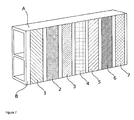
- the grading was made such that the composition of the electrode at the inlet was the least reforming active, and with the activity increasing towards the outlet (other end) of the tube, as illustrated in Figure 7 ; not all layers are shown.
- Layer 1 consisted of LSCM, (La 1-x Sr x ) s (Cr 1-y Mn y )O 3- ⁇
- layer 10 consisted of 95 vol% NiO and 5 vol% LSCM.
- Layers 2 to 6 consisted of a linear grading with Layer 4 having a 1:1 ratio. The electrochemical activity for conversion of H 2 is low for LSCM and high for Ni.
- Suspensions for spraying were manufactured by means of ball milling of powders with polyvinyl pyrrolidone (PVP), polyvinyl butyral (PVB) and EtOH + MEK as additives.
- PVP polyvinyl pyrrolidone
- PVB polyvinyl butyral
- EtOH + MEK EtOH + MEK
- the tube was then sintered at 1100-1400°C in air.
- Example 10 (segmented cell design)
- a flat-tubular SOFC design was obtained, where the composition of the anode was graded along the segmented-flat-tube cell.
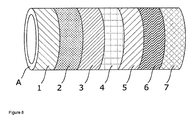
- the grading was obtained by the composition of the individual segments changing from segment to segment such that the inlet was the least reforming active, and with activity increasing towards the outlet of the module/cell, as illustrated in Figure 8 .
- Layer 1 consisted of LSCM, (La 1-x Sr x ) s (Cr 1-y Mn y )O 3- ⁇
- layer 10 consisted of 95 vol% NiO and 5 vol% LSCM.
- Layers 2 to 10 consisted of a linear grading with Layer 6 having a 1:1 ratio.
- the first step was the manufacture of ten inks.
- Suspensions for screen printing were manufactured by means of ball milling of powders with polyvinyl pyrrolidone (PVP), polyvinyl butyral (PVB) and EtOH + MEK as additives.
- PVP polyvinyl pyrrolidone
- PVB polyvinyl butyral
- EtOH + MEK EtOH + MEK
- the cell was subsequently sintered at 1150°C in air.
- the electrolyte layers, cathode and sealants were afterwards deposited and the whole assembly sintered in air at 1250°C.
- Example 11 production of a membrane for syngas production with a graded anode
- a device for the production of synthesis gas was obtained. Methane was fed to one side of a membrane, and air to the other.
- the membrane was a mixed oxide ion/electronic conductor with a thickness of about 10 micrometer. To provide sufficient strength, the membrane was placed on an inert support structure with a thickness of several hundred micrometer.
- step 1 a support tape (CGO or MgO) with a thickness of 400 micrometer was obtained.
- step 2 a graded structure "anode or catalyst layer" as outlined in example 1 was produced. Said layer was made by combining 10 tapes of different composition:
- the tapes were placed on a mylar support and laminated as outlined in Example 1.
- step 3 the catalyst layer tape was laminated together with the manufactured support tape.
- step 4 the support and catalyst layer tape were laminated with a 25 micrometer thick membrane tape which was based on CGO.
- step 5 the laminate was sintered at 1300°C for 5 hours.
- step 6 an oxygen reduction catalyst was applied on the membrane surface.
- Said layer was applied by screen printing a slurry of LSC.
- step 7 the cathode was sintered.
- Example 12 Membrane for syngas production with a horizontally graded cathode
- a membrane for the same purpose as described in example 11 and manufactured in the same way was obtained.
- a horizontal grading is achieved such that the composition changes in the direction of the air flow.
- La 0.2 Sr 0.8 CoO 3 is used, and down stream the air side materials with less and less Sr doping are applied.
- Example 13 Membrane for oxygen production with a horizontally graded electrode
- a membrane for oxygen production operating at high temperature between pressurized air and a pure oxygen permeate stream was obtained.
- the electrode composition varies down stream of the pressurized air such that the Sr content is gradually reduced going down stream the pressurized air 1) SrCoO 2.5 , 2) La 0.3 Sr 0.7 CoO 3 , 3) La 0.6 Sr 0.4 CoO 3 .
- the membrane was obtained as described in example 11.
- the support tape was obtained.
- the catalyst a Ru based supported catalyst was tape cast.
- Step 3 was the manufacture of a graded tape for later lamination.
- Tape 1 consisted of La 0.6 Sr 0 . 4 Fe 0.8 Cr 0.2 O 3
- tape 2 consisted of La 0 . 6 Sr 0.4 Fe 0.9 Cr 0.1 O 3
- tape 3 consisted of La 0.6 Sr 0.4 FeO 3
- tape 4 consisted of La 0.6 Sr 0.4 Feo 0.9 Co 0.1 O 3 .
- Step 4 was the lamination of the obtained tapes on each other.
- Step 5 was the sintering of the obtained laminate.
- step 6 the cathode was applied on the sintered structure so as to obtain the membrane.
- the obtained membrane design is especially suitable for use in a counter flow device. Methane enters (and air exits) at the LSFCr side (hot and very reducing). Syngas exits and air is fed at the LSFeCo side (cold but less reducing).
- Example 15 (Supported membrane with stepwise change in the membrane composition, screen printing)
- a device was obtained as described in example 11, with the exception that the membrane composition changes stepwise and the membrane layers are made by screen printing.
- Step 1 was the manufacture of a MgO support by extrusion or tape casting.
- step 2 the support was sintered for two hours at about 1300°C.
- step 3 the catalyst was applied by dip coating the support in a very thin slurry comprising ultrafine catalyst particles in form of a suspension.
- Step 4 was the application of membrane layers in a sequence of printings, where first of all, the upstream segment was printed, consisting of (La 0.6 Sr 0.4 Fe 0.8 Cr 0.2 O 3 ), and subsequently four more segments were printed such that a small overlap at the border between neighbouring segments is ensured.
- the composition varied from segment to segment in the same manner as outlined in example 11.
- step 5 the component was sintered at 1325°C for four hours.
- step 6 a porous catalyst layer was applied on top of the membrane layer by spraying so as to obtain the supported membrane.
- Example 16 (Supported membrane with stepwise change in the membrane composition, vacuum plasma spraying)
- step 4 was replaced by a membrane application step by vacuum plasma spraying.
- the grading is achieved using several guns connected to different feeds.
- Example 17 Powdered and graded corrosion protection coating manufactured by “ink jet printing”.
- ferritic Fe/Cr steels used as interconnects must be provided by suitable protective coatings.
- Both (La,Sr)CoO 3 and Al 2 O 3 are excellent protection material for prolonging the lifetime of steels like Crofer22APU.
- In a stack where electrical contact is only needed over a fraction of the area it is desirable to apply an Al 2 O 3 rich coating over the none current carrying areas and an (La,Sr)CoO 3 rich coating over the current carrying areas.
- a corrugated plate is considered where the cross section has the shape of a sinusoidal.
- the plate is provided with a protective coat applied in strips (See Fig. 9 ).
- a coating of Al 2 O 3 20 % and (La,Sr) CoO 3 80% was applied by printing (layer A, Fig 9 ).
- a 80% Al 2 O 3 and 20 % (La,Sr)CoO 3 coating was applied by printing (layer B, Fig. 9 ) using an ink-jet-type printing device specially suited for application of particulate slurries of the type described here.
- the jet was fed from two different cartridges containing the two slurries here preferred.
- the coat was applied in a line to line printing operation where the feed changes whenever jet moves in and out of the contact zones (see Figure 9 ).
- Example 18 (Graded corrosion protection coating manufactured by air spraying)
- the temperature in a stack varies in the air flow direction, as outlined above. This results in the air exit region being the most critical for corrosion protection.
- the interconnect is protectedby a sprayed coating where the composition varied from Al 2 O 3 /(LaSr)CoO 3 50/50 in the outlet region to (LaSr)CoO3 in the inlet region.
- the grading was achieved by spraying from multiple containers as outlined above for Example 1.
- Figure 10 illustrates the obtained structure.
- Example 19 formation of a SOFC anode for reformed natural gas- LSCM/Ni
- An SOFC anode for reformed natural gas having a graded composition parallel to the direction of the anode gas flow is obtained.
- the compositions of each of the layers are formed such that an increased electrochemical activity from right to left (gas inlet to outlet) is achieved.
- the multilayer structure is illustrated in Figure 2 .
- Layer 1 consists of LSCM, (La 1-x Sr x ) s (Cr 1-y Mn y )O 3- ⁇
- layer 7 consists of 95 vol% NiO and 5 vol% LSCM. is obtained in seven steps.
- Layers 2 to 6 consist of a linear grading with Layer 4 having a 1:1 ratio. The electrochemical conversion for H 2 is low for LSCM, and high for Ni.
- Suspensions for tape-casting are manufactured by means of ball milling of powders with polyvinyl pyrrolidone (PVP), polyvinyl butyral (PVB) and EtOH + MEK as additives.
- PVP polyvinyl pyrrolidone
- PVB polyvinyl butyral
- EtOH + MEK EtOH + MEK
- the tapes were placed onto a Mylar foil as a support layer, as illustrated in Figure 2 , and laminated by employing heated rolls in a double roll set-up, wherein the lamination took place in one pass.
- the temperature was about 140°C and the pressure was about 1 bar.
- the obtained laminated graded anode was ready to be build into any type of SOC cell.
- Example 20 formation of a SOFC anode for reformed natural gas - YSZ- LSCM/Ni
- An SOFC anode for reformed natural gas having a graded composition parallel to the direction of the anode gas flow is obtained.
- the compositions of the layers are formed such that there is an increased electrochemical activity going from right to left (gas inlet to outlet).
- the Example is illustrated in Figure 2 .
- Layer 1 consists of 40 vol% yttria stabilized zirconia (YSZ) and 60 vol% LSCM, (La 1-x Sr x ) s (Cr 1-y Mn y )O 3- ⁇
- layer 7 consists of 40 vol% YSZ, 50 vol% NiO and 5 vol% LSCM.
- Layers 2 to 6 consist of a linear grading with Layer 4 having a 1:1 ratio of LSCM and NiO, The YSZ is kept constant at 45 vol% and LSCM and NiO sums to 55 vol%.
- the electrochemical activity for conversion of H 2 is low for LSCM and high for Ni.
- Suspensions for tape-casting are manufactured by means of ball milling of powders with polyvinyl pyrrolidone (PVP), polyvinyl butyral (PVB) and EtOH + MEK as additives.
- PVP polyvinyl pyrrolidone
- PVB polyvinyl butyral
- EtOH + MEK EtOH + MEK
- the tapes were placed onto a Mylar foil (support layer) as illustrated in Figure 2 and laminated by employing heated rolls in a double roll set-up, wherein the lamination took place in one pass.
- the temperature was about 140°C and the pressure was about 1 bar.
- the laminated graded anode was ready to be build into any type of SOC cell.
- Example 20 The anode obtained in Example 20 was built in an anode supported solid oxide cell. In the first step, two tapes were produced: an anode support tape (AS) and an electrolyte tape (E). Suspensions for tape-casting are manufactured and cast as described in Example 1.
- AS anode support tape
- E electrolyte tape
- AS-layer The suspension comprised 45 vol% yttria stabilized zirconia (YSZ) and about 55 vol% NiO powder.
- the green thickness of the tape-cast layer was about 400 ⁇ m.
- the porosity of this layer was about 30% after sintering and reduction.
- E-layer The suspension comprised scandia yttria stabilized zirconia (SYSZ) the green thickness of the tape-cast layer was about 15 ⁇ m.
- SYSZ scandia yttria stabilized zirconia
- the AS and E tapes were laminated together with a graded tape manufactured as described in Example 20.
- the order of lamination was: AS/graded anode/E.
- Lamination is performed by employing heated rolls in a double roll set-up. The temperature was about 140°C and the pressure was about 1 bar.
- the laminated tapes were cut into the desired shapes. This was done by knife punching resulting in areas of 12x12 cm 2 after sintering.
- the half-cell was sintered.
- the half-cell was placed in a furnace and sintered at about 1300°C and left for about 12 hours before cooling to room temperature.
- a cathode was deposited on the sintered half-cell by screen printing an ink comprising a 1:1 weight ratio mixture of La 0.75 Sr 0.25 MnO 3- ⁇ and SYSZ on the surface of the electrolyte layer (E).
- the thickness of the printed layer was 30 ⁇ m before sintering.
- the sixth step was the sintering of the cell in a furnace at about 1100°C for 2 hours before cooling to room temperature so as to obtain the SOC.
- Example 22 formation of an anode for direct conversion of natural gas
- compositions of the five layers were as follows:
- the tapes were manufactured and laminated as described in Example 20.
- Example 23 The anode obtained in Example 23 was built in an electrolyte supported cell.
- the SOFC anode for non-reformed natural gas had a graded composition parallel to the direction of the gas flow.
- the compositions of the layers were made such that there was an increased electrochemical activity going from right to left (gas inlet to outlet), as illustrated in Figure 4 .
- the first step was the manufacture of five screen printing inks having the compositions as given above.
- the second step was the deposition of the layers side by side by screen printing.
- Example 22 The cell was completed as outlined in Example 22.
- the electrochemical activity of the cathode is balanced in this example.
- the temperature in the four stack corners will under normal operational conditions be of a lower temperature as compared to the center of the stack as follows: T (air out -H 2 in) > T (air in - H 2 in) > T (air out-H 2 out) >T (air in-H 2 out).
- the temperature distribution on the cathode side is levelled/controlled by having a cross gradient as illustrated in Figure 5 .
- the compositions of the layers are as follows:
- the tapes are manufactured and laminated as described in Example 20.
- T air out -H 2 in
- T air in - H 2 in
- T air out-H 2 out
- T air in-H 2 out
- the temperature distribution on the cathode side is levelled/controlled by having a cross gradient as illustrated in Figure 5 .
- the compositions of the layers are as follows:
- the tapes are manufactured and laminated as described in Example 20 in order to obtain the SOC cathode.
Landscapes
- Chemical & Material Sciences (AREA)
- Chemical Kinetics & Catalysis (AREA)
- Engineering & Computer Science (AREA)
- Electrochemistry (AREA)
- General Chemical & Material Sciences (AREA)
- Manufacturing & Machinery (AREA)
- Materials Engineering (AREA)
- Inorganic Chemistry (AREA)
- Organic Chemistry (AREA)
- Metallurgy (AREA)
- Mechanical Engineering (AREA)
- Life Sciences & Earth Sciences (AREA)
- Sustainable Development (AREA)
- Sustainable Energy (AREA)
- Ceramic Engineering (AREA)
- Composite Materials (AREA)
- Inert Electrodes (AREA)
- Fuel Cell (AREA)
- Secondary Cells (AREA)
- Cell Separators (AREA)
- Laminated Bodies (AREA)
Priority Applications (1)
| Application Number | Priority Date | Filing Date | Title |
|---|---|---|---|
| EP20080015279 EP2031682A3 (fr) | 2007-08-31 | 2008-08-29 | Structures calibrées horizontalement pour des dispositifs électrochimiques et électroniques |
Applications Claiming Priority (2)
| Application Number | Priority Date | Filing Date | Title |
|---|---|---|---|
| EP07017110A EP2031681A1 (fr) | 2007-08-31 | 2007-08-31 | Structures étagées horizontalement pour des dispositifs électrochimiques et électroniques |
| EP20080015279 EP2031682A3 (fr) | 2007-08-31 | 2008-08-29 | Structures calibrées horizontalement pour des dispositifs électrochimiques et électroniques |
Publications (2)
| Publication Number | Publication Date |
|---|---|
| EP2031682A2 true EP2031682A2 (fr) | 2009-03-04 |
| EP2031682A3 EP2031682A3 (fr) | 2009-09-02 |
Family
ID=38974675
Family Applications (2)
| Application Number | Title | Priority Date | Filing Date |
|---|---|---|---|
| EP07017110A Withdrawn EP2031681A1 (fr) | 2007-08-31 | 2007-08-31 | Structures étagées horizontalement pour des dispositifs électrochimiques et électroniques |
| EP20080015279 Withdrawn EP2031682A3 (fr) | 2007-08-31 | 2008-08-29 | Structures calibrées horizontalement pour des dispositifs électrochimiques et électroniques |
Family Applications Before (1)
| Application Number | Title | Priority Date | Filing Date |
|---|---|---|---|
| EP07017110A Withdrawn EP2031681A1 (fr) | 2007-08-31 | 2007-08-31 | Structures étagées horizontalement pour des dispositifs électrochimiques et électroniques |
Country Status (8)
| Country | Link |
|---|---|
| US (1) | US8802321B2 (fr) |
| EP (2) | EP2031681A1 (fr) |
| JP (1) | JP5117324B2 (fr) |
| KR (3) | KR20090023285A (fr) |
| CN (1) | CN101378132B (fr) |
| AU (1) | AU2008203849B8 (fr) |
| CA (1) | CA2638420C (fr) |
| RU (1) | RU2380790C1 (fr) |
Cited By (1)
| Publication number | Priority date | Publication date | Assignee | Title |
|---|---|---|---|---|
| FR2945378A1 (fr) * | 2009-05-11 | 2010-11-12 | Commissariat Energie Atomique | Cellule de pile a combustible haute temperature a reformage interne d'hydrocarbures. |
Families Citing this family (20)
| Publication number | Priority date | Publication date | Assignee | Title |
|---|---|---|---|---|
| EP1184442A1 (fr) | 2000-08-30 | 2002-03-06 | Clariant International Ltd. | Composition liquide cristalline |
| FR2914783A1 (fr) | 2007-04-03 | 2008-10-10 | St Microelectronics Sa | Procede de fabrication d'un dispositif a gradient de concentration et dispositif correspondant. |
| KR101084730B1 (ko) * | 2009-04-20 | 2011-11-22 | 한국과학기술원 | 연료전지를 이용하는 전기 및 유기화합물의 동시 제조방법, 연료전지 전극용 촉매, 및 상기 촉매를 포함하는 연료전지 |
| CN101768380B (zh) * | 2009-12-30 | 2014-12-17 | 中国科学院上海硅酸盐研究所 | 成分梯度变化的热防护涂层及制备方法 |
| RU2414776C1 (ru) * | 2010-02-09 | 2011-03-20 | Учреждение Российской академии наук Институт электрофизики Уральского отделения РАН (ИЭФ УрО РАН) | Устойчивая суспензия изопропанольного шликера на поливинилбутиральной связке из нанопорошка с добавлением дисперсанта (варианты) и способ его получения |
| CN101799333B (zh) * | 2010-04-08 | 2011-08-03 | 山东大学 | 一种测温或电加热用的耐蚀性薄膜及其坩埚元件 |
| US20120251917A1 (en) * | 2011-04-04 | 2012-10-04 | Korea Institute Of Science And Technology | Solid oxide fuel cell comprising nanostructure composite cathode and fabrication method thereof |
| KR101959738B1 (ko) | 2012-05-24 | 2019-03-19 | 삼성전자 주식회사 | 장치 식별자와 사용자 인증 정보에 기반한 보안 키 생성 장치 |
| CN104798237B (zh) | 2012-11-20 | 2018-12-14 | 博隆能源股份有限公司 | 经掺杂氧化钪稳定的氧化锆电解质组合物 |
| RU2522188C1 (ru) * | 2013-03-26 | 2014-07-10 | Федеральное государственное бюджетное учреждение науки Институт высокотемпературной электрохимии Уральского отделения Российской Академии наук | Способ получения двухслойного несущего катода для твердооксидных топливных элементов |
| CN103441293B (zh) * | 2013-08-30 | 2015-04-22 | 哈尔滨工业大学 | 一种利用固体氧化物燃料电池中元素高温扩散的方法制备阳极/电解质半电池的方法 |
| CN103556098B (zh) * | 2013-11-01 | 2015-11-18 | 中国科学院上海硅酸盐研究所 | 一种抗火山灰侵蚀的多层热障涂层 |
| RU2542752C1 (ru) * | 2014-02-11 | 2015-02-27 | Федеральное государственное бюджетное учреждение науки Институт высокотемпературной электрохимии Уральского отделения Российской Академии наук | Способ изготовления пористых катодных материалов на основе манганита лантана-стронция |
| JP6654903B2 (ja) * | 2016-01-13 | 2020-02-26 | 株式会社ノリタケカンパニーリミテド | 固体酸化物形燃料電池用の電極材料とその利用 |
| CN106025315B (zh) * | 2016-07-25 | 2019-03-29 | 合肥工业大学 | 一种改性lscm电极及其制备方法 |
| WO2020025102A1 (fr) * | 2018-07-30 | 2020-02-06 | Applied Materials, Inc. | Procédé de revêtement d'un substrat souple avec un empilement de couches, empilement de couches et appareil de dépôt pour le revêtement d'un substrat souple avec un empilement de couches |
| KR102814299B1 (ko) * | 2018-09-14 | 2025-05-30 | 주식회사 엘지화학 | 고체 산화물 연료전지용 양극 및 이의 제조 방법 |
| CN110993997A (zh) * | 2019-12-23 | 2020-04-10 | 福州大学 | 一种提高可逆固体氧化物电池运行稳定性的方法 |
| WO2022072143A1 (fr) * | 2020-10-01 | 2022-04-07 | Phillips 66 Company | Électrode oxydoréductrice de cellules électrochimiques à oxyde solide |
| JPWO2024201640A1 (fr) * | 2023-03-27 | 2024-10-03 |
Citations (10)
| Publication number | Priority date | Publication date | Assignee | Title |
|---|---|---|---|---|
| US4329403A (en) | 1981-04-27 | 1982-05-11 | Energy Research Corporation | Electrolyte-electrode assembly for fuel cells |
| US5171645A (en) | 1991-01-08 | 1992-12-15 | Gas Research Institute, Inc. | Zirconia-bismuth oxide graded electrolyte |
| US5543239A (en) | 1995-04-19 | 1996-08-06 | Electric Power Research Institute | Electrode design for solid state devices, fuel cells and sensors |
| US6228521B1 (en) | 1998-12-08 | 2001-05-08 | The University Of Utah Research Foundation | High power density solid oxide fuel cell having a graded anode |
| US20040086633A1 (en) | 2002-11-04 | 2004-05-06 | Lemmon John P. | Systems and methods for the fabrication of solid oxide fuel cell components using liquid spraying |
| EP1441406A2 (fr) | 2003-01-16 | 2004-07-28 | Hewlett-Packard Development Company, L.P. | Pile à combustible avec une composition catalytique adaptée |
| US20050092597A1 (en) | 2003-10-29 | 2005-05-05 | O'neil James | Method of forming thin-film electrodes |
| EP1701402A1 (fr) | 2005-03-08 | 2006-09-13 | General Electric Company | Systèmes et méthodes de minimisation de différences et de gradients de température dans une pile à combustible à oxyde solide |
| EP1760817A1 (fr) | 2005-08-31 | 2007-03-07 | Technical University of Denmark | Pile à combustible réversible et méthode de fabrication |
| EP1930974A1 (fr) | 2006-11-23 | 2008-06-11 | Technical University of Denmark | Méthode de fabrication de piles reversibles à oxyde solide |
Family Cites Families (25)
| Publication number | Priority date | Publication date | Assignee | Title |
|---|---|---|---|---|
| US1441406A (en) * | 1921-01-18 | 1923-01-09 | William R Dales | Infant's nursing device |
| US1701402A (en) * | 1926-03-22 | 1929-02-05 | Gen Motors Corp | Vibration neutralizer |
| JPH0785874A (ja) | 1993-09-16 | 1995-03-31 | Fuji Electric Co Ltd | 燃料電池の燃料電極 |
| ATE245852T1 (de) * | 1995-10-06 | 2003-08-15 | Dow Global Technologies Inc | Fluessigkeitsverteilungsstrukturen fuer membran- elektrode-anordnungen von brennstoffzellen |
| RU2125324C1 (ru) * | 1996-11-11 | 1999-01-20 | Горина Лилия Федоровна | Способ изготовления единичного высокотемпературного топливного элемента и его компонентов: катода, электролита, анода, токопрохода, интерфейсного и электроизолирующего слоев |
| US6605316B1 (en) * | 1999-07-31 | 2003-08-12 | The Regents Of The University Of California | Structures and fabrication techniques for solid state electrochemical devices |
| CN1409427A (zh) * | 2001-09-18 | 2003-04-09 | 中国科学技术大学 | 一种中温固体氧化物燃料电池pen多层膜及其制造方法 |
| JP4269611B2 (ja) | 2001-09-19 | 2009-05-27 | 旭硝子株式会社 | 固体高分子型燃料電池用膜電極接合体の製造方法 |
| CA2404175A1 (fr) * | 2001-09-19 | 2003-03-19 | Asahi Glass Company, Limited | Procede de production d'electrodes a membrane pour pile a combustible a electrolyte polymere solide |
| JP2003173785A (ja) * | 2001-12-05 | 2003-06-20 | Mitsubishi Electric Corp | 固体高分子型燃料電池用触媒層の形成方法及びその形成装置 |
| US6824907B2 (en) * | 2002-01-16 | 2004-11-30 | Alberta Reasearch Council, Inc. | Tubular solid oxide fuel cell stack |
| US20040058227A1 (en) * | 2002-07-09 | 2004-03-25 | Matsushita Electric Industrial Co., Ltd. | Electrolyte membrane-electrode assembly for a fuel cell, fuel cell using the same and method of making the same |
| JP2004079332A (ja) * | 2002-08-19 | 2004-03-11 | Mitsubishi Materials Corp | 固体酸化物形燃料電池用電極層の形成方法 |
| RU2224337C1 (ru) * | 2002-10-22 | 2004-02-20 | ООО "Салют Текнолоджис Вест" | Способ изготовления высокотемпературного топливного элемента и установка для его осуществления |
| CN1492530A (zh) * | 2002-10-24 | 2004-04-28 | 江苏隆源双登电源有限公司 | 燃料电池膜电极的制作工艺 |
| US20040180252A1 (en) * | 2003-03-14 | 2004-09-16 | General Electric Company | Fuel cell and method for manufacturing fuel cell |
| US7244526B1 (en) * | 2003-04-28 | 2007-07-17 | Battelle Memorial Institute | Solid oxide fuel cell anodes and electrodes for other electrochemical devices |
| RU2236068C1 (ru) * | 2003-06-10 | 2004-09-10 | Мятиев Ата Атаевич | Электрод-электролитная пара на основе двуокиси циркония (варианты), способ ее изготовления (варианты) и органогель |
| US7923172B2 (en) * | 2003-11-14 | 2011-04-12 | Basf Fuel Cell Gmbh | Structures for gas diffusion materials and methods for their fabrication |
| JP2005310737A (ja) * | 2004-03-23 | 2005-11-04 | Toto Ltd | 固体酸化物形燃料電池 |
| JP4855708B2 (ja) * | 2005-04-25 | 2012-01-18 | パナソニック株式会社 | 電極フープの圧延方法 |
| JP2006331743A (ja) * | 2005-05-24 | 2006-12-07 | Kyocera Corp | 横縞形燃料電池セル、その製造方法、燃料電池セルスタック、その製造方法、および、燃料電池、 |
| ATE402494T1 (de) * | 2005-09-06 | 2008-08-15 | Sgl Carbon Ag | Elektroden für brennstoffzellen |
| KR100717130B1 (ko) * | 2005-09-30 | 2007-05-11 | 한국과학기술연구원 | 고체산화물 연료전지용 페이스트, 이를 이용한 연료극지지형 고체산화물 연료전지 및 그 제조 방법 |
| CN101346848B (zh) * | 2005-11-08 | 2014-08-06 | A·德沃 | 包括具有热部分和冷部分的细长基体的固体氧化物燃料电池装置 |
-
2007
- 2007-08-31 EP EP07017110A patent/EP2031681A1/fr not_active Withdrawn
-
2008
- 2008-07-25 RU RU2008131143/09A patent/RU2380790C1/ru not_active IP Right Cessation
- 2008-07-30 CA CA2638420A patent/CA2638420C/fr not_active Expired - Fee Related
- 2008-08-13 AU AU2008203849A patent/AU2008203849B8/en not_active Ceased
- 2008-08-14 US US12/191,568 patent/US8802321B2/en not_active Expired - Fee Related
- 2008-08-29 CN CN2008102101514A patent/CN101378132B/zh not_active Expired - Fee Related
- 2008-08-29 JP JP2008220724A patent/JP5117324B2/ja not_active Expired - Fee Related
- 2008-08-29 EP EP20080015279 patent/EP2031682A3/fr not_active Withdrawn
- 2008-08-29 KR KR1020080085182A patent/KR20090023285A/ko not_active Ceased
-
2011
- 2011-03-07 KR KR1020110020001A patent/KR20110043555A/ko not_active Ceased
-
2012
- 2012-05-14 KR KR1020120050890A patent/KR20120055527A/ko not_active Abandoned
Patent Citations (10)
| Publication number | Priority date | Publication date | Assignee | Title |
|---|---|---|---|---|
| US4329403A (en) | 1981-04-27 | 1982-05-11 | Energy Research Corporation | Electrolyte-electrode assembly for fuel cells |
| US5171645A (en) | 1991-01-08 | 1992-12-15 | Gas Research Institute, Inc. | Zirconia-bismuth oxide graded electrolyte |
| US5543239A (en) | 1995-04-19 | 1996-08-06 | Electric Power Research Institute | Electrode design for solid state devices, fuel cells and sensors |
| US6228521B1 (en) | 1998-12-08 | 2001-05-08 | The University Of Utah Research Foundation | High power density solid oxide fuel cell having a graded anode |
| US20040086633A1 (en) | 2002-11-04 | 2004-05-06 | Lemmon John P. | Systems and methods for the fabrication of solid oxide fuel cell components using liquid spraying |
| EP1441406A2 (fr) | 2003-01-16 | 2004-07-28 | Hewlett-Packard Development Company, L.P. | Pile à combustible avec une composition catalytique adaptée |
| US20050092597A1 (en) | 2003-10-29 | 2005-05-05 | O'neil James | Method of forming thin-film electrodes |
| EP1701402A1 (fr) | 2005-03-08 | 2006-09-13 | General Electric Company | Systèmes et méthodes de minimisation de différences et de gradients de température dans une pile à combustible à oxyde solide |
| EP1760817A1 (fr) | 2005-08-31 | 2007-03-07 | Technical University of Denmark | Pile à combustible réversible et méthode de fabrication |
| EP1930974A1 (fr) | 2006-11-23 | 2008-06-11 | Technical University of Denmark | Méthode de fabrication de piles reversibles à oxyde solide |
Non-Patent Citations (4)
| Title |
|---|
| HENDRIKSEN, P. V.: "Model studies of internal steam reforming in SOFC stacks", PROCEEDINGS - ELECTROCHEMICAL SOCIETY, 1997, pages 97 - 40 |
| J.A. LABRINCHA ET AL.: "Evaluation of deposition techniques of cathode materials for solid oxide fuel cells", MAT. RES. BULL., vol. 28, 1993, pages 101 - 109 |
| N. Q. MINH; T. TAKAHASHI: "Science and Technology of Ceramic Fuel Cells", 1995, ELSEVIER SCIENCE B. V. |
| Z. WANG ET AL.: "A study of multilayer tape casting method for anode-supported planar type solid oxide fuel cells", JOURNAL OF ALLOYS AND COMPOUNDS, vol. 437, 2007, pages 264 - 268 |
Cited By (1)
| Publication number | Priority date | Publication date | Assignee | Title |
|---|---|---|---|---|
| FR2945378A1 (fr) * | 2009-05-11 | 2010-11-12 | Commissariat Energie Atomique | Cellule de pile a combustible haute temperature a reformage interne d'hydrocarbures. |
Also Published As
| Publication number | Publication date |
|---|---|
| AU2008203849B8 (en) | 2010-07-15 |
| AU2008203849B2 (en) | 2010-03-04 |
| KR20110043555A (ko) | 2011-04-27 |
| US8802321B2 (en) | 2014-08-12 |
| JP2009059699A (ja) | 2009-03-19 |
| KR20120055527A (ko) | 2012-05-31 |
| CN101378132B (zh) | 2011-10-19 |
| CA2638420A1 (fr) | 2009-02-28 |
| US20090061287A1 (en) | 2009-03-05 |
| RU2380790C1 (ru) | 2010-01-27 |
| EP2031681A1 (fr) | 2009-03-04 |
| KR20090023285A (ko) | 2009-03-04 |
| CN101378132A (zh) | 2009-03-04 |
| JP5117324B2 (ja) | 2013-01-16 |
| EP2031682A3 (fr) | 2009-09-02 |
| AU2008203849A1 (en) | 2009-03-19 |
| CA2638420C (fr) | 2013-09-24 |
Similar Documents
| Publication | Publication Date | Title |
|---|---|---|
| US8802321B2 (en) | Horizontally graded structures for electrochemical and electronic devices | |
| JP5767297B2 (ja) | 積層型固体酸化物形燃料電池用スタック構造体、積層型固体酸化物形燃料電池及びその製造方法 | |
| JP5546596B2 (ja) | 可逆的固体酸化物電池を製造する改良された方法 | |
| EP1932202B1 (fr) | Membranes ceramiques a joints et support integres, ainsi que piles electrochimiques et empilements de piles electrochimiques comprenant lesdites membranes | |
| US12119526B2 (en) | Metal support for electrochemical element, electrochemical element, electrochemical module, electrochemical device, energy system, solid oxide fuel cell, solid oxide electrolytic cell, and method for manufacturing metal support | |
| EP1334528A1 (fr) | Piles a combustible | |
| US11670779B2 (en) | Metal support for electrochemical element, electrochemical element, electrochemical module, electrochemical device, energy system, solid oxide fuel cell, solid oxide electrolytic cell, and method for manufacturing metal support | |
| US20060234100A1 (en) | Self-supporting ceramic membranes and electrochemical cells and cell stacks including the same | |
| US11791477B2 (en) | Roll-to-roll SOFC manufacturing method and system | |
| EP3790092B1 (fr) | Corps de support métallique pour élément électrochimique, élément électrochimique, module électrochimique, dispositif électrochimique, système d'énergie, pile à combustible à oxyde solide, et procédé de production pour corps de support métallique | |
| HK1130119A (en) | Horizontally graded structures for electrochemical and electronic devices | |
| HK1054123B (en) | Fuel cells |
Legal Events
| Date | Code | Title | Description |
|---|---|---|---|
| PUAI | Public reference made under article 153(3) epc to a published international application that has entered the european phase |
Free format text: ORIGINAL CODE: 0009012 |
|
| AK | Designated contracting states |
Kind code of ref document: A2 Designated state(s): AT BE BG CH CY CZ DE DK EE ES FI FR GB GR HR HU IE IS IT LI LT LU LV MC MT NL NO PL PT RO SE SI SK TR |
|
| AX | Request for extension of the european patent |
Extension state: AL BA MK RS |
|
| PUAL | Search report despatched |
Free format text: ORIGINAL CODE: 0009013 |
|
| AK | Designated contracting states |
Kind code of ref document: A3 Designated state(s): AT BE BG CH CY CZ DE DK EE ES FI FR GB GR HR HU IE IS IT LI LT LU LV MC MT NL NO PL PT RO SE SI SK TR |
|
| AX | Request for extension of the european patent |
Extension state: AL BA MK RS |
|
| REG | Reference to a national code |
Ref country code: HK Ref legal event code: DE Ref document number: 1130119 Country of ref document: HK |
|
| 17P | Request for examination filed |
Effective date: 20100223 |
|
| AKX | Designation fees paid |
Designated state(s): AT BE BG CH CY CZ DE DK EE ES FI FR GB GR HR HU IE IS IT LI LT LU LV MC MT NL NO PL PT RO SE SI SK TR |
|
| 17Q | First examination report despatched |
Effective date: 20110714 |
|
| RIC1 | Information provided on ipc code assigned before grant |
Ipc: C23C 28/04 20060101AFI20150422BHEP Ipc: H01M 4/86 20060101ALI20150422BHEP Ipc: H01M 4/88 20060101ALI20150422BHEP Ipc: H01M 8/12 20060101ALI20150422BHEP |
|
| GRAP | Despatch of communication of intention to grant a patent |
Free format text: ORIGINAL CODE: EPIDOSNIGR1 |
|
| INTG | Intention to grant announced |
Effective date: 20150625 |
|
| REG | Reference to a national code |
Ref country code: HK Ref legal event code: WD Ref document number: 1130119 Country of ref document: HK |
|
| STAA | Information on the status of an ep patent application or granted ep patent |
Free format text: STATUS: THE APPLICATION IS DEEMED TO BE WITHDRAWN |
|
| 18D | Application deemed to be withdrawn |
Effective date: 20151106 |