EP2031723B3 - Abstandshalter für den Einbau in einer Leichtbauplatte - Google Patents
Abstandshalter für den Einbau in einer Leichtbauplatte Download PDFInfo
- Publication number
- EP2031723B3 EP2031723B3 EP08014559.2A EP08014559A EP2031723B3 EP 2031723 B3 EP2031723 B3 EP 2031723B3 EP 08014559 A EP08014559 A EP 08014559A EP 2031723 B3 EP2031723 B3 EP 2031723B3
- Authority
- EP
- European Patent Office
- Prior art keywords
- spacer
- legs
- dorsal shield
- plate
- facing away
- Prior art date
- Legal status (The legal status is an assumption and is not a legal conclusion. Google has not performed a legal analysis and makes no representation as to the accuracy of the status listed.)
- Not-in-force
Links
- 238000009434 installation Methods 0.000 title description 4
- 238000010276 construction Methods 0.000 title description 2
- 125000006850 spacer group Chemical group 0.000 claims abstract description 63
- 239000002861 polymer material Substances 0.000 claims abstract description 6
- 229920001169 thermoplastic Polymers 0.000 claims abstract description 3
- RNFJDJUURJAICM-UHFFFAOYSA-N 2,2,4,4,6,6-hexaphenoxy-1,3,5-triaza-2$l^{5},4$l^{5},6$l^{5}-triphosphacyclohexa-1,3,5-triene Chemical compound N=1P(OC=2C=CC=CC=2)(OC=2C=CC=CC=2)=NP(OC=2C=CC=CC=2)(OC=2C=CC=CC=2)=NP=1(OC=1C=CC=CC=1)OC1=CC=CC=C1 RNFJDJUURJAICM-UHFFFAOYSA-N 0.000 claims description 3
- 239000003063 flame retardant Substances 0.000 claims description 3
- 230000000717 retained effect Effects 0.000 claims 1
- 239000000463 material Substances 0.000 abstract description 3
- 239000000835 fiber Substances 0.000 abstract description 2
- 230000000979 retarding effect Effects 0.000 abstract 1
- 239000011810 insulating material Substances 0.000 description 4
- 239000004952 Polyamide Substances 0.000 description 2
- 239000003365 glass fiber Substances 0.000 description 2
- 229910052736 halogen Inorganic materials 0.000 description 2
- 150000002367 halogens Chemical class 0.000 description 2
- 238000003780 insertion Methods 0.000 description 2
- 230000037431 insertion Effects 0.000 description 2
- 239000012774 insulation material Substances 0.000 description 2
- 239000003562 lightweight material Substances 0.000 description 2
- 229920002647 polyamide Polymers 0.000 description 2
- 239000000654 additive Substances 0.000 description 1
- 230000000996 additive effect Effects 0.000 description 1
- 238000004873 anchoring Methods 0.000 description 1
- 239000006260 foam Substances 0.000 description 1
- 238000002347 injection Methods 0.000 description 1
- 239000007924 injection Substances 0.000 description 1
- 238000009413 insulation Methods 0.000 description 1
- 230000035515 penetration Effects 0.000 description 1
- 230000002093 peripheral effect Effects 0.000 description 1
- 230000000284 resting effect Effects 0.000 description 1
- 239000000243 solution Substances 0.000 description 1
Images
Classifications
-
- H—ELECTRICITY
- H02—GENERATION; CONVERSION OR DISTRIBUTION OF ELECTRIC POWER
- H02G—INSTALLATION OF ELECTRIC CABLES OR LINES, OR OF COMBINED OPTICAL AND ELECTRIC CABLES OR LINES
- H02G3/00—Installations of electric cables or lines or protective tubing therefor in or on buildings, equivalent structures or vehicles
- H02G3/02—Details
- H02G3/08—Distribution boxes; Connection or junction boxes
- H02G3/18—Distribution boxes; Connection or junction boxes providing line outlets
- H02G3/20—Ceiling roses or other lighting sets
-
- F—MECHANICAL ENGINEERING; LIGHTING; HEATING; WEAPONS; BLASTING
- F21—LIGHTING
- F21V—FUNCTIONAL FEATURES OR DETAILS OF LIGHTING DEVICES OR SYSTEMS THEREOF; STRUCTURAL COMBINATIONS OF LIGHTING DEVICES WITH OTHER ARTICLES, NOT OTHERWISE PROVIDED FOR
- F21V15/00—Protecting lighting devices from damage
- F21V15/02—Cages
-
- F—MECHANICAL ENGINEERING; LIGHTING; HEATING; WEAPONS; BLASTING
- F21—LIGHTING
- F21V—FUNCTIONAL FEATURES OR DETAILS OF LIGHTING DEVICES OR SYSTEMS THEREOF; STRUCTURAL COMBINATIONS OF LIGHTING DEVICES WITH OTHER ARTICLES, NOT OTHERWISE PROVIDED FOR
- F21V21/00—Supporting, suspending, or attaching arrangements for lighting devices; Hand grips
- F21V21/02—Wall, ceiling, or floor bases; Fixing pendants or arms to the bases
- F21V21/04—Recessed bases
-
- F—MECHANICAL ENGINEERING; LIGHTING; HEATING; WEAPONS; BLASTING
- F21—LIGHTING
- F21V—FUNCTIONAL FEATURES OR DETAILS OF LIGHTING DEVICES OR SYSTEMS THEREOF; STRUCTURAL COMBINATIONS OF LIGHTING DEVICES WITH OTHER ARTICLES, NOT OTHERWISE PROVIDED FOR
- F21V25/00—Safety devices structurally associated with lighting devices
Definitions
- the present invention relates to a spacer, in particular for the installation of electrical and / or heat-emitting components on a lightweight board.
- a spacer in particular for the installation of electrical and / or heat-emitting components on a lightweight board.
- heat-generating electrical components to be mounted on the lightweight board must be reliably kept away from the insulation material to avoid fire hazards.
- Out DE 43 240 57 C2 is a spacer with a spine shield and two legs protruding therefrom, which is intended to be inserted with the spine shield ahead in an opening of a plate, wherein the two legs the spine shield on the plate by means of bearing on an inner side of the plate bearing surfaces support.
- a problem with this design is that the ring must be exactly adapted to the dimensions of the opening of the plate in which the spacer is to be mounted. For openings in different dimensions therefore numerous different models of the spacer are needed, which makes the production more expensive and makes the use of a craftsman cumbersome, since the different models of the spacer must be kept ready and the right one for each application must be selected. Also, the need for tightening makes the application of this known spacer tedious.
- spacer is off DE 103 35 515 A1 known.
- This consists of two rotatably interconnected, U-shaped curved strip, each strip can be understood as consisting of a back plate and two thereof projecting in a same direction legs and the rotatable connection between the strips is located on each of the spine shield.
- the free ends of the arms are unconnected to this spacer, which makes it possible to push the spacer through wall openings, whose inside width is substantially smaller than the distance between the ends of the legs in the relaxed state.
- the spacer since the spacer is not fixed in position after passing through the opening, can not be excluded that it slips so that the insulating material on the inside of the wall of a mounted in the opening of the heat source comes critically close.
- the object of the invention is to provide a spacer which avoids the above-mentioned disadvantages of the prior art.
- the object of the invention is achieved in that, in the case of a spacer having at least two legs protruding in a same direction from a spine, at least one support surface protruding radially outward from each leg, each leg being in an area between its end facing away from the spine shield and Supporting surface has at least one predetermined breaking point.
- This makes it possible to make the respective areas of the legs significantly longer than the thickness of a plate on which the spacer is to be mounted, so that a user can constantly hold the legs of the legs during the placement of the spacer and accurately guide. Thanks to the predetermined breaking points, after the placement of the spacer over the outside of the plate protruding ends of the legs can be easily removed.
- the object of the invention is further solved by, in a spacer having at least two projecting from a spine in a same direction legs, each leg of at least one support surface projects radially outward, the legs are unconnected at their ends remote from the spine shield.
- the spacer can be used on openings with different diameters, so that a small number of models in different sizes or even a single model of the spacer is sufficient for most practical applications.
- the object of the invention is further solved by the support surfaces preferably in one piece with at least two projecting from a spine in a same direction legs and bearing surfaces, which protrude from the legs at a distance from their ends facing away from the spine shield, the bearing surfaces preferably in one piece with the legs are formed.
- This simplification of the structure of the spacer is possible and practical, since it can be assumed that the spacer is held in place after insertion into an opening by the weight of insulating material resting on it.
- the support surfaces protrude from the legs at a distance from their ends facing away from the spine shield, after insertion of the spacer into an opening in each case a portion of the legs in the opening back, whereby a slipping of the spacer is excluded.
- a solution of the task is further to provide at least one radially outwardly directed mandrel to each leg in a region between its end facing away from the spine shield and the support surface.
- Such a mandrel can be pressed into a plate of suitable material after placing the bearing surfaces on the inside of an opening of the plate be achieved in order to achieve a positive anchoring of the spacer to the plate, regardless of their thickness.
- an electrical load such as a lamp in the plate opening after attachment of the spacer
- a terminal block with electrical contacts to supply the consumer plugged onto a retaining pin of the spacer.
- the clamping block is preferably held by friction on the retaining pin.
- the spine shield is wider than the legs projecting therefrom.
- this is expediently curved in two mutually perpendicular and parallel to the same direction parallel cutting planes.
- the legs are suitably arched in a section transverse to the same direction in a circular arc, in order to achieve a high flexural rigidity with low material thickness.
- the bearing surfaces are expediently laterally broadened beyond the legs which carry them in order to ensure high stability, in particular if the number of legs is only two.
- the spacer may be integrally molded from a thermoplastic polymer material such as polyamide.
- the polymer material is expediently mixed with a flame-retardant additive, and it may be reinforced by fibers, in particular glass fibers.
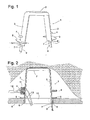
- Fig. 1 shows a perspective view of the spacer according to the invention 1.
- the spacer 1 is injection molded in one piece from glass fiber reinforced, flame retardant polyamide. It comprises a circular back plate 2 in the form of a flat shell, whose concave side in the preferred mounting position of the spacer 1, as shown in the figures, faces downwards.
- two legs 3 extend obliquely apart running down.
- the width of the cross-sectionally circular legs 3 is about one third of the diameter of the spine shield 2.
- the legs 3 From its root on the spine shield 2 to its end facing away from the back plate 2 end, the legs 3 each in turn: a radially outwardly projecting cylindrical pin 4 with a blunt, rounded tip, an approximately at right angles to the longitudinal direction of the legs 3 outwardly projecting tab 5, the width of which is smaller than the diameter of the spine shield 2, but significantly larger than the width of the legs 3, two narrow pointed mandrels 6 and a Breaking point 7.
- the spacer 1 is provided to fit in an opening of a plate 8, as in FIG Fig. 2 shown to be mounted by a user press the two lying beyond the predetermined breaking points 7 end portions 9 of the legs 3 against each other with their fingers, so that the two tabs 5 do not protrude beyond the circumference of the spine shield 2 substantially.
- the spacer 1 can be inserted into an opening 10 of the plate 8, provided that its diameter is at least as large as that of the spine shield second
- a clamping block 11 is attached to each of the two mandrels 6, are attached to the supply cable 12, 13 of a mounted in the wall opening after the spacer 1 halogen lamp.
- the plate 8 is preferably made of plasterboard, a rigid foam or other lightweight material and forms the visible side of a ceiling construction, which contains an insulating material layer 14 in its interior.
- a loose film 15 separates the insulation layer 14 of the plate 8.
- the film 15 rests on the spine shield 2 of the spacer 1.
- the weight of the supported by the spacer 1 insulating layer 14 is transmitted via the tabs 5 on the plate 8.
- the spacer 1 is anchored positively to the plate 8 by the mandrels 6 are pressed from the inside against the edge of the opening 10.
- the distance between the tab 5 and the predetermined breaking point 7 on each leg 3 corresponds to the thickness of the plate 8, so that when the user breaks off the end portions 9 of the legs 3 after placing the spacer 1, as on the left leg 3 in FIG Fig. 2 shown, the spacer 1 no longer protrudes beyond the outside of the plate 14. This ensures that the presence of the spacer 1 does not hinder the mounting of a halogen lamp in the opening 10, whose housing has a flange
- the spikes 6 are flat and thin compared to the tabs 5, on the one hand to facilitate penetration of the spikes 6 into a plasterboard panel or other resilient lightweight material, and on the other hand to give the user the opportunity to cut off the spikes 6 with a knife prior to the placement of the spacer 1 when the plate 8 in which the spacer 1 is to be mounted is too hard to press the spikes 6 therein.
- more than two legs 3 may be evenly distributed on the circumference of the spine shield 2, there may be several predetermined breaking points 7 successively provided on the legs 3 to the end portions 9 respectively to match the thickness of the plate 8, in which the spacer 1 is mounted, to cancel, or the pin 4 may be provided with barbs and possibly a longitudinal slot to anchor the clamping block 11 form-fitting thereto.
Landscapes
- Engineering & Computer Science (AREA)
- General Engineering & Computer Science (AREA)
- Architecture (AREA)
- Civil Engineering (AREA)
- Structural Engineering (AREA)
- Installation Of Indoor Wiring (AREA)
- Aiming, Guidance, Guns With A Light Source, Armor, Camouflage, And Targets (AREA)
- Mounting Of Printed Circuit Boards And The Like (AREA)
Description
- Die vorliegende Erfindung betrifft einen Abstandshalter, insbesondere für den Einbau elektrischer und/oder Hitze abgebender Komponenten an einer Leichtbauplatte. Insbesondere wenn eine derartige Platte als Deckenverkleidung eingesetzt und mit Dämmmaterial hinterlegt ist, tritt das Problem auf, dass Hitze erzeugende elektrische Komponenten, die an der Leichtbauplatte montiert werden sollen, zuverlässig von dem Dämmmaterial ferngehalten werden müssen, um Brandgefahr zu vermeiden.
- Aus
DE 43 240 57 C2 ist ein Abstandshalter mit einem Rückenschild und zwei davon abstehenden Beinen bekannt, der vorgesehen ist, um mit dem Rückenschild voran in eine Öffnung einer Platte eingeschoben zu werden, wobei die beiden Beine den Rückenschild an der Platte mit Hilfe von an einer Innenseite der Platte anliegenden Auflageflächen abstützen. - Bei diesem bekannten Abstandshalter sind die von dem Rückenschild abgewandten Enden der zwei Beine durch einen Ring verbunden, der vorgesehen ist, um in die Öffnung der Platte eingefügt zu werden, wobei ein umlaufender Flansch des Rings der Rand der Öffnung an einer Vorderseite der Platte verdeckt und die an der Rückseite der Platte zur Anlage kommenden Auflageflächen mit Hilfe von Schrauben fest gespannt werden, um die Platte zwischen den Auflageflächen und dem Flansch einzuklemmen.
- Ein Problem dieser Konstruktion ist, dass der Ring genau an die Abmessungen der Öffnung der Platte angepasst sein muss, in der der Abstandshalter montiert werden soll. Für Öffnungen in unterschiedlichen Abmessungen werden daher zahlreiche verschiedene Modelle des Abstandshalters benötigt, was die Herstellung verteuert und die Benutzung für einen Handwerker beschwerlich macht, da die verschiedenen Modelle des Abstandshalters bereit gehalten und für jede Anwendung das jeweils passende ausgesucht werden muss. Auch die Notwendigkeit des Festschraubens macht die Anwendung dieses bekannten Abstandhalters langwierig.
- Ein anderer Typ von Abstandshalter ist aus
DE 103 35 515 A1 bekannt. Dieser besteht aus zwei drehbar miteinander verbundenen, U-förmig gekrümmten Streifen, wobei jeder Streifen als bestehend aus einem Rükkenschild und zwei davon in eine gleiche Richtung abstehenden Beinen aufgefasstwerden kann und die drehbare Verbindung zwischen den Streifen sich jeweils an deren Rückenschild befindet. Die freien Enden der Arme sind bei diesem Abstandshalter unverbunden, was es ermöglicht, den Abstandshalter durch Wandöffnungen hindurch zu schieben, deren lichte Weite wesentlich kleiner ist als der Abstand der Enden der Beine im entspannten Zustand. Da jedoch der Abstandshalter nach Passieren der Öffnung nicht lagefixiert ist, kann nicht ausgeschlossen werden, dass er so verrutscht, dass dennoch das Dämmmaterial an der Innenseite der Wand einer in der Öffnung montierten Wärmequelle kritisch nahe kommt. - Aufgabe der Erfindung ist, einen Abstandshalter zu schaffen, der die oben erwähnten Nachteile des Stands der Technik vermeidet.
- Die Aufgabe der Erfindung wird gelöst, indem bei einem Abstandshalter mit wenigstens zwei von einem Rückenschild in eine gleiche Richtung abstehenden Beinen, wobei von jedem Bein wenigstens eine Auflagefläche radial nach außen absteht, jedes Bein in einem Bereich zwischen seinem von dem Rückenschild abgewandten Ende und der Auflagefläche wenigstens eine Sollbruchstelle aufweist. Dies erlaubt es, die betreffenden Bereiche der Beine deutlich länger zu machen als die Stärke einer Platte, an der der Abstandshalter montiert werden soll, so dass ein Benutzer die Enden der Beine während des Platzierens des Abstandshalters ständig in der Hand behalten und exakt führen kann. Dank der Sollbruchstellen können die nach dem Platzieren des Abstandshalters über die Außenseite der Platte überstehenden Enden der Beine bequem entfernt werden.
- Die Aufgabe der Erfindung wird des Weiteren gelöst, indem bei einem Abstandshalter mit wenigstens zwei von einem Rückenschild in eine gleiche Richtung abstehenden Beinen, wobei von jedem Bein wenigstens eine Auflagefläche radial nach außen absteht, die Beine an ihren vom Rückenschild abgewandten Enden unverbunden sind. So kann der Abstandshalter an Öffnungen mit unterschiedlichen Durchmessern eingesetzt werden, so dass eine kleine Zahl von Modellen in unterschiedlicher Größe oder gar nur ein einziges Modell des Abstandshalters für die meisten praktischen Anwendungen ausreicht.
- Die Aufgabe der Erfindung wird des Weiteren gelöst, indem bei einem Abstandshalter mit wenigstens zwei von einem Rückenschild in eine gleiche Richtung abstehenden Beinen und Auflageflächen, die von den Beinen im Abstand von deren von dem Rückenschild abgewandten Enden abstehen, die Auflageflächen vorzugsweise einteilig mit den Beinen ausgebildet sind. Diese Vereinfachung des Aufbaus des Abstandhalters ist möglich und praktisch anwendbar, da davon ausgegangen werden kann, dass der Abstandhalter nach dem Einführen in eine Öffnung durch das Gewicht von auf ihm ruhenden Isolationsmaterial am Platz gehalten wird. Indem die Auflageflächen von den Beinen im Abstand von deren von dem Rückenschild abgewandten Enden abstehen, bleibt nach dem Einführen des Abstandshalters in eine Öffnung jeweils ein Abschnitt der Beine in der Öffnung zurück, wodurch ein Verrutschen des Abstandshalters ausgeschlossen ist.
- Eine Lösung der Aufgabe liegt weiterhin darin, an jedes Bein in einem Bereich zwischen seinem von dem Rückenschild abgewandten Ende und der Auflagefläche wenigstens einen radial nach außen gerichteten Dorn vorzusehen. Ein solcher Dorn kann in eine Platte aus geeignetem Material nach Platzieren der Auflageflächen an der Innenseite einer Öffnung der Platte eingedrückt werden, um eine formschlüssige Verankerung des Abstandshalters an der Platte unabhängig von deren Dicke zu erreichen.
- Zur Erleichterung des Einbaus eines elektrischen Verbrauchers wie etwa einer Leuchte in der Plattenöffnung nach Anbringung des Abstandshalters kann ein Klemmstein mit elektrischen Kontakten zur Versorgung des Verbrauchers auf einen Haltestift des Abstandshalters aufgesteckt sein. So ist es möglich, die elektrischen Kontakte an dem Klemmstein vor Anbringung des Abstandshalters an der Platte vorzumontieren und dann den Abstandshaltermitsamt des vormontierten Klemmsteins an der Öffnung der Platte zu fixieren.
- Um einen schnellen Zusammenbau zu ermöglichen, ist der Klemmstein an dem Haltestift vorzugsweise reibschlüssig gehalten.
- Um an der Innenseite der Platte Isolationsmaterial oder dergleichen sicher vom Einbauort des elektrischen Verbrauchers fern zu halten, ist es vorteilhaft, wenn der Rückenschild breiter als die davon abstehenden Beine ist.
- Um eine hohe Tragfähigkeit und Steifigkeit des Rückenschilds zu gewährleisten, ist dieser zweckmäßigerweise in zwei zueinander senkrechten und zu der besagten gleichen Richtung parallelen Schnittebenen gewölbt.
- Auch die Beine sind zweckmäßigerweise in einem Schnitt quer zu der besagten gleichen Richtung kreisbogenförmig gewölbt, um eine hohe Biegesteifigkeit bei geringer Materialstärke zu erzielen.
- Die Auflageflächen sind zweckmäßigerweise über die sie tragenden Beine hinaus seitlich verbreitert, um eine hohe Standfestigkeit zu gewährleisten, insbesondere, wenn die Zahl der Beine lediglich zwei ist.
- DerAbstandshalterkannauseinemthermoplastischen Polymermaterial wie etwa Polyamid einteilig geformt sein. Das Polymermaterial ist zweckmäßigerweise mit einem flammhemmenden Zuschlag versetzt, und es kann durch Fasern, insbesondere Glasfasern verstärkt sein.
- Weitere Merkmale und Vorteile der Erfindung ergeben sich aus der nachfolgenden Beschreibung von Ausführungsbeispielen unter Bezugnahme auf die beigefügten Figuren. Es zeigen:
- Fig. 1
- eine perspektivische Ansicht eines erfindungsgemäßen Abstandshalters; und
- Fig. 2
- einen Schnitt durch den Abstandshalter, montiert an einer Deckenplatte.
-
Fig. 1 zeigt eine perspektivische Ansicht des erfindungsgemäßen Abstandshalters 1. Der Abstandshalter 1 ist einteilig aus glasfaserverstärktem, flammhemmendem Polyamid spritzgeformt. Er umfasst einen kreisrunden Rückenschild 2 in Form einerflachen Schale, deren konkave Seite in der bevorzugten Einbaulage des Abstandshalters 1, wie in den Figuren gezeigt, nach unten gewandt ist. In Verlängerung der Ränder des Rükkenschildes 2 erstrecken sich zwei Beine 3 schräg auseinander laufend nach unten. Die Breite der im Querschnitt kreisbogenförmigen Beine 3 beträgt etwa ein Drittel des Durchmessers des Rückenschildes 2. Von ihrer Wurzel am Rückenschild 2 bis zu ihrem von dem Rükkenschild 2 abgewandten Ende weisen die Beine 3 jeweils der Reihe nach auf: einen radial nach außen abstehenden zylindrischen Zapfen 4 mit stumpfer, abgerundeter Spitze, eine in etwa rechtwinklig zur Längsrichtung der Beine 3 nach außen abstehende Lasche 5, deren Breite kleiner als der Durchmesser des Rückenschilds 2, aber deutlich größer als die Breite der Beine 3 ist, zwei schmale spitze Dorne 6 sowie eine Sollbruchstelle 7. - Der Abstandshalter 1 ist vorgesehen, um in einer Öffnung einer Platte 8, wie in
Fig. 2 gezeigt, montiert zu werden, indem ein Benutzer die zwei jenseits der Sollbruchstellen 7 liegenden Endabschnitte 9 der Beine 3 mit den Fingern gegeneinander drücken, so dass die beiden Laschen 5 im Wesentlichen nicht über den Umfang des Rückenschildes 2 überstehen. So kann der Abstandshalter 1 in eine Öffnung 10 der Platte 8 eingeschoben werden, sofern deren Durchmesser wenigstens so groß ist wie der des Rückenschildes 2. - Vor dem Einschieben des Abstandshalters 1 in die Öffnung 10 der Platte 8 wird jeweils auf einen der zwei Dorne 6 ein Klemmstein 11 aufgesteckt, an dem Versorgungskabel 12, 13 einer in der Wandöffnung nach dem Abstandshalter 1 zu montierenden Halogenleuchte befestigt sind.
- Die Platte 8 besteht vorzugsweise aus Gipskarton, einem Hartschaum oder einem anderen Leichtbaumaterial und bildet die Sichtseite einer Deckenkonstruktion, die in ihrem Inneren eine Dämmstofflage 14 enthält. Eine lose aufliegende Folie 15 trennt die Dämmstofflage 14 von der Platte 8. Die Folie 15 liegt auf dem Rückenschild 2 des Abstandshalters 1 auf. Das Gewicht der durch den Abstandshalter 1 unterstützen Dämmstofflage 14 überträgt sich über die Laschen 5 auf die Platte 8. Der Abstandshalter 1 ist an der Platte 8 formschlüssig verankert, indem die Dorne 6 von innen gegen den Rand der Öffnung 10 gedrückt sind. Der Abstand zwischen der Lasche 5 und der Sollbruchstelle 7 an jedem Bein 3 entspricht der Stärke der Platte 8, so dass, wenn der Benutzer nach Platzieren des Abstandshalters 1 die Endabschnitte 9 der Beine 3 abbricht, wie am linken Bein 3 in
Fig. 2 gezeigt, der Abstandshalter 1 nicht mehr über die Außenseite der Platte 14 übersteht. So ist sichergestellt, dass das Vorhandensein des Abstandshalters 1 die M ontage einer Halogenleuchte in der Öffnung 10 nicht behindert, deren Gehäuse einen den Rand der Öffnung 10 überdeckenden Flansch aufweist. - Die Dornen 6 sind flach und im Vergleich zu den Laschen 5 dünnwandig, einerseits um das Eindrükken der Dornen 6 in eine Platte aus Gipskarton oder einem anderen nachgiebigen Leichtbaumaterial zu erleichtern, zum anderen, um dem Benutzer die Möglichkeit zu geben, vor der Platzierung des Abstandshalters 1 die Dornen 6 mit einem Messer abzuschneiden, wenn die Platte 8, in der der Abstandshalter 1 montiert werden soll, zu hart ist, um die Dornen 6 darin einzudrücken.
- Diverse nicht in Figuren dargestellte Abwandlungen der Erfindung sind möglich. So können beispielsweise mehr als zwei Beine 3 gleichmäßig am Umfang des Rückenschildes 2 verteilt sein, es können mehrere Sollbruchstellen 7 nacheinander an den Beinen 3 vorgesehen sein, um die Endabschnitte 9 jeweils passend zur Stärke der Platte 8, in der der Abstandshalter 1 montiert ist, abbrechen zu können, oder die Zapfen 4 können mit Widerhaken und eventuell einem Längsschlitz versehen sein, um den Klemmstein 11 formschlüssig daran zu verankern.
Claims (14)
- Abstandshalter (1) mit wenigstens zwei von einem Rückenschild (2) in eine gleiche Richtung abstehenden Beinen (3), wobei von jedem Bein (3) wenigstens eine Auflagefläche (5) radial nach außen absteht, dadurch gekennzeichnet, dass jedes Bein (3) in einem Bereich zwischen seinem von dem Rückenschild abgewandten Ende (9) und der Auflagefläche (5) wenigstens eine Sollbruchstelle (7) aufweist.
- Abstandshalter (1) nach Anspruch 1, dadurch gekennzeichnet, dass die von dem Rückenschild (2) abgewandten Enden (9) der Beine (3) unverbunden sind
- Abstandshalter (1) nach Anspruch 1, dadurch gekennzeichnet, dass die von dem Rückenschild (2) abgewandten Enden (9) der Beine (3) unverbunden und die Auflageflächen (5) einteilig mit den Beinen (3) ausgebildet sind.
- Abstandshalter (1) nach einem der vorhergehenden Ansprüche, dadurch gekennzeichnet, dass jedes Bein (3) in einem Bereich zwischen seinem von dem Rückenschild (2) abgewandten Ende (9) und der Auflagefläche (5) wenigstens einen radial nach außen gerichteten Dorn (6) trägt.
- Abstandshalter nach einem der vorhergehenden Ansprüche, -dadurch gekennzeichnet, dass ein Klemmstein (11) auf einen Haltestift (4) des Abstandshalters aufgesteckt ist.
- Abstandshalter nach Anspruch 5, dadurch gekennzeichnet, dass der Klemmstein (11) an dem Haltestift (4) reibschlüssig gehalten ist.
- Abstandshalter nach einem der vorhergehenden Ansprüche, dadurch gekennzeichnet, dass der Rückenschild (2) breiter als die davon abstehenden Beine (3) ist.
- Abstandshalter nach einem der vorhergehenden Ansprüche, dadurch gekennzeichnet, dass der Rückenschild (2) in zwei zueinander senkrechten und zu der besagten gleichen Richtung parallelen Schnittebenen gewölbt ist.
- Abstandshalter nach einem der vorhergehenden Ansprüche, dadurch gekennzeichnet, dass die Beine (3) in einem Schnitt quer zu der besagten gleichen Richtung kreisbogenförmig sind.
- Abstandshalter nach einem der vorhergehenden Ansprüche, dadurch gekennzeichnet, dass die Beine (3) zwei an der Zahl sind.
- Abstandshalter nach einem der vorhergehenden Ansprüche, dadurch gekennzeichnet, dass die Auflageflächen (5) über die sie tragenden Beine (3) seitlich hinausragen.
- Abstandshalter (1) nach einem der vorhergehenden Ansprüche, dadurch gekennzeichnet, dass er aus einem thermoplastischen Polymermaterial einteilig geformt ist.
- Abstandshalter nach Anspruch 12, dadurch gekennzeichnet, dass das Polymermaterial mit einem flammhemmenden Zuschlag versetzt ist.
- Abstandshalter nach Anspruch 12 oder 13, dadurch gekennzeichnet, dass das Polymermaterial faserverstärkt ist.
Applications Claiming Priority (3)
| Application Number | Priority Date | Filing Date | Title |
|---|---|---|---|
| DE200720012108 DE202007012108U1 (de) | 2007-08-29 | 2007-08-29 | Abstandshalter für den Einbau in einer Leichtbauplatte |
| DE200720012107 DE202007012107U1 (de) | 2007-08-29 | 2007-08-29 | Abstandshalter für den Einbau in einer Leichtbauplatte |
| DE200720012109 DE202007012109U1 (de) | 2007-08-29 | 2007-08-29 | Abstandshalter für den Einbau in einer Leichtbauplatte |
Publications (3)
| Publication Number | Publication Date |
|---|---|
| EP2031723A1 EP2031723A1 (de) | 2009-03-04 |
| EP2031723B1 EP2031723B1 (de) | 2011-02-09 |
| EP2031723B3 true EP2031723B3 (de) | 2013-09-25 |
Family
ID=40029091
Family Applications (1)
| Application Number | Title | Priority Date | Filing Date |
|---|---|---|---|
| EP08014559.2A Not-in-force EP2031723B3 (de) | 2007-08-29 | 2008-08-15 | Abstandshalter für den Einbau in einer Leichtbauplatte |
Country Status (3)
| Country | Link |
|---|---|
| EP (1) | EP2031723B3 (de) |
| AT (1) | ATE498229T1 (de) |
| DE (1) | DE502008002549D1 (de) |
Families Citing this family (4)
| Publication number | Priority date | Publication date | Assignee | Title |
|---|---|---|---|---|
| FR2977925B1 (fr) * | 2011-07-15 | 2014-09-26 | Hellermanntyton | Dispositif de coiffage de lampe pour plafond |
| FR2986055B1 (fr) * | 2012-01-24 | 2015-04-03 | Hellermanntyton | Coiffage de lampe pour plafond |
| FR3011064B1 (fr) * | 2013-09-24 | 2018-02-23 | Moulages Plastiques Du Midi | Dispositif de securisation destine a un luminaire encastre de type spot |
| DE102020102520A1 (de) | 2020-01-31 | 2021-08-05 | Kaiser Gmbh & Co. Kommanditgesellschaft | Abstandhalter |
Family Cites Families (3)
| Publication number | Priority date | Publication date | Assignee | Title |
|---|---|---|---|---|
| FR2620515B1 (fr) * | 1987-09-16 | 1992-01-17 | David Francis | Support orientable pour lampe encastree |
| DE4324057C2 (de) | 1993-07-17 | 2003-10-16 | Kaiser Gmbh & Co Kg | Hohlkörper für die Elektroinstallation |
| DE10335515A1 (de) | 2003-07-31 | 2005-02-17 | Norbert Volk | Vorrichtung zur Herstellung eines Hohlraums |
-
2008
- 2008-08-15 EP EP08014559.2A patent/EP2031723B3/de not_active Not-in-force
- 2008-08-15 DE DE502008002549T patent/DE502008002549D1/de active Active
- 2008-08-15 AT AT08014559T patent/ATE498229T1/de active
Also Published As
| Publication number | Publication date |
|---|---|
| DE502008002549D1 (de) | 2011-03-24 |
| EP2031723B1 (de) | 2011-02-09 |
| ATE498229T1 (de) | 2011-02-15 |
| EP2031723A1 (de) | 2009-03-04 |
Similar Documents
| Publication | Publication Date | Title |
|---|---|---|
| DE60117115T2 (de) | Schnappanordnung zur lösbaren Befestigung eines Gegenstandes an mindestens einer Leitung | |
| DE102014222951B4 (de) | Befestigungselement zur Befestigung an einer Leiterplatte sowie Befestigungsvorrichtung und Verfahren zum beabstandeten Verbinden von Leiterplatten mit einem derartigen Befestigungselement | |
| CH625315A5 (de) | ||
| DE2544893A1 (de) | Elektrisches verbindungselement fuer eine klemmverbindung und eine elektrische verbindung | |
| DE10163056B4 (de) | Lampenfassung | |
| DE2700198A1 (de) | Gehaeuse fuer einen elektrischen verbinder | |
| EP2031723B1 (de) | Abstandshalter für den Einbau in einer Leichtbauplatte | |
| DE19530782C2 (de) | Metallblechdübel | |
| EP3239586A1 (de) | Haltevorrichtung zum befestigen einer isolierung und werkzeug hierfür | |
| EP1460733B1 (de) | Stromschienen-Adapter | |
| DE3019687C2 (de) | Klammer zum Aufklemmen auf ein Flachkabel | |
| EP2012390B1 (de) | Erdungsklammer zum Potentialausgleich von Leitungsführungskanälen | |
| EP3283776B1 (de) | Kippdübel | |
| DE202007012109U1 (de) | Abstandshalter für den Einbau in einer Leichtbauplatte | |
| DE202007012108U1 (de) | Abstandshalter für den Einbau in einer Leichtbauplatte | |
| DE202007012107U1 (de) | Abstandshalter für den Einbau in einer Leichtbauplatte | |
| EP3934022A1 (de) | Dachantenne | |
| EP2710269B1 (de) | Aufnahmeelement und befestigungselemente-magazinstreifen | |
| EP3716423B1 (de) | Werkzeug zum ausgerichteten montieren von geräteeinsätzen | |
| DE10332376B4 (de) | Verbindung zwischen einem Halteelement zum Halten eines Leitungs- und/oder Kabelstranges und zumindest einem Trägerelement an einem Fahrzeug | |
| DE102018210360A1 (de) | Montagehilfe für eine Unterputzdose, Verfahren zum Montieren und Anordnung | |
| DE29808857U1 (de) | Steckdosenleiste | |
| EP1783868B1 (de) | Stanz-Biege-Steckerstift | |
| DE19835631C2 (de) | In eine Montagedose, insbesondere Unterputzdose einbaubare elektrische Installationseinrichtung | |
| DE4334067C2 (de) | Niedervoltinstallationssystem |
Legal Events
| Date | Code | Title | Description |
|---|---|---|---|
| PUAI | Public reference made under article 153(3) epc to a published international application that has entered the european phase |
Free format text: ORIGINAL CODE: 0009012 |
|
| AK | Designated contracting states |
Kind code of ref document: A1 Designated state(s): AT BE BG CH CY CZ DE DK EE ES FI FR GB GR HR HU IE IS IT LI LT LU LV MC MT NL NO PL PT RO SE SI SK TR |
|
| AX | Request for extension of the european patent |
Extension state: AL BA MK RS |
|
| 17P | Request for examination filed |
Effective date: 20090529 |
|
| AKX | Designation fees paid |
Designated state(s): AT BE BG CH CY CZ DE DK EE ES FI FR GB GR HR HU IE IS IT LI LT LU LV MC MT NL NO PL PT RO SE SI SK TR |
|
| GRAP | Despatch of communication of intention to grant a patent |
Free format text: ORIGINAL CODE: EPIDOSNIGR1 |
|
| GRAS | Grant fee paid |
Free format text: ORIGINAL CODE: EPIDOSNIGR3 |
|
| GRAA | (expected) grant |
Free format text: ORIGINAL CODE: 0009210 |
|
| AK | Designated contracting states |
Kind code of ref document: B1 Designated state(s): AT BE BG CH CY CZ DE DK EE ES FI FR GB GR HR HU IE IS IT LI LT LU LV MC MT NL NO PL PT RO SE SI SK TR |
|
| REG | Reference to a national code |
Ref country code: GB Ref legal event code: FG4D Free format text: NOT ENGLISH |
|
| REG | Reference to a national code |
Ref country code: CH Ref legal event code: EP |
|
| REG | Reference to a national code |
Ref country code: IE Ref legal event code: FG4D Free format text: LANGUAGE OF EP DOCUMENT: GERMAN |
|
| REF | Corresponds to: |
Ref document number: 502008002549 Country of ref document: DE Date of ref document: 20110324 Kind code of ref document: P |
|
| REG | Reference to a national code |
Ref country code: DE Ref legal event code: R096 Ref document number: 502008002549 Country of ref document: DE Effective date: 20110324 |
|
| REG | Reference to a national code |
Ref country code: NL Ref legal event code: VDEP Effective date: 20110209 |
|
| LTIE | Lt: invalidation of european patent or patent extension |
Effective date: 20110209 |
|
| PG25 | Lapsed in a contracting state [announced via postgrant information from national office to epo] |
Ref country code: ES Free format text: LAPSE BECAUSE OF FAILURE TO SUBMIT A TRANSLATION OF THE DESCRIPTION OR TO PAY THE FEE WITHIN THE PRESCRIBED TIME-LIMIT Effective date: 20110520 Ref country code: PT Free format text: LAPSE BECAUSE OF FAILURE TO SUBMIT A TRANSLATION OF THE DESCRIPTION OR TO PAY THE FEE WITHIN THE PRESCRIBED TIME-LIMIT Effective date: 20110609 Ref country code: HR Free format text: LAPSE BECAUSE OF FAILURE TO SUBMIT A TRANSLATION OF THE DESCRIPTION OR TO PAY THE FEE WITHIN THE PRESCRIBED TIME-LIMIT Effective date: 20110209 Ref country code: LV Free format text: LAPSE BECAUSE OF FAILURE TO SUBMIT A TRANSLATION OF THE DESCRIPTION OR TO PAY THE FEE WITHIN THE PRESCRIBED TIME-LIMIT Effective date: 20110209 Ref country code: GR Free format text: LAPSE BECAUSE OF FAILURE TO SUBMIT A TRANSLATION OF THE DESCRIPTION OR TO PAY THE FEE WITHIN THE PRESCRIBED TIME-LIMIT Effective date: 20110510 Ref country code: LT Free format text: LAPSE BECAUSE OF FAILURE TO SUBMIT A TRANSLATION OF THE DESCRIPTION OR TO PAY THE FEE WITHIN THE PRESCRIBED TIME-LIMIT Effective date: 20110209 Ref country code: NO Free format text: LAPSE BECAUSE OF FAILURE TO SUBMIT A TRANSLATION OF THE DESCRIPTION OR TO PAY THE FEE WITHIN THE PRESCRIBED TIME-LIMIT Effective date: 20110509 Ref country code: SE Free format text: LAPSE BECAUSE OF FAILURE TO SUBMIT A TRANSLATION OF THE DESCRIPTION OR TO PAY THE FEE WITHIN THE PRESCRIBED TIME-LIMIT Effective date: 20110209 |
|
| PG25 | Lapsed in a contracting state [announced via postgrant information from national office to epo] |
Ref country code: NL Free format text: LAPSE BECAUSE OF FAILURE TO SUBMIT A TRANSLATION OF THE DESCRIPTION OR TO PAY THE FEE WITHIN THE PRESCRIBED TIME-LIMIT Effective date: 20110209 Ref country code: FI Free format text: LAPSE BECAUSE OF FAILURE TO SUBMIT A TRANSLATION OF THE DESCRIPTION OR TO PAY THE FEE WITHIN THE PRESCRIBED TIME-LIMIT Effective date: 20110209 Ref country code: PL Free format text: LAPSE BECAUSE OF FAILURE TO SUBMIT A TRANSLATION OF THE DESCRIPTION OR TO PAY THE FEE WITHIN THE PRESCRIBED TIME-LIMIT Effective date: 20110209 Ref country code: BG Free format text: LAPSE BECAUSE OF FAILURE TO SUBMIT A TRANSLATION OF THE DESCRIPTION OR TO PAY THE FEE WITHIN THE PRESCRIBED TIME-LIMIT Effective date: 20110509 Ref country code: CY Free format text: LAPSE BECAUSE OF FAILURE TO SUBMIT A TRANSLATION OF THE DESCRIPTION OR TO PAY THE FEE WITHIN THE PRESCRIBED TIME-LIMIT Effective date: 20110209 Ref country code: SI Free format text: LAPSE BECAUSE OF FAILURE TO SUBMIT A TRANSLATION OF THE DESCRIPTION OR TO PAY THE FEE WITHIN THE PRESCRIBED TIME-LIMIT Effective date: 20110209 |
|
| REG | Reference to a national code |
Ref country code: IE Ref legal event code: FD4D |
|
| PG25 | Lapsed in a contracting state [announced via postgrant information from national office to epo] |
Ref country code: DK Free format text: LAPSE BECAUSE OF FAILURE TO SUBMIT A TRANSLATION OF THE DESCRIPTION OR TO PAY THE FEE WITHIN THE PRESCRIBED TIME-LIMIT Effective date: 20110209 Ref country code: IE Free format text: LAPSE BECAUSE OF FAILURE TO SUBMIT A TRANSLATION OF THE DESCRIPTION OR TO PAY THE FEE WITHIN THE PRESCRIBED TIME-LIMIT Effective date: 20110209 Ref country code: EE Free format text: LAPSE BECAUSE OF FAILURE TO SUBMIT A TRANSLATION OF THE DESCRIPTION OR TO PAY THE FEE WITHIN THE PRESCRIBED TIME-LIMIT Effective date: 20110209 |
|
| PGFP | Annual fee paid to national office [announced via postgrant information from national office to epo] |
Ref country code: LU Payment date: 20110906 Year of fee payment: 4 |
|
| REG | Reference to a national code |
Ref country code: DE Ref legal event code: R055 Ref document number: 502008002549 Country of ref document: DE |
|
| PG25 | Lapsed in a contracting state [announced via postgrant information from national office to epo] |
Ref country code: CZ Free format text: LAPSE BECAUSE OF FAILURE TO SUBMIT A TRANSLATION OF THE DESCRIPTION OR TO PAY THE FEE WITHIN THE PRESCRIBED TIME-LIMIT Effective date: 20110209 Ref country code: RO Free format text: LAPSE BECAUSE OF FAILURE TO SUBMIT A TRANSLATION OF THE DESCRIPTION OR TO PAY THE FEE WITHIN THE PRESCRIBED TIME-LIMIT Effective date: 20110209 Ref country code: SK Free format text: LAPSE BECAUSE OF FAILURE TO SUBMIT A TRANSLATION OF THE DESCRIPTION OR TO PAY THE FEE WITHIN THE PRESCRIBED TIME-LIMIT Effective date: 20110209 |
|
| PGFP | Annual fee paid to national office [announced via postgrant information from national office to epo] |
Ref country code: FR Payment date: 20110908 Year of fee payment: 4 |
|
| PLCP | Request for limitation filed |
Free format text: ORIGINAL CODE: EPIDOSNLIM1 |
|
| PLBE | No opposition filed within time limit |
Free format text: ORIGINAL CODE: 0009261 |
|
| PG25 | Lapsed in a contracting state [announced via postgrant information from national office to epo] |
Ref country code: MT Free format text: LAPSE BECAUSE OF FAILURE TO SUBMIT A TRANSLATION OF THE DESCRIPTION OR TO PAY THE FEE WITHIN THE PRESCRIBED TIME-LIMIT Effective date: 20110209 |
|
| 26N | No opposition filed |
Effective date: 20111110 |
|
| REG | Reference to a national code |
Ref country code: DE Ref legal event code: R097 Ref document number: 502008002549 Country of ref document: DE Effective date: 20111110 |
|
| PG25 | Lapsed in a contracting state [announced via postgrant information from national office to epo] |
Ref country code: MC Free format text: LAPSE BECAUSE OF NON-PAYMENT OF DUE FEES Effective date: 20110831 |
|
| PG25 | Lapsed in a contracting state [announced via postgrant information from national office to epo] |
Ref country code: IT Free format text: LAPSE BECAUSE OF FAILURE TO SUBMIT A TRANSLATION OF THE DESCRIPTION OR TO PAY THE FEE WITHIN THE PRESCRIBED TIME-LIMIT Effective date: 20110209 |
|
| PLCQ | Request for limitation of patent found admissible |
Free format text: ORIGINAL CODE: 0009231 |
|
| LIM1 | Request for limitation found admissible |
Free format text: SEQUENCE NO: 1; FILED DURING OPPOSITION PERIOD Filing date: 20111104 |
|
| REG | Reference to a national code |
Ref country code: CH Ref legal event code: PL |
|
| GBPC | Gb: european patent ceased through non-payment of renewal fee |
Effective date: 20120815 |
|
| PG25 | Lapsed in a contracting state [announced via postgrant information from national office to epo] |
Ref country code: LI Free format text: LAPSE BECAUSE OF NON-PAYMENT OF DUE FEES Effective date: 20120831 Ref country code: CH Free format text: LAPSE BECAUSE OF NON-PAYMENT OF DUE FEES Effective date: 20120831 |
|
| PLCR | Communication despatched that request for limitation of patent was allowed |
Free format text: ORIGINAL CODE: 0009245 |
|
| REG | Reference to a national code |
Ref country code: DE Ref legal event code: R097 Ref document number: 502008002549 Country of ref document: DE |
|
| REG | Reference to a national code |
Ref country code: FR Ref legal event code: ST Effective date: 20130430 |
|
| REG | Reference to a national code |
Ref country code: DE Ref legal event code: R056 Ref document number: 502008002549 Country of ref document: DE Effective date: 20130506 |
|
| PG25 | Lapsed in a contracting state [announced via postgrant information from national office to epo] |
Ref country code: IS Free format text: LAPSE BECAUSE OF FAILURE TO SUBMIT A TRANSLATION OF THE DESCRIPTION OR TO PAY THE FEE WITHIN THE PRESCRIBED TIME-LIMIT Effective date: 20110209 Ref country code: GB Free format text: LAPSE BECAUSE OF NON-PAYMENT OF DUE FEES Effective date: 20120815 |
|
| PLCN | Payment of fee for limitation of patent |
Free format text: ORIGINAL CODE: EPIDOSNRAL3 |
|
| PUAM | (expected) publication of b3 document |
Free format text: ORIGINAL CODE: 0009410 |
|
| STAA | Information on the status of an ep patent application or granted ep patent |
Free format text: STATUS: THE PATENT HAS BEEN LIMITED |
|
| PG25 | Lapsed in a contracting state [announced via postgrant information from national office to epo] |
Ref country code: FR Free format text: LAPSE BECAUSE OF NON-PAYMENT OF DUE FEES Effective date: 20120831 |
|
| PG25 | Lapsed in a contracting state [announced via postgrant information from national office to epo] |
Ref country code: TR Free format text: LAPSE BECAUSE OF FAILURE TO SUBMIT A TRANSLATION OF THE DESCRIPTION OR TO PAY THE FEE WITHIN THE PRESCRIBED TIME-LIMIT Effective date: 20110209 |
|
| REG | Reference to a national code |
Ref country code: CH Ref legal event code: AELM |
|
| PG25 | Lapsed in a contracting state [announced via postgrant information from national office to epo] |
Ref country code: HU Free format text: LAPSE BECAUSE OF FAILURE TO SUBMIT A TRANSLATION OF THE DESCRIPTION OR TO PAY THE FEE WITHIN THE PRESCRIBED TIME-LIMIT Effective date: 20110209 |
|
| PG25 | Lapsed in a contracting state [announced via postgrant information from national office to epo] |
Ref country code: LV Free format text: LAPSE BECAUSE OF FAILURE TO SUBMIT A TRANSLATION OF THE DESCRIPTION OR TO PAY THE FEE WITHIN THE PRESCRIBED TIME-LIMIT Effective date: 20130925 |
|
| PG25 | Lapsed in a contracting state [announced via postgrant information from national office to epo] |
Ref country code: LU Free format text: LAPSE BECAUSE OF NON-PAYMENT OF DUE FEES Effective date: 20120815 |
|
| REG | Reference to a national code |
Ref country code: AT Ref legal event code: MM01 Ref document number: 498229 Country of ref document: AT Kind code of ref document: T Effective date: 20130815 |
|
| REG | Reference to a national code |
Ref country code: DE Ref legal event code: R082 Ref document number: 502008002549 Country of ref document: DE Representative=s name: HEUER PATENTANWAELTE, DE |
|
| PG25 | Lapsed in a contracting state [announced via postgrant information from national office to epo] |
Ref country code: AT Free format text: LAPSE BECAUSE OF NON-PAYMENT OF DUE FEES Effective date: 20130815 |
|
| REG | Reference to a national code |
Ref country code: DE Ref legal event code: R082 Ref document number: 502008002549 Country of ref document: DE Representative=s name: HORN KLEIMANN WAITZHOFER PATENTANWAELTE PARTG , DE Effective date: 20141023 Ref country code: DE Country of ref document: DE Effective date: 20141023 Ref legal event code: R082 Ref document number: 502008002549 Representative=s name: HEUER PATENTANWAELTE, DE Ref country code: DE Ref legal event code: R082 Ref document number: 502008002549 Country of ref document: DE Representative=s name: GEYER, FEHNERS & PARTNER (G.B.R.), DE Effective date: 20141023 Ref country code: DE Ref legal event code: R081 Ref document number: 502008002549 Country of ref document: DE Owner name: SCHLEMMER GMBH, DE Free format text: FORMER OWNER: ELPROTHOM GMBH & CO. KG, 49377 VECHTA, DE Effective date: 20141023 |
|
| PGFP | Annual fee paid to national office [announced via postgrant information from national office to epo] |
Ref country code: BE Payment date: 20140829 Year of fee payment: 7 |
|
| REG | Reference to a national code |
Ref legal event code: R082 Ref document number: 502008002549 Representative=s name: HORN KLEIMANN WAITZHOFER PATENTANWAELTE PARTG , DE Ref country code: DE Ref legal event code: R082 Ref document number: 502008002549 Country of ref document: DE Representative=s name: GEYER, FEHNERS & PARTNER (G.B.R.), DE Ref country code: DE Country of ref document: DE |
|
| REG | Reference to a national code |
Ref country code: DE Ref legal event code: R082 Ref document number: 502008002549 Country of ref document: DE Representative=s name: HORN KLEIMANN WAITZHOFER PATENTANWAELTE PARTG , DE |
|
| PG25 | Lapsed in a contracting state [announced via postgrant information from national office to epo] |
Ref country code: BE Free format text: LAPSE BECAUSE OF NON-PAYMENT OF DUE FEES Effective date: 20150831 |
|
| PGFP | Annual fee paid to national office [announced via postgrant information from national office to epo] |
Ref country code: DE Payment date: 20200824 Year of fee payment: 13 |
|
| REG | Reference to a national code |
Ref country code: DE Ref legal event code: R081 Ref document number: 502008002549 Country of ref document: DE Owner name: DELFINGEN FR-ANTEUIL S.A., FR Free format text: FORMER OWNER: SCHLEMMER GMBH, 85586 POING, DE |
|
| REG | Reference to a national code |
Ref country code: DE Ref legal event code: R119 Ref document number: 502008002549 Country of ref document: DE |
|
| PG25 | Lapsed in a contracting state [announced via postgrant information from national office to epo] |
Ref country code: DE Free format text: LAPSE BECAUSE OF NON-PAYMENT OF DUE FEES Effective date: 20220301 |