EP2033206B1 - Palier lisse pour une utilisation avec un appareil comprenant une chambre à vide - Google Patents
Palier lisse pour une utilisation avec un appareil comprenant une chambre à vide Download PDFInfo
- Publication number
- EP2033206B1 EP2033206B1 EP07756002A EP07756002A EP2033206B1 EP 2033206 B1 EP2033206 B1 EP 2033206B1 EP 07756002 A EP07756002 A EP 07756002A EP 07756002 A EP07756002 A EP 07756002A EP 2033206 B1 EP2033206 B1 EP 2033206B1
- Authority
- EP
- European Patent Office
- Prior art keywords
- plate
- base plate
- hole
- slider bearing
- bearing according
- Prior art date
- Legal status (The legal status is an assumption and is not a legal conclusion. Google has not performed a legal analysis and makes no representation as to the accuracy of the status listed.)
- Active
Links
Images


Classifications
-
- H—ELECTRICITY
- H01—ELECTRIC ELEMENTS
- H01J—ELECTRIC DISCHARGE TUBES OR DISCHARGE LAMPS
- H01J37/00—Discharge tubes with provision for introducing objects or material to be exposed to the discharge, e.g. for the purpose of examination or processing thereof
- H01J37/26—Electron or ion microscopes; Electron or ion diffraction tubes
- H01J37/28—Electron or ion microscopes; Electron or ion diffraction tubes with scanning beams
-
- H—ELECTRICITY
- H01—ELECTRIC ELEMENTS
- H01J—ELECTRIC DISCHARGE TUBES OR DISCHARGE LAMPS
- H01J37/00—Discharge tubes with provision for introducing objects or material to be exposed to the discharge, e.g. for the purpose of examination or processing thereof
- H01J37/02—Details
- H01J37/18—Vacuum locks ; Means for obtaining or maintaining the desired pressure within the vessel
- H01J37/185—Means for transferring objects between different enclosures of different pressure or atmosphere
-
- H—ELECTRICITY
- H01—ELECTRIC ELEMENTS
- H01J—ELECTRIC DISCHARGE TUBES OR DISCHARGE LAMPS
- H01J37/00—Discharge tubes with provision for introducing objects or material to be exposed to the discharge, e.g. for the purpose of examination or processing thereof
- H01J37/02—Details
- H01J37/20—Means for supporting or positioning the object or the material; Means for adjusting diaphragms or lenses associated with the support
-
- H—ELECTRICITY
- H01—ELECTRIC ELEMENTS
- H01J—ELECTRIC DISCHARGE TUBES OR DISCHARGE LAMPS
- H01J2237/00—Discharge tubes exposing object to beam, e.g. for analysis treatment, etching, imaging
- H01J2237/16—Vessels
- H01J2237/166—Sealing means
-
- H—ELECTRICITY
- H01—ELECTRIC ELEMENTS
- H01J—ELECTRIC DISCHARGE TUBES OR DISCHARGE LAMPS
- H01J2237/00—Discharge tubes exposing object to beam, e.g. for analysis treatment, etching, imaging
- H01J2237/18—Vacuum control means
- H01J2237/184—Vacuum locks
-
- H—ELECTRICITY
- H01—ELECTRIC ELEMENTS
- H01J—ELECTRIC DISCHARGE TUBES OR DISCHARGE LAMPS
- H01J2237/00—Discharge tubes exposing object to beam, e.g. for analysis treatment, etching, imaging
- H01J2237/20—Positioning, supporting, modifying or maintaining the physical state of objects being observed or treated
- H01J2237/2005—Seal mechanisms
- H01J2237/2006—Vacuum seals
-
- H—ELECTRICITY
- H01—ELECTRIC ELEMENTS
- H01J—ELECTRIC DISCHARGE TUBES OR DISCHARGE LAMPS
- H01J2237/00—Discharge tubes exposing object to beam, e.g. for analysis treatment, etching, imaging
- H01J2237/20—Positioning, supporting, modifying or maintaining the physical state of objects being observed or treated
- H01J2237/204—Means for introducing and/or outputting objects
Definitions
- the invention relates to a slider bearing for use with an apparatus comprising a vacuum chamber, the slider bearing comprising:
- Such a slider bearing is known from European application No. 05076474 , published as EP1 622 185 A1 .
- Such a slider bearing is used in e.g. a tabletop Scanning Electron Microscopes (tabletop SEM).
- tabletop SEM is a SEM which is both much smaller and much cheaper than conventional SEM's.
- Such tabletop SEM's are commercially available from e.g. FEI Company under the name Phenom.
- the known slider bearing comprises a base plate on which an electron-optical column is mounted.
- the electron-optical column produces a focused beam of electrons along an electron-optical axis.
- the base plate shows a through-hole in contact with the evacuated inner volume of the electron-optical column, centred round the electron-optical axis.
- the base plate is placed against a second plate in such a way that the first and the second plate may slide over each other and that a vacuum seal is formed between the two plates, thereby sealing the evacuated inner volume of the electron-optical column.
- the second plate shows a depression in which a sample is placed.
- the plates are positioned such that the through-hole in the base plate is covered by the second plate (thus sealing the evacuated inner volume of the electron-optical column), and the depression is open to atmosphere (thus enabling entrance from outside).
- the depression is aligned with the through-hole in the base plate by sliding the two plates over each other. Sliding the two plates over each other also performs fine alignment of an area of interest on the sample with respect to the electron-optical axis.
- vibrations are a major limitation for the resolution obtained with particle-optical instruments.
- the known slider bearing uses a metal-to-metal seal, without using an elastomer in the form of e.g. an O-ring.
- An advantage of a slidable seal not using elastomers is that it results in a very stiff coupling of the electron-optical column to the sample, and thus a low sensitivity to vibration. Therefore a non- elastomeric seals is preferred over the more commonly used elastomer seals, such as O-ring seals.
- the force with which the two plates are pressed together depends on the area enclosed by the contour of the vacuum seal.
- the area within the contour can be thought to be evacuated, the area outside the contour to be connected to atmosphere.
- the force with which the two plates are pressed together is thus the evacuated area enclosed by the contour multiplied with the atmospheric pressure.
- the (static) friction force between the two plates must be overcome, said static friction force dependent on the force with which the two plates are pressed together.
- a disadvantage of the known slider bearing is that the contour where the vacuum seal is formed is not well defined: e.g. a slight curvature or unevenness of one of the two plates may change the contour where the actual seal forms.
- the force with which the two plates are pressed together is likely to vary with the position of the plates relative to each other. This in turn results in a varying frictional force between the two plates when sliding them over each other, and thus a different loading of the actuators that slide the two plates over each other.
- This change in load of the drive is contrary to the demands of a high precision and/or low backlash drive. It also necessitates the use of a drive that is more powerful than needed, resulting in a larger and a more expensive drive for the slider bearing.
- slider bearing Another disadvantage of the known slider bearing is that during sliding particles may be produced at those places where the pressure occurring locally is too high. These particles can be introduced in the electron-optical column of the tabletop SEM, where they can give rise to e.g. charging. They can also be introduced on the sample, and be mistaken for parts of the sample, thereby giving false information about the sample.
- the invention aims to provide a slider bearing that does not show these disadvantages.
- the second plate By making the second plate a flexible plate it will follow any curvatures of the base plate.
- the flexible plate closes the first through-hole, the flexible plate is sucked into the through-hole due to the atmospheric pressure at one side of the flexible plate and the vacuum in the through-hole.
- a seal is formed at the rim of the first through-hole, so that the contour where the vacuum seal forms is well-defined.
- the plates are therefore pressed together with a well-defined force.
- the maximum contact pressure -the Hertzian pressure- can be determined.
- This maximum contact pressure can be determined by analytical modelling, but also e.g. modelling together with finite element analysis can be used to determine the maximum pressure occurring.
- a paper describing both approaches for a simple model is " Finite element analysis and experiments of metal/metal wear in oscillatory contacts", Nam Ho Kim et al., Wear 258 (2005), pages 1787-1793 .
- This pre-determined value can be deduced empirically or from e.g. the maximum yield strength of the materials of the plates.
- the predetermined maximum pressure is less than the maximum yield strength derived from the Von Mises yield criterion or the Tresca's maximum shear stress criterion.
- a criterion for determining whether particles are pulled from the surface of an interface between two materials is (a fraction of) e.g. the Von Mises yield criterion of the softer of the two plates. Therefore the Von Mises yield criterion can be used to determine said predetermined value. More details can be found in e.g. " Wear resistant low friction coatings for machine elements", O. Wänstrand, thesis, Acta Universitatis Upsaliensis, Uppsala 2000, especially chapter 4.4.1 . Alternatively (a fraction of) the Tresca's maximum shear stress criterion of the softer of the two plates can be used.
- the flexible plate is pressed against the base plate by one or more resilient members.
- the atmospheric pressure pushes the flexible plate to the base plate at those positions where a vacuum is presented by the base plate, e.g. by the through-hole in the base plate. At other positions the flexible plate could sag.
- the flexible plate By pressing the flexible plate against the base plate with one or more resilient members the flexible plate will follow the surface of the base plate also at those areas where no vacuum pressure presses the two together. This results in a defined shape of the flexible plate, as no sagging or such will occur. This in turn assures that the contour where the two plates form a seal is well defined.
- the resilient members may be springs, but may also take the form of e.g. a plate made of resilient material such as resilient foam.
- At least one of the plates show a surface layer with a composition different from the bulk of the plate, the friction coefficient between said surface layer and the other plate being less than the friction coefficient between the bulk material of said plate and the other plate.
- the surface layer can be e.g. a ceramic surface layer, but can also be an impregnation or coating comprising e.g. tungsten diselenium (WSe 2 ) and/or iodine (I 2 ).
- At least one of the plates shows a surface layer comprising copper.
- a slider bearing with low friction is formed.
- At least one of the plates show a surface layer comprising a fluoropolymer.
- the slider bearing shows a low friction coefficient.
- a fluoropolymer such as PTFE (polytetrafluoroethylene), PFA (perfluoroalkoxy polymer resin), FEP (fluorinated ethylene-propylene) and the like
- the fluoropolymer is PTFE.
- At least one of the plates is impregnated with PTFE (polytetrafluoroethylene).
- PTFE polytetrafluoroethylene
- At least one of the plates is covered by or impregnated with a substance comprising a metal disulphide.
- At least one of the plates is covered by or impregnated with a substance comprising a metal disulphide from the group of MoS 2 , WS 2 , and SeS 2 .
- At least one of the plates is covered with or impregnated by a grease or an oil.
- the grease or oil used can be an organic oil or grease, but also a synthetic and/or a fluorinated oil or grease. Especially certain fluorinated oils and greases are known to be compatible with vacuum.
- an apparatus comprises a slider bearing according to the invention, the apparatus comprising the vacuum chamber.
- the vacuum chamber is part of a particle-optical column.
- the particle-optical column produces a focused beam of ions and/or electrons.
- the apparatus takes the form of a Scanning Electron Microscope (SEM).
- SEM Scanning Electron Microscope
- Figure 1 schematically depicts an apparatus comprising a slider bearing according to the invention.
- a particle-optical column 10 is mounted on a base plate 20 of the slider bearing.
- the particle-optical column comprises a vacuum chamber 11, which is evacuated by vacuum means (not shown), such as a vacuum pump.
- the vacuum chamber is sealed on the base plate 20 of the slider bearing with a vacuum seal 17.
- the vacuum chamber encloses a particle source 13, producing a beam of particles, such as ions or electrons, round an axis 12.
- the beam of particles is manipulated by e.g. lenses (14a, 14b) and deflectors (15).
- particle-optical lenses and deflectors may be magnetic, but also electric lenses and/or deflectors may be used.
- the beam of particles is focused by the lenses 14a, 14b onto a sample 1, and is scanned over an area of interest by the deflectors 15.
- the sample is thus irradiated by the particle beam, and in response to the irradiation (place dependent) information in the form of e.g. secondary electrons, backscattered electrons or X-rays emanate from the sample.
- This information is detected by a detector 16, which is placed in the vacuum chamber. The signal of this detector can be used to form an image of the sample.
- the base plate 20 of the slider bearing shows a through-hole 21. In the position shown through-hole 21 is connected to the evacuated particle-optical column 10.
- the base plate 20 is placed on a flexible plate 30.
- the flexible plate 30 shows a through-hole 31.
- the flexible plate is supported by a support plate 40.
- the flexible plate is, together with support plate 40, slidable over the base plate: that is: support plate 40 and flexible plate 30 are moved together with respect to the base plate.
- the support plate shows a through-hole 41 in which a cup 50 can be placed.
- the support plate shows two seals, seal 42 and seal 43, that seal the interior of cup 50 from atmosphere.
- the cup contains the sample 1.
- the base plate shows two through-holes: through-hole 21 and through-hole 22.
- Through-hole 21 connects to the vacuum chamber of the particle-optical column, and when overlapping with through-hole 31 in the flexible plate (as is the case in the situation of figure 1 ) enables that the interior of cup 50 is kept evacuated and that the particle beam can irradiate the sample.
- Through-hole 31 in the flexible plate and through-hole 21 in the base plate do not overlap, a vacuum seal is formed between the flexible plate and the base plate, so that the vacuum chamber 11 of the particle-optical column is isolated from air.
- Through-hole 22 is used to pre-evacuate or vent the cup when the base plate and the flexible plate are positioned such that through-hole 22 and through-hole 31 in the flexible plate overlap. Pre-evacuation is advantageous in those situations where the vacuum in vacuum chamber 11 must be kept at a minimum value: if the cup would be connected to through-hole 21 while the cup is still at atmospheric pressure, a pressure burst would occur in the vacuum chamber.
- Cup 50 is pressed to the flexible plate 30 by the atmospheric pressure at a circular contour 60. As a result the flexible plate is pushed against the base plate and a vacuum seal is formed between the flexible plate and the base plate.
- Figure 2 depicts the slider bearing in different positions of the flexible plate and the base plate relative to each other.
- Figure 2A schematically depicts the slider bearing in a position where the through-hole in the base plate connecting to the particle-optical column is sealed by the flexible plate.
- Figure 2B schematically depicts the slider bearing in a position where the through-hole in the base plate connecting to the particle-optical column partly overlaps with the through-hole in the flexible plate.
- Figure 2C schematically depicts the slider bearing in a position where the through-hole in the base plate connecting to the particle-optical column is substantially centred with respect to the through-hole in the flexible plate.
- Figure 3A schematically shows a detail of figure 2A , showing the vacuum seal.
- Flexible plate 30 is sucked into the through-hole 21 in base plate 20 because a vacuum is present at the side of the through-hole 21 in base plate 20 and atmospheric pressure is present at the opposite side of the flexible plate 30.
- a circular seal is formed with diameter D.
- the maximum contact pressure or yield pressure must be below the Von Mises yield criterion or the Tresca's maximum shear stress criterion for the softer of the two materials.
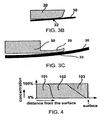
- Figure 3B schematically show a detail of figure 3A .
- Figure 3B shows the form of the edge of through-hole 21 in the base plate 20.
- the flexible plate contacts the base plate round contour 32.
- the size of the contact zone can be realized by giving the contour 32 of the through-hole 21 in the base plate a minimum radius, said radius resulting in a sufficiently large size of the contact zone.
- Figure 3C shows a preferred embodiment, where the through-hole takes the form of a through-hole with a lip.
- the proper choice of the rim of the through-hole and of the materials is determined by many factors, each of them showing certain advantages and disadvantages. However, for each of them the maximum pressure can be determined and thereby the curvature of the rim can be derived. Also the flexibility of the flexible plate 30 has to be taken into account, as this determines the position of the contour as well.
- the radius to be used for the rim is often in excess of 1 metre.
- a preferred method of forming a through-hole 21 with such a rim is by machining the through-hole with a lip 25 (the contour where the vacuum seal forms positioned on the lip) and then plastically deforming the lip into the required form with a rubber pad. By controlling the thickness of the lip and the compression of the rubber pad, a good control of the radius of the rim 25 is realized.
- a combination showing a low friction coefficient is a polished flexible plate of steel combined with a base plate showing a surface comprising a fluoropolymer such as PTFE.
- the entire base plate can be made of such a polymer, or it can be e.g. a polished metal plate coated by or impregnated with PTFE.
- a steel flexible plate is combined with a base plate showing a bronze surface coating, in which the bronze surface coating is impregnated with a fluoropolymer comprising PTFE.
- Figure 4 schematically shows the composition of such a base plate: the bulk 101 of the base plate is steel, with a layer 102 of bronze on its surface. This layer is porous, its porosity increasing when going to the surface. Impregnating this bronze layer with a fluoropolymer 103 thus results in an increase of the amount of the fluoropolymer near the surface, resulting in a pure or almost pure layer of the polymer 103 at the surface.
Landscapes
- Chemical & Material Sciences (AREA)
- Analytical Chemistry (AREA)
- Sliding-Contact Bearings (AREA)
- Sliding Valves (AREA)
- Analysing Materials By The Use Of Radiation (AREA)
- Bearings For Parts Moving Linearly (AREA)
- Sampling And Sample Adjustment (AREA)
- Magnetic Bearings And Hydrostatic Bearings (AREA)
Claims (14)
- Palier lisse pour utilisation avec un appareil comportant une chambre à vide (11), le palier lisse comportant :une plaque de base (20) en contact avec la chambre à vide (11) sur un côté, ladite plaque de base présentant un premier trou débouchant (21) en contact avec la chambre à vide (11),une deuxième plaque (30), un côté de la deuxième plaque étant en contact avec la plaque de base (20), ladite deuxième plaque présentant un deuxième trou débouchant (31),les faces de la plaque de base et de la deuxième plaque qui se font face étant suffisamment lisses pour former un joint hermétique non-élastomère,ladite plaque de base (20) et ladite deuxième plaque (30) pouvant glisser entre une première position relative dans laquelle le premier trou débouchant (21) et le deuxième trou débouchant (31) ne se chevauchent pas et une deuxième position relative dans laquelle le premier trou débouchant et le deuxième trou débouchant se chevauchent,caractérisé en ce quela deuxième plaque (30) est une plaque flexible,la face de la plaque flexible opposée à la plaque de base est prévue pour assurer l'étanchéité contre une ventouse (50), la ventouse étant prévue pour maintenir un échantillon (1),le premier trou débouchant (21) dans la plaque de base présente un pourtour faisant face à la plaque flexible (30) avec une courbure commandée, la courbure du pourtour étant formée de telle sorte que le joint hermétique entre la plaque de base et la plaque flexible se forme sur un contour prédéfini et que la pression de contact hertzienne est plus petite qu'une pression de contact maximum prédéfinie, la pression de contact maximum prédéterminée étant choisie pour minimiser la génération de particules.
- Palier lisse selon la revendication 1 dans lequel la pression de contact maximum prédéterminée est inférieure à la limite d'élasticité maximum obtenue à partir du critère de déformation de Von Mises ou du critère d'effort de cisaillement maximum de Tresca.
- Palier lisse selon l'une quelconque des revendications précédentes dans lequel la plaque flexible (30) est pressée contre la plaque de base (20) par un ou plusieurs éléments élastiques.
- Palier lisse selon l'une quelconque des revendications précédentes dans lequel au moins une des plaques (20, 30) présente une couche de surface avec une composition différente de la masse de la plaque, le coefficient de friction entre ladite couche de surface et l'autre plaque étant plus petit que le coefficient de friction entre la matière de ladite plaque et l'autre plaque.
- Palier lisse selon l'une quelconque des revendications précédentes dans lequel au moins une des plaques (20, 30) présente une couche de surface comportant du cuivre.
- Palier lisse selon l'une quelconque des revendications précédentes dans lequel au moins une des plaques (20, 30) présente une couche de surface comportant un polymère fluoré.
- Palier lisse selon la revendication 6 dans lequel le polymère fluoré est du PTFE.
- Palier lisse selon l'une quelconque des revendications 1 à 5 dans lequel au moins une des plaques (20, 30) est recouverte ou imprégnée d'une substance comportant un bisulfure de métal.
- Palier lisse selon la revendication 8 dans lequel le bisulfure de métal est un bisulfure de métal du groupe MoS2, WS2 et SeS2.
- Palier lisse selon l'une quelconque des revendications 1 à 5 dans lequel au moins une des plaques (20, 30) est recouverte ou imprégnée d'une graisse ou d'une huile.
- Appareil comportant un palier lisse selon l'une quelconque des revendications précédentes, ledit appareil comportant la chambre à vide (11).
- Appareil selon la revendication 11 dans lequel la chambre à vide (11) fait partie d'une colonne à particule optique (10).
- Appareil selon la revendication 12 dans lequel la colonne à particule optique (10) génère un faisceau focalisé d'ions et/ou d'électrons.
- Appareil selon la revendication 13 dans lequel l'appareil prend la forme d'un microscope à balayage électronique (SEM).
Applications Claiming Priority (2)
| Application Number | Priority Date | Filing Date | Title |
|---|---|---|---|
| US81162106P | 2006-06-07 | 2006-06-07 | |
| PCT/US2007/010006 WO2007145712A2 (fr) | 2006-06-07 | 2007-04-26 | Palier lisse pour une utilisation avec un appareil comprenant une chambre à vide |
Publications (2)
| Publication Number | Publication Date |
|---|---|
| EP2033206A2 EP2033206A2 (fr) | 2009-03-11 |
| EP2033206B1 true EP2033206B1 (fr) | 2011-06-08 |
Family
ID=40343642
Family Applications (1)
| Application Number | Title | Priority Date | Filing Date |
|---|---|---|---|
| EP07756002A Active EP2033206B1 (fr) | 2006-06-07 | 2007-04-26 | Palier lisse pour une utilisation avec un appareil comprenant une chambre à vide |
Country Status (5)
| Country | Link |
|---|---|
| US (1) | US8598524B2 (fr) |
| EP (1) | EP2033206B1 (fr) |
| JP (1) | JP5033873B2 (fr) |
| AT (1) | ATE512457T1 (fr) |
| WO (1) | WO2007145712A2 (fr) |
Families Citing this family (13)
| Publication number | Priority date | Publication date | Assignee | Title |
|---|---|---|---|---|
| EP1816668A2 (fr) | 2006-02-01 | 2007-08-08 | FEI Company | Dispositif optique à particules chargées à pression finale prédéterminée |
| JP5033873B2 (ja) | 2006-06-07 | 2012-09-26 | エフ イー アイ カンパニ | 真空チャンバを有する機器とともに使用されるスライダベアリング |
| CN101461026B (zh) | 2006-06-07 | 2012-01-18 | Fei公司 | 与包含真空室的装置一起使用的滑动轴承 |
| EP2220411B1 (fr) | 2007-12-11 | 2012-03-21 | Isentropic Limited | Vanne |
| EP2292953A1 (fr) | 2009-09-07 | 2011-03-09 | Fei Company | Joint pour vide poussé |
| FR2979684B1 (fr) * | 2011-09-07 | 2014-08-08 | Commissariat Energie Atomique | Dispositif de deplacement relatif de deux pieces sous pression differentielle |
| JP5989471B2 (ja) * | 2012-09-14 | 2016-09-07 | 日本発條株式会社 | 圧電素子供給方法 |
| US20150097485A1 (en) * | 2013-10-08 | 2015-04-09 | XEI Scientific Inc. | Method and apparatus for plasma ignition in high vacuum chambers |
| TWI674392B (zh) * | 2014-03-27 | 2019-10-11 | 日商荏原製作所股份有限公司 | 頂板開閉機構及檢查裝置 |
| NL2013432B1 (en) | 2014-09-05 | 2016-09-28 | Delmic B V | Compact inspection apparatus comprising a combination of a Scanning Electron Microscope and an Optical microscope. |
| CN108984933B (zh) * | 2018-07-25 | 2022-05-20 | 太原科技大学 | 弹流润滑条件下计算滚动轴承载荷和压力的边界元法 |
| KR102198707B1 (ko) | 2019-03-25 | 2021-01-05 | (주)코셈 | 착탈 가능한 컬럼을 구비하는 주사 전자 현미경 및, 이를 이용한 영상 획득 방법 |
| US12205807B2 (en) * | 2020-04-01 | 2025-01-21 | Mstm, Llc | Multi-mode ionization apparatus and uses thereof |
Family Cites Families (72)
| Publication number | Priority date | Publication date | Assignee | Title |
|---|---|---|---|---|
| US3602686A (en) | 1967-04-11 | 1971-08-31 | Westinghouse Electric Corp | Electron-beam apparatus and method of welding with this apparatus |
| US3981546A (en) * | 1969-09-29 | 1976-09-21 | Sperman Jacob H | Air bearing construction |
| US3971546A (en) * | 1975-04-21 | 1976-07-27 | Bruner A J | Animal crossing guard |
| JPS5523746Y2 (fr) * | 1976-02-05 | 1980-06-06 | ||
| US4165881A (en) * | 1976-07-15 | 1979-08-28 | Morgan Construction Company | Flexible seal and seal assembly |
| US4162391A (en) * | 1977-12-19 | 1979-07-24 | Sciaky Bros., Inc. | Sliding vacuum seal means |
| DE2819165A1 (de) * | 1978-05-02 | 1979-11-15 | Siemens Ag | Rasterelektronenmikroskop |
| EP0017472A1 (fr) * | 1979-04-06 | 1980-10-15 | Lintott Engineering Limited | Appareillage à vide comportant un dispositif de transfer thermique et procédé de fabrication de composants semi-conducteurs utilisant cet appareillage |
| US4229655A (en) * | 1979-05-23 | 1980-10-21 | Nova Associates, Inc. | Vacuum chamber for treating workpieces with beams |
| FR2499314A1 (fr) * | 1981-02-04 | 1982-08-06 | Centre Nat Rech Scient | Ensemble de microscope electronique a balayage a fonctionnement in situ |
| US4584479A (en) * | 1982-10-19 | 1986-04-22 | Varian Associates, Inc. | Envelope apparatus for localized vacuum processing |
| US4607167A (en) * | 1982-10-19 | 1986-08-19 | Varian Associates, Inc. | Charged particle beam lithography machine incorporating localized vacuum envelope |
| DE3332248A1 (de) | 1983-09-07 | 1985-03-21 | Lutz-Achim Dipl.-Ing. 7000 Stuttgart Gäng | System zum ableiten von probenaufladungen bei rasterelektronenmikroskopischen untersuchungen |
| US4705949A (en) | 1985-11-25 | 1987-11-10 | The United States Of America As Represented By The Secretary Of Commerce | Method and apparatus relating to specimen cells for scanning electron microscopes |
| DE3618283A1 (de) | 1986-05-30 | 1987-12-03 | Messer Griesheim Gmbh | Vorrichtung zum bearbeiten von werkstuecken mit einem elektronenstrahl |
| US4818838A (en) * | 1988-01-11 | 1989-04-04 | The Perkin-Elmer Corporation | Apparatus for preselecting and maintaining a fixed gap between a workpiece and a vacuum seal apparatus in particle beam lithography systems |
| JPH01296549A (ja) | 1988-05-25 | 1989-11-29 | Hitachi Ltd | 荷電粒子光学系 |
| US5103102A (en) * | 1989-02-24 | 1992-04-07 | Micrion Corporation | Localized vacuum apparatus and method |
| JPH03194838A (ja) | 1989-12-22 | 1991-08-26 | Sumitomo Metal Ind Ltd | 帯電防止方法及び該方法に使用する帯電防止装置 |
| US5254856A (en) * | 1990-06-20 | 1993-10-19 | Hitachi, Ltd. | Charged particle beam apparatus having particular electrostatic objective lens and vacuum pump systems |
| JPH04363849A (ja) | 1991-06-10 | 1992-12-16 | Mitsubishi Electric Corp | 電子ビーム装置 |
| US5396067A (en) * | 1992-06-11 | 1995-03-07 | Nikon Corporation | Scan type electron microscope |
| JP2851213B2 (ja) * | 1992-09-28 | 1999-01-27 | 株式会社東芝 | 走査電子顕微鏡 |
| JPH06139984A (ja) | 1992-10-23 | 1994-05-20 | Hitachi Ltd | 電子顕微鏡の真空リーク機構 |
| JP3422045B2 (ja) * | 1993-06-21 | 2003-06-30 | 株式会社日立製作所 | 組成及び格子歪測定用電子顕微鏡及びその観察方法 |
| JP3310136B2 (ja) * | 1994-09-17 | 2002-07-29 | 株式会社東芝 | 荷電ビーム装置 |
| FR2747112B1 (fr) | 1996-04-03 | 1998-05-07 | Commissariat Energie Atomique | Dispositif de transport d'objets plats et procede de transfert de ces objets entre ledit dispositif et une machine de traitement |
| US5869833A (en) * | 1997-01-16 | 1999-02-09 | Kla-Tencor Corporation | Electron beam dose control for scanning electron microscopy and critical dimension measurement instruments |
| SG74599A1 (en) | 1997-09-27 | 2000-08-22 | Inst Of Material Res & Enginee | Portable high resolution scanning electron microscope column using permanent magnet electron lenses |
| US5989444A (en) * | 1998-02-13 | 1999-11-23 | Zywno; Marek | Fluid bearings and vacuum chucks and methods for producing same |
| EP0969494A1 (fr) | 1998-07-03 | 2000-01-05 | ICT Integrated Circuit Testing Gesellschaft für Halbleiterprüftechnik mbH | Appareil et procédé pour examiner un échantillon à l'aide d'un faisceau de particules chargées |
| US6476913B1 (en) * | 1998-11-30 | 2002-11-05 | Hitachi, Ltd. | Inspection method, apparatus and system for circuit pattern |
| TWI242111B (en) * | 1999-04-19 | 2005-10-21 | Asml Netherlands Bv | Gas bearings for use in vacuum chambers and their application in lithographic projection apparatus |
| TWI233535B (en) * | 1999-04-19 | 2005-06-01 | Asml Netherlands Bv | Motion feed-through into a vacuum chamber and its application in lithographic projection apparatuses |
| EP1122761B1 (fr) | 2000-02-01 | 2004-05-26 | ICT Integrated Circuit Testing Gesellschaft für Halbleiterprüftechnik mbH | Colonne optique pour dispositif à faisceau de particules chargées |
| US6515288B1 (en) * | 2000-03-16 | 2003-02-04 | Applied Materials, Inc. | Vacuum bearing structure and a method of supporting a movable member |
| US6559457B1 (en) * | 2000-03-23 | 2003-05-06 | Advanced Micro Devices, Inc. | System and method for facilitating detection of defects on a wafer |
| US6582251B1 (en) * | 2000-04-28 | 2003-06-24 | Greene, Tweed Of Delaware, Inc. | Hermetic electrical connector and method of making the same |
| JP3619132B2 (ja) * | 2000-08-25 | 2005-02-09 | 株式会社日立製作所 | 電子顕微鏡 |
| US6507147B1 (en) * | 2000-08-31 | 2003-01-14 | Intevac, Inc. | Unitary vacuum tube incorporating high voltage isolation |
| US6683316B2 (en) * | 2001-08-01 | 2004-01-27 | Aspex, Llc | Apparatus for correlating an optical image and a SEM image and method of use thereof |
| JP2003086355A (ja) * | 2001-09-05 | 2003-03-20 | Kiko Kenji Kagi Kofun Yugenkoshi | 有機el素子の封止構造並びに封止方法及び封止装置 |
| JP3886777B2 (ja) * | 2001-11-02 | 2007-02-28 | 日本電子株式会社 | 電子線照射装置および方法 |
| US6710354B1 (en) * | 2001-12-11 | 2004-03-23 | Kla-Tencor Corporation | Scanning electron microscope architecture and related material handling system |
| JP4014916B2 (ja) * | 2002-04-11 | 2007-11-28 | 株式会社キーエンス | 電子顕微鏡、電子顕微鏡の操作方法、電子顕微鏡操作プログラムおよびコンピュータで読み取り可能な記録媒体 |
| US6891170B1 (en) * | 2002-06-17 | 2005-05-10 | Zyvex Corporation | Modular manipulation system for manipulating a sample under study with a microscope |
| JP2004031207A (ja) | 2002-06-27 | 2004-01-29 | Canon Inc | 電子線照射装置および走査型電子顕微鏡装置 |
| US6667475B1 (en) * | 2003-01-08 | 2003-12-23 | Applied Materials, Inc. | Method and apparatus for cleaning an analytical instrument while operating the analytical instrument |
| JP4373104B2 (ja) | 2003-02-18 | 2009-11-25 | 株式会社荏原製作所 | 荷電粒子ビーム装置 |
| NL1022886C2 (nl) * | 2003-03-10 | 2004-09-14 | Fei Co | Deeltjes optische inrichting voor het bestralen van een object. |
| JP4211473B2 (ja) | 2003-04-25 | 2009-01-21 | ソニー株式会社 | 電子顕微鏡 |
| JP2004349515A (ja) * | 2003-05-23 | 2004-12-09 | Hitachi High-Technologies Corp | Sem式外観検査装置,レビュー装置、およびアライメント座標設定方法 |
| US6897443B2 (en) * | 2003-06-02 | 2005-05-24 | Harald Gross | Portable scanning electron microscope |
| US7060990B2 (en) * | 2003-06-16 | 2006-06-13 | Sumitomo Heavy Industries, Ltd. | Stage base, substrate processing apparatus, and maintenance method for stage |
| US7100925B2 (en) * | 2003-07-31 | 2006-09-05 | Perkin Elmer, Inc. | Pressure energized metallic seal |
| KR100592242B1 (ko) * | 2003-08-12 | 2006-06-21 | 삼성에스디아이 주식회사 | 캐리어 및 이를 구비하는 분석장치 |
| JP4063201B2 (ja) | 2003-11-18 | 2008-03-19 | ソニー株式会社 | 電子ビーム照射装置 |
| US7043848B2 (en) * | 2003-11-26 | 2006-05-16 | The Micromanipulator Company | Method and apparatus for maintaining accurate positioning between a probe and a DUT |
| JP2005203123A (ja) | 2004-01-13 | 2005-07-28 | Sony Corp | 荷電粒子ビーム装置。 |
| JP4528014B2 (ja) * | 2004-04-05 | 2010-08-18 | 株式会社日立ハイテクノロジーズ | 試料検査方法 |
| JP4559137B2 (ja) * | 2004-06-30 | 2010-10-06 | キヤノン株式会社 | 真空機器の製造装置及び製造方法 |
| NL1026547C2 (nl) * | 2004-07-01 | 2006-01-03 | Fei Co | Apparaat voor het evacueren van een sample. |
| US20060249917A1 (en) * | 2005-04-07 | 2006-11-09 | Saint-Gobain Performance Plastics Corporation | Composite sealing device |
| US20070011300A1 (en) | 2005-07-11 | 2007-01-11 | Hollebeek Robert J | Monitoring method and system for monitoring operation of resources |
| US7301157B2 (en) | 2005-09-28 | 2007-11-27 | Fei Company | Cluster tool for microscopic processing of samples |
| NL1030295C2 (nl) * | 2005-10-28 | 2007-05-03 | Fei Co | Hermetisch afgesloten behuizing met elektrische doorvoer. |
| EP1816668A2 (fr) * | 2006-02-01 | 2007-08-08 | FEI Company | Dispositif optique à particules chargées à pression finale prédéterminée |
| EP1863066A1 (fr) * | 2006-05-29 | 2007-12-05 | FEI Company | Support d'échantillon et porte-échantillon |
| CN101461026B (zh) | 2006-06-07 | 2012-01-18 | Fei公司 | 与包含真空室的装置一起使用的滑动轴承 |
| JP5033873B2 (ja) | 2006-06-07 | 2012-09-26 | エフ イー アイ カンパニ | 真空チャンバを有する機器とともに使用されるスライダベアリング |
| EP2105944A1 (fr) * | 2008-03-28 | 2009-09-30 | FEI Company | "Cellule environnementale" pour appareil optique à particules chargées |
| US8087309B2 (en) * | 2009-05-22 | 2012-01-03 | Sion Power Corporation | Hermetic sample holder and method for performing microanalysis under controlled atmosphere environment |
-
2007
- 2007-04-26 JP JP2009514260A patent/JP5033873B2/ja active Active
- 2007-04-26 US US12/303,715 patent/US8598524B2/en active Active
- 2007-04-26 AT AT07756002T patent/ATE512457T1/de not_active IP Right Cessation
- 2007-04-26 EP EP07756002A patent/EP2033206B1/fr active Active
- 2007-04-26 WO PCT/US2007/010006 patent/WO2007145712A2/fr not_active Ceased
Also Published As
| Publication number | Publication date |
|---|---|
| US8598524B2 (en) | 2013-12-03 |
| EP2033206A2 (fr) | 2009-03-11 |
| WO2007145712A2 (fr) | 2007-12-21 |
| WO2007145712A3 (fr) | 2008-04-17 |
| US20100276592A1 (en) | 2010-11-04 |
| ATE512457T1 (de) | 2011-06-15 |
| JP5033873B2 (ja) | 2012-09-26 |
| JP2009540499A (ja) | 2009-11-19 |
Similar Documents
| Publication | Publication Date | Title |
|---|---|---|
| EP2033206B1 (fr) | Palier lisse pour une utilisation avec un appareil comprenant une chambre à vide | |
| CN101461026B (zh) | 与包含真空室的装置一起使用的滑动轴承 | |
| JP6037741B2 (ja) | 移動型真空溶接装置 | |
| JP5746056B2 (ja) | 多重エネルギHe+、He2+イオンを用いてエラストマー部品の表面を処理する処理方法 | |
| JP5046365B2 (ja) | サンプルを顕微処理するためのクラスタ器具 | |
| JP5005192B2 (ja) | サンプルを真空排気するための装置 | |
| US20150213995A1 (en) | High-voltage energy-dispersive spectroscopy using a low-voltage scanning electron microscope | |
| US9000397B1 (en) | Specimen holder for observing top section of specimen and method for controlling the same | |
| Nevshupa et al. | Ultrahigh vacuum system for advanced tribology studies: Design principles and applications | |
| EP1830385A1 (fr) | Appareil à faisceau d'ions et procédé pour les aligner | |
| CN206332001U (zh) | 一种真空气氛处理装置及样品观测系统 | |
| KR102552225B1 (ko) | 주사 전자 현미경 | |
| US20250029808A1 (en) | Valves for charged particle beam microscope, valve member and charged particle beam microscope | |
| CN119314844B (zh) | 带电粒子束成像装置 | |
| EP2592314A1 (fr) | Dispositif de faisceau à particules chargées, soupape sous vide pour celui-ci et fonctionnement correspondant | |
| EP1169726A1 (fr) | Support d'objet pour un appareil optique a particules | |
| US20090212660A1 (en) | Ultrasonic motor and method for manufacturing ultrasonic motor | |
| GB2063389A (en) | Seal | |
| WO2003054909A1 (fr) | Microscope electronique a balayage et son procede d'utilisation | |
| JP2012041432A (ja) | 表面改質方法及び樹脂製部材 | |
| JP2020180925A (ja) | 摩擦の観察方法及び観察装置 | |
| Kelly et al. | Using Electron Spectroscopy for Chemical Analysis (ESCA) in Failure Analysis: Some Recent Developments | |
| KR20090047952A (ko) | 주사 전자 현미경 | |
| Yoshimura | Accidents and Information, Instructing Us to Improve the Vacuum Systems of JEMs |
Legal Events
| Date | Code | Title | Description |
|---|---|---|---|
| PUAI | Public reference made under article 153(3) epc to a published international application that has entered the european phase |
Free format text: ORIGINAL CODE: 0009012 |
|
| 17P | Request for examination filed |
Effective date: 20081205 |
|
| AK | Designated contracting states |
Kind code of ref document: A2 Designated state(s): AT BE BG CH CY CZ DE DK EE ES FI FR GB GR HU IE IS IT LI LT LU LV MC MT NL PL PT RO SE SI SK TR |
|
| AX | Request for extension of the european patent |
Extension state: AL BA HR MK RS |
|
| DAX | Request for extension of the european patent (deleted) | ||
| GRAP | Despatch of communication of intention to grant a patent |
Free format text: ORIGINAL CODE: EPIDOSNIGR1 |
|
| GRAS | Grant fee paid |
Free format text: ORIGINAL CODE: EPIDOSNIGR3 |
|
| GRAA | (expected) grant |
Free format text: ORIGINAL CODE: 0009210 |
|
| AK | Designated contracting states |
Kind code of ref document: B1 Designated state(s): AT BE BG CH CY CZ DE DK EE ES FI FR GB GR HU IE IS IT LI LT LU LV MC MT NL PL PT RO SE SI SK TR |
|
| REG | Reference to a national code |
Ref country code: GB Ref legal event code: FG4D |
|
| REG | Reference to a national code |
Ref country code: CH Ref legal event code: EP |
|
| REG | Reference to a national code |
Ref country code: IE Ref legal event code: FG4D |
|
| REG | Reference to a national code |
Ref country code: DE Ref legal event code: R096 Ref document number: 602007015101 Country of ref document: DE Effective date: 20110721 |
|
| REG | Reference to a national code |
Ref country code: NL Ref legal event code: VDEP Effective date: 20110608 |
|
| PG25 | Lapsed in a contracting state [announced via postgrant information from national office to epo] |
Ref country code: LT Free format text: LAPSE BECAUSE OF FAILURE TO SUBMIT A TRANSLATION OF THE DESCRIPTION OR TO PAY THE FEE WITHIN THE PRESCRIBED TIME-LIMIT Effective date: 20110608 Ref country code: SE Free format text: LAPSE BECAUSE OF FAILURE TO SUBMIT A TRANSLATION OF THE DESCRIPTION OR TO PAY THE FEE WITHIN THE PRESCRIBED TIME-LIMIT Effective date: 20110608 |
|
| PG25 | Lapsed in a contracting state [announced via postgrant information from national office to epo] |
Ref country code: AT Free format text: LAPSE BECAUSE OF FAILURE TO SUBMIT A TRANSLATION OF THE DESCRIPTION OR TO PAY THE FEE WITHIN THE PRESCRIBED TIME-LIMIT Effective date: 20110608 Ref country code: SI Free format text: LAPSE BECAUSE OF FAILURE TO SUBMIT A TRANSLATION OF THE DESCRIPTION OR TO PAY THE FEE WITHIN THE PRESCRIBED TIME-LIMIT Effective date: 20110608 Ref country code: ES Free format text: LAPSE BECAUSE OF FAILURE TO SUBMIT A TRANSLATION OF THE DESCRIPTION OR TO PAY THE FEE WITHIN THE PRESCRIBED TIME-LIMIT Effective date: 20110919 Ref country code: GR Free format text: LAPSE BECAUSE OF FAILURE TO SUBMIT A TRANSLATION OF THE DESCRIPTION OR TO PAY THE FEE WITHIN THE PRESCRIBED TIME-LIMIT Effective date: 20110909 Ref country code: LV Free format text: LAPSE BECAUSE OF FAILURE TO SUBMIT A TRANSLATION OF THE DESCRIPTION OR TO PAY THE FEE WITHIN THE PRESCRIBED TIME-LIMIT Effective date: 20110608 Ref country code: FI Free format text: LAPSE BECAUSE OF FAILURE TO SUBMIT A TRANSLATION OF THE DESCRIPTION OR TO PAY THE FEE WITHIN THE PRESCRIBED TIME-LIMIT Effective date: 20110608 Ref country code: CY Free format text: LAPSE BECAUSE OF FAILURE TO SUBMIT A TRANSLATION OF THE DESCRIPTION OR TO PAY THE FEE WITHIN THE PRESCRIBED TIME-LIMIT Effective date: 20110608 |
|
| PG25 | Lapsed in a contracting state [announced via postgrant information from national office to epo] |
Ref country code: NL Free format text: LAPSE BECAUSE OF FAILURE TO SUBMIT A TRANSLATION OF THE DESCRIPTION OR TO PAY THE FEE WITHIN THE PRESCRIBED TIME-LIMIT Effective date: 20110608 Ref country code: BE Free format text: LAPSE BECAUSE OF FAILURE TO SUBMIT A TRANSLATION OF THE DESCRIPTION OR TO PAY THE FEE WITHIN THE PRESCRIBED TIME-LIMIT Effective date: 20110608 |
|
| PG25 | Lapsed in a contracting state [announced via postgrant information from national office to epo] |
Ref country code: EE Free format text: LAPSE BECAUSE OF FAILURE TO SUBMIT A TRANSLATION OF THE DESCRIPTION OR TO PAY THE FEE WITHIN THE PRESCRIBED TIME-LIMIT Effective date: 20110608 Ref country code: CZ Free format text: LAPSE BECAUSE OF FAILURE TO SUBMIT A TRANSLATION OF THE DESCRIPTION OR TO PAY THE FEE WITHIN THE PRESCRIBED TIME-LIMIT Effective date: 20110608 Ref country code: PT Free format text: LAPSE BECAUSE OF FAILURE TO SUBMIT A TRANSLATION OF THE DESCRIPTION OR TO PAY THE FEE WITHIN THE PRESCRIBED TIME-LIMIT Effective date: 20111010 Ref country code: IS Free format text: LAPSE BECAUSE OF FAILURE TO SUBMIT A TRANSLATION OF THE DESCRIPTION OR TO PAY THE FEE WITHIN THE PRESCRIBED TIME-LIMIT Effective date: 20111008 |
|
| PG25 | Lapsed in a contracting state [announced via postgrant information from national office to epo] |
Ref country code: PL Free format text: LAPSE BECAUSE OF FAILURE TO SUBMIT A TRANSLATION OF THE DESCRIPTION OR TO PAY THE FEE WITHIN THE PRESCRIBED TIME-LIMIT Effective date: 20110608 Ref country code: RO Free format text: LAPSE BECAUSE OF FAILURE TO SUBMIT A TRANSLATION OF THE DESCRIPTION OR TO PAY THE FEE WITHIN THE PRESCRIBED TIME-LIMIT Effective date: 20110608 Ref country code: SK Free format text: LAPSE BECAUSE OF FAILURE TO SUBMIT A TRANSLATION OF THE DESCRIPTION OR TO PAY THE FEE WITHIN THE PRESCRIBED TIME-LIMIT Effective date: 20110608 |
|
| PLBE | No opposition filed within time limit |
Free format text: ORIGINAL CODE: 0009261 |
|
| STAA | Information on the status of an ep patent application or granted ep patent |
Free format text: STATUS: NO OPPOSITION FILED WITHIN TIME LIMIT |
|
| 26N | No opposition filed |
Effective date: 20120309 |
|
| PG25 | Lapsed in a contracting state [announced via postgrant information from national office to epo] |
Ref country code: IT Free format text: LAPSE BECAUSE OF FAILURE TO SUBMIT A TRANSLATION OF THE DESCRIPTION OR TO PAY THE FEE WITHIN THE PRESCRIBED TIME-LIMIT Effective date: 20110608 |
|
| PG25 | Lapsed in a contracting state [announced via postgrant information from national office to epo] |
Ref country code: DK Free format text: LAPSE BECAUSE OF FAILURE TO SUBMIT A TRANSLATION OF THE DESCRIPTION OR TO PAY THE FEE WITHIN THE PRESCRIBED TIME-LIMIT Effective date: 20110608 |
|
| REG | Reference to a national code |
Ref country code: DE Ref legal event code: R097 Ref document number: 602007015101 Country of ref document: DE Effective date: 20120309 |
|
| PG25 | Lapsed in a contracting state [announced via postgrant information from national office to epo] |
Ref country code: MC Free format text: LAPSE BECAUSE OF NON-PAYMENT OF DUE FEES Effective date: 20120430 |
|
| REG | Reference to a national code |
Ref country code: CH Ref legal event code: PL |
|
| REG | Reference to a national code |
Ref country code: IE Ref legal event code: MM4A |
|
| PG25 | Lapsed in a contracting state [announced via postgrant information from national office to epo] |
Ref country code: CH Free format text: LAPSE BECAUSE OF NON-PAYMENT OF DUE FEES Effective date: 20120430 Ref country code: LI Free format text: LAPSE BECAUSE OF NON-PAYMENT OF DUE FEES Effective date: 20120430 Ref country code: IE Free format text: LAPSE BECAUSE OF NON-PAYMENT OF DUE FEES Effective date: 20120426 |
|
| PG25 | Lapsed in a contracting state [announced via postgrant information from national office to epo] |
Ref country code: BG Free format text: LAPSE BECAUSE OF FAILURE TO SUBMIT A TRANSLATION OF THE DESCRIPTION OR TO PAY THE FEE WITHIN THE PRESCRIBED TIME-LIMIT Effective date: 20110908 |
|
| PG25 | Lapsed in a contracting state [announced via postgrant information from national office to epo] |
Ref country code: MT Free format text: LAPSE BECAUSE OF FAILURE TO SUBMIT A TRANSLATION OF THE DESCRIPTION OR TO PAY THE FEE WITHIN THE PRESCRIBED TIME-LIMIT Effective date: 20110608 |
|
| PG25 | Lapsed in a contracting state [announced via postgrant information from national office to epo] |
Ref country code: TR Free format text: LAPSE BECAUSE OF FAILURE TO SUBMIT A TRANSLATION OF THE DESCRIPTION OR TO PAY THE FEE WITHIN THE PRESCRIBED TIME-LIMIT Effective date: 20110608 |
|
| PG25 | Lapsed in a contracting state [announced via postgrant information from national office to epo] |
Ref country code: LU Free format text: LAPSE BECAUSE OF NON-PAYMENT OF DUE FEES Effective date: 20120426 |
|
| PG25 | Lapsed in a contracting state [announced via postgrant information from national office to epo] |
Ref country code: HU Free format text: LAPSE BECAUSE OF FAILURE TO SUBMIT A TRANSLATION OF THE DESCRIPTION OR TO PAY THE FEE WITHIN THE PRESCRIBED TIME-LIMIT Effective date: 20070426 |
|
| REG | Reference to a national code |
Ref country code: FR Ref legal event code: PLFP Year of fee payment: 10 |
|
| REG | Reference to a national code |
Ref country code: FR Ref legal event code: PLFP Year of fee payment: 11 |
|
| REG | Reference to a national code |
Ref country code: FR Ref legal event code: PLFP Year of fee payment: 12 |
|
| P01 | Opt-out of the competence of the unified patent court (upc) registered |
Effective date: 20230524 |
|
| PGFP | Annual fee paid to national office [announced via postgrant information from national office to epo] |
Ref country code: DE Payment date: 20250314 Year of fee payment: 19 |
|
| PGFP | Annual fee paid to national office [announced via postgrant information from national office to epo] |
Ref country code: FR Payment date: 20250403 Year of fee payment: 19 |
|
| PGFP | Annual fee paid to national office [announced via postgrant information from national office to epo] |
Ref country code: GB Payment date: 20260311 Year of fee payment: 20 |