EP2033283B1 - Zündkerze mit kleinem durchmesser und grosser reichweite - Google Patents
Zündkerze mit kleinem durchmesser und grosser reichweite Download PDFInfo
- Publication number
- EP2033283B1 EP2033283B1 EP07784479.3A EP07784479A EP2033283B1 EP 2033283 B1 EP2033283 B1 EP 2033283B1 EP 07784479 A EP07784479 A EP 07784479A EP 2033283 B1 EP2033283 B1 EP 2033283B1
- Authority
- EP
- European Patent Office
- Prior art keywords
- insulator
- spark plug
- shell
- tip
- transition
- Prior art date
- Legal status (The legal status is an assumption and is not a legal conclusion. Google has not performed a legal analysis and makes no representation as to the accuracy of the status listed.)
- Revoked
Links
Images


Classifications
-
- H—ELECTRICITY
- H01—ELECTRIC ELEMENTS
- H01T—SPARK GAPS; OVERVOLTAGE ARRESTERS USING SPARK GAPS; SPARKING PLUGS; CORONA DEVICES; GENERATING IONS TO BE INTRODUCED INTO NON-ENCLOSED GASES
- H01T13/00—Sparking plugs
- H01T13/20—Sparking plugs characterised by features of the electrodes or insulation
- H01T13/39—Selection of materials for electrodes
-
- H—ELECTRICITY
- H01—ELECTRIC ELEMENTS
- H01T—SPARK GAPS; OVERVOLTAGE ARRESTERS USING SPARK GAPS; SPARKING PLUGS; CORONA DEVICES; GENERATING IONS TO BE INTRODUCED INTO NON-ENCLOSED GASES
- H01T13/00—Sparking plugs
- H01T13/20—Sparking plugs characterised by features of the electrodes or insulation
Definitions
- the invention relates to a spark plug for an internal combustion engine, furnace, or the like and, more particularly, toward a spark plug having improved mechanical and dielectric strength.
- a spark plug is a device that extends into the combustion chamber of an internal combustion engine, furnace or the like and produces a spark to ignite a mixture of air and fuel.
- Recent developments in engine technology are driving toward smaller engine displacement. At the same time, intake and exhaust valves are being enlarged for improved efficiency. The physical space reserved for the spark plug is being encroached upon by these changes. Combustion efficiencies are also dictating an increase in voltage requirements for the ignition system. These and other factors are urging the physical dimensions of a spark plug to ever-smaller scales, while demanding greater performance from the spark plug.
- Current industry demands call for high-performing spark plugs in the 10-12 mm range, with the expectation that these sizes will be further shrunk in the future.
- Dielectric strength is generally defined as the maximum electric field which can be applied to the material without causing breakdown or electrical puncture. Thin cross-sections of ceramic insulator can therefore result in dielectric puncture between the charged center electrode and the grounded shell.
- US 6 310 430 B1 discloses a spark plug for attachment to a cylinder head, including a metallic shell including a tip-end side having an open tip end and a tail-end side having an open tail end.
- the metallic shell has an attachment screw portion peripherally formed at the tip-end side thereof.
- the spark plug also includes a ground electrode attached onto the tip-end side of the metallic shell, and an insulator including an axial through-hole formed therein and a tail end portion having a tail end. The insulator is disposed within the metallic shell such that the tail end portion of the insulator substantially projects from the tail end of the metallic shell.
- a center electrode has a tip end and is disposed within the through-hole and facing the ground electrode to define a spark discharge gap therebetween, and a metallic terminal has a tail end and is disposed within the through-hole of the insulator such that the tail end of the metallic terminal is set back from the tail end of the insulator into the through-hole.
- the metallic terminal is electrically connected with the center electrode.
- the metallic terminal and the tail end of the metallic shell are separated with a distance for preventing an electrical discharge therebetween, and wherein, when A represents a distance between the tail end of the insulator and the tail end of the metallic terminal disposed within the through-hole, and B represents a length of the tail end portion of the insulator projecting from the tail end of the metallic shell along the axial direction of the through-hole of the insulator, a length of (A+B) is at least 20 mm.
- a spark plug according to claim 1 for a spark-ignited internal combustion engine comprises an elongated ceramic insulator having an upper terminal end, a lower nose end, and a central passage extending longitudinally between the terminal and nose ends.
- the insulator includes an exterior surface presenting a generally circular large shoulder proximate the terminal end and a generally circular small shoulder proximate the nose end.
- the large shoulder has a diameter greater than the diameter of the small shoulder.
- a conductive shell surrounds at least a portion of the insulator.
- the shell includes at least one ground electrode.
- a conductive center electrode is disposed in the central passage and has an exposed sparking tip proximate the ground electrode.
- the lower nose end of the insulator has a maximum outer diameter d(base) measured adjacent the small shoulder and a minimum outer diameter d(tip) measured adjacent the sparking tip of the center electrode.
- the shell includes an inner bore diameter ID(shell) surrounding the nose end of the insulator, establishing a spatial relationship according to the formula: 0.05 ⁇ d base + d tip 2 ⁇ ID shell ⁇ 0.7
- a spark plug manufactured according to these dimensional relationships substantially enhances the spark plug performance and is particularly suited for applications in which miniaturized spark plugs must be used in current engine designs due to the competition for space in the combustion area.
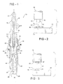
- the spark plug 10 includes a tubular ceramic insulator, generally indicated at 12, which is preferably made from aluminum oxide or other suitable material having a specified dielectric strength, high mechanical strength, high thermal conductivity, and excellent resistance to heat shock.
- the insulator 12 may be molded dry under extreme pressure and then kiln-fired to vitrification at high temperature.
- the insulator 12 has an outer surface which may include a partially exposed upper mast portion 14 to which a rubber spark plug boot (not shown) surrounds and grips to maintain a connection with the ignition system.
- the exposed mast portion 14 may include a series of ribs 16 to provide added protection against spark or secondary voltage flash-over and to improve grip with the rubber spark plug boot, or may be smooth as in Figure 9 .
- the insulator 12 is of generally tubular construction, including a central passage 18, extending longitudinally between an upper terminal end 20 and a lower nose end 22.
- the central passage 18 is of varying cross-sectional area, generally greatest at or adjacent the terminal end 20 and smallest at or adjacent the nose end 22.
- An electrically conductive, preferably metallic, shell is generally indicated at 24.
- the shell 24 surrounds the lower regions of the insulator 12 and includes at least one ground electrode 26. While the ground electrode 26 is depicted in the traditional single L-shaped style, it will be appreciated that multiple ground electrodes of straight or bent configuration can be substituted depending upon the intended application for the spark plug 10.
- the shell 24 is generally tubular in its body section and includes an internal lower compression flange 28 adapted to bear in pressing contact against a small lower shoulder 68 of the insulator 12.
- the shell 24 further includes an upper compression flange 30 which is crimped or formed over during the assembly operation to bear in pressing contact against a large upper shoulder 66 of the insulator 12.
- a buckle zone 32 collapses under the influence of an overwhelming compressive force during or subsequent to the deformation of the upper compression flange 72 to hold the shell 24 in a fixed position with respect to the insulator 12.
- Gaskets, cement, or other sealing compounds can be interposed between the insulator 12 and shell 24 to perfect a gas-tight seal and to improve the structural integrity of the assembled spark plug 10.
- the shell 24 is provided with a tool receiving hexagon 34 for removal and installation purposes.
- the hex size complies with industry standards for the related application. Of course, some applications may call for a tool receiving interface other than hexagon, such as is known in racing spark plug applications and in other environments.
- a threaded section 36 is formed at the lower portion of the metallic shell 24, immediately below a seat 38.
- the seat 38 may be paired with a gasket 39 to provide a suitable interface against which the spark plug 10 seats in the cylinder head.
- the seat 38 may be designed with a taper to provide a self-sealing installation in a cylinder head designed for this style of spark plug.
- An electrically conductive terminal stud 40 is partially disposed in the central passage 18 of the insulator 12 and extends longitudinally from an exposed top post to a bottom end embedded part way down the central passage 18.
- the top post connects to an ignition wire (not shown) and receives timed discharges of high voltage electricity required to fire the spark plug 10.
- the bottom end of the terminal stud 40 is embedded within a conductive glass seal 42, forming the top layer of a composite suppressor-seal pack.
- the conductive glass seal 42 functions to seal the bottom end of the terminal stud 40 to a resistor layer 44.
- This resistor layer 44 which comprises the center layer of the 3-tier suppressor-seal pack, can be made from any suitable composition known to reduce electromagnetic interference ("EMI").
- EMI electromagnetic interference
- resistor layers 44 may be designed to function as a more traditional resistor-suppressor or, in the alternative, as an inductive-suppressor.
- a conductive center electrode 48 is partially disposed in the central passage 18 and extends longitudinally from its head encased in the lower glass seal layer 46 to its exposed sparking end 50 proximate the ground electrode 26.
- the head seats in a necked-down section of the central passage 18.
- the suppressor-seal pack electrically interconnects the terminal stud 40 and the center electrode 48, while simultaneously sealing the central passage 18 from combustion gas leakage and also suppressing radio frequency noise emissions from the spark plug 10.
- the suppressor-sealed pack may be substituted with other passive or active features depending upon the requirements of an intended application.
- the center electrode 48 is preferably a one-piece structure extending continuously and uninterrupted between its head and its sparking end 50. However, other design arrangements may be used.
- a second metallic sparking tip 52 is located at the sparking end 50 of the center electrode 48. (To avoid any confusion, it is noted that a "first" metallic sparking tip will be introduced and described subsequently in connection with the ground electrode 26.)
- the second metallic sparking tip 52 provides a sparking surface for the emission of electrons across a spark gap 54.
- the second metallic sparking tip 52 for the center electrode 48 can be made according to any of the known techniques, including the loose piece formation and subsequent detachment of a wire-like or rivet-like construction made from any of the known precious metal or high performance alloys including, but not limited to, platinum, tungsten, rhodium, yttrium, iridium, and alloys thereof.
- Additional alloying elements may include, but are not limited to, nickel, chromium, iron, carbon, manganese, silicon, copper, aluminum, cobalt, rhenium, and the like. In fact, any material that provides good erosion and corrosion performance in the combustion environment may be suitable for use in the material composition of the second metallic sparking tip 52.
- the ground electrode 26 extends from an anchored end adjacent the shell 24 to a distal end adjacent the sparking gap 54.
- the ground electrode 26 may be of the typical rectangular cross-section, including an iron-based alloy jacket surrounding a copper core.
- a (first) metallic sparking tip is attached to the distal end of the ground electrode 26, opposing the sparking end 50 of the center electrode 48. I.e., the metallic sparking tip 56 is located directly across the spark gap 54.
- the metallic sparking tip 56 is intentionally shaped with a rimmed, hemispherical configuration such that it presents a convex dome 58 surrounded by a rim 60.
- the shape of the metallic sparking tip 56 can be likened to a fried egg, with the convex dome portion 58 representing the yolk of the analogous egg and the rim portion 60 representing the egg white.
- the rim 60 has a generally annular configuration, although non-annular configurations are also possible.
- the convex dome portion 58 and rim 60 are generally aligned with one another along an imaginary central axis intersecting the middle of the spark gap 54.
- the (first) metallic sparking tip 56 for the ground electrode 26 can be made according to any of the known techniques, including the loose piece formation into a button-like construction made from any of the known precious metal or high performance alloys including, but not limited to, platinum, tungsten, rhodium, yttrium, iridium, and alloys thereof. Additional alloying elements may include, but are not limited to, nickel, chromium, iron, carbon, manganese, silicon, copper, aluminum, cobalt, rhenium, and alike. In fact, any material that provides good erosion and corrosion performance in the combustion environment may be suitable for use in the material composition of the metallic sparking tip 56.
- Figure 3 represents an alternative embodiment of the invention, wherein the center electrode 48 is fitted with a second metallic sparking tip 52' having a rimmed hemispherical configuration substantially similar to that of the (first) metallic sparking tip 56 attached to the ground electrode 26.
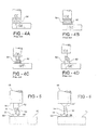
- FIGs 4A-D depict various prior art configurations for the spark gap 54 between ground and center electrodes.
- the ground electrode is represented by the letters "GE”
- the center electrode is represented by the letters "CE.”
- Figure 4A illustrates a typical spark gap 54 configuration, wherein neither the center electrode CE nor ground electrode GE are fitted with metallic sparking tips.
- electrical potential carried through the center electrode CE arcs through a "zone" of the spark gap 54 to the base material of the ground electrode, which typically comprises a durable, nickel based alloy frequently cored with copper for thermal transmission purposes.
- all electrical arcing from the center electrode CE to the ground electrode GE occurs in the spark gap 54.
- FIGS 4B-D represent various prior art configurations where the ground electrode GE is fitted with a metallic sparking tip of either wide or narrow relative construction.
- An opposing metallic sparking tip on the center electrode CE may be matched or mismatched in terms of its dimensional attributes to the metallic sparking tip on the ground electrode GE.
- electrical arcing it is common for electrical arcing to overshoot the precious metal pad of the sparking tip and directly land on the base material of the ground electrode GE. This is illustrated by a rogue electrical arc 62.
- Rogue arcs 62 are common in the combustion environment, and result in inconsistent combustion with a measurable drop in combustion efficiency. As a result of this cycle-to-cycle variation in the ignition event, an automobile driver may feel the engine is running rough and/or its performance is perceived as inconsistent. Accordingly, rogue arcs 62 are highly undesirable.
- Figures 5 and 6 illustrate the rimmed hemispherical metallic sparking tip 56 fitted to the ground electrode 26.
- the second metallic sparking tip 52 is of the conventional or modified (52') design, it is illustrated in these figures how the hemispherical shape encourages the zone of normal spark arcing in the gap 54 to occur at a more consistent location from cycle-to-cycle as a result of the convex domed geometry. More consistent arc location, is of course desirable because it results in more consistent combustion. Lower cycle-to-cycle variation in the ignition event improves engine smoothness and consistency in performance.
- Rogue arcs 62 are markedly controlled through the flattened, flange-like rim 60 feature.
- Figure 7 is a substantially enlarged cross-sectional view taken along lines 7-7 of Figure 2 , directly through a metallic sparking tip 56 and ground electrode 26.
- This cross-sectional view illustrates yet another advantage of the rim feature 60.
- the rim 60 creates additional surface area lying in direct contact with the ground electrode 26.
- better attachment, or fixation, of the metallic sparking tip 56 can be accomplished.
- Those of skill will readily envision different methods for attaching the metallic sparking tip 56 to the ground electrode 26.
- the crater-like interface between the bottom of the metallic sparking tip 56 and the upper surface of the ground electrode 26 is suggestive of a resistance welding type operation.
- Resistance welding is one of many possible techniques which are improved through the increased surface-to-surface contact area between the metallic sparking tip 56 and the ground electrode 26.
- a laser welding device 64 is illustrated.
- the rim 60 feature has the added benefit of increasing the outer circumferential area of the metallic sparking tip 56, thus in situations where a laser capping operation is carried out, there is a larger welding interface. Similar advantages are realized through the use of high temperature adhesives, mechanical fastening techniques, and the like.
- Figure 8 depicts the metallic sparking tip 56 in perspective form.
- the unique shape of the metallic sparking tip 56 can be formed in many ways, only a few of the possible ways mentioned here.
- a piece of precious metal wire can be severed from a spool, heated and then hot-headed into the characteristic fried egg shape.
- molten precious metal can be shaped in a rolling operation, casting operation, or in any other satisfactory method.
- insulator 12 Numerous structural and geometric configurations of the insulator 12 may be used in the combination set forth herein or independently of one another so as to enhance the mechanical and dielectric characteristics of the resulting spark plug design.
- various design changes in the shape of the shell 24, particularly in the lower nose region of the insulator 12 further contribute to the improvements of the subject invention.
- particular advantage can be identified through the relatively shallow transitional taper angle provided immediately below the large upper shoulder 66 of the insulator 12. This relatively shallow angle reduces the compression stresses and lowers bending moment loads.
- Figures 9 and 9A depict an especially advantageous geometric configuration for the insulator 12 which enables traditional insulator materials (e.g., ceramics) to be manufactured in small, relatively fragile sizes yet withstand the stresses applied to the insulator during assembly and operation. More specifically, the insulator 12 is shown with its exterior surface presenting a generally circular large upper shoulder 66, proximate the terminal end 20, and a generally circular small shoulder 68, proximate the nose end 22. During assembly in the shell 24, the small shoulder 68 seats against the lower compression flange 28, whereas the large shoulder 66 is pressed by the upper compression flange 30 of the shell 24. A very large compressive force is thus imposed on the insulator 12 in the regions between its large 66 and small 68 shoulders.
- traditional insulator materials e.g., ceramics
- spark plugs in the 10-12 millimeter and smaller ranges require the physical dimensions of its insulator 12 to be shrunk to limits where the column strength of the material simply will not support the compression loads which are required to establish and maintain gas-tight seals within the shell 24.
- the applicant has discovered a particularly advantageous geometric relationship that enables spark plugs 10 to be reduced in size without exceeding the mechanical strength of standard insulator materials such as ceramics. This is accomplished by manipulating the transition region defined as that portion of the exterior surface of the insulator 12 wherein the physical exterior dimensions of the insulator are reduced from the large shoulder 66 down to the small shoulder 68. Again referring to Figure 9 , the exterior surface of the insulator 12 is shown including a rounded transition 74, and spaced therefrom by a transition length L(transition) a filleted transition 76.
- the terms "rounded” and “filleted” are borrowed from the well known references in drafting technology "fillets” and “rounds,” i.e., interior and exterior corners respectively.
- the rounded transition 74 and filleted transition 76 form something akin to an ogee profile which is necessary to effectively reduce the diameter of the exterior surface of the insulator 12.
- the rounded transition 74 is defined by a major diameter D2 representing the maximum, outer diameter of the insulator 12 adjacent the large shoulder 66.
- the filleted transition 76 is defined by a minor diameter D1 which represents that portion of the insulator 12 exterior leading toward the small shoulder 68.
- the transition length L(transition) is a measurement of the longitudinal distance between the rounded 74 and filleted 76 transitions.
- Figure 9A provides an enlarged view of the transition length L(transition), wherein takeoff measurements are located by the theoretical intersection between the transitioning surfaces.
- a frustaconically sloped transition surface 78 extends between the rounded 74 and filleted 76 transitions. Although a frustaconically tapering geometry is preferred for the transition surface 78, other gently curving profiles may be tolerated without sacrificing the important features of this invention.
- Another improvement is achieved by decreasing the thickness of the nose portion of the insulator 12 so as to increase the air gap between the nose portion and the shell 24.
- This increased air gap enhances the dielectric capacity, or dielectric strength, of the spark plug 10 in operation because of the high pressure air in this region during the spark event and during initiation of combustion.
- a reduction or elimination in the tendency for spark tracking and creation of a secondary spark location is realized.
- the nose portion of the insulator 12 has a base diameter d (base) measured immediately below the small shoulder 68.
- the opposite, or distal end of the nose portion has a smaller outer diameter d (tip).
- the wall thickness of the insulator 12 tapers from the larger d (base) measure to the smaller d (tip) measure.
- Yet another especially advantageous relationship can be achieved by controlling the insulator thickness in the region of the seal t (seal) pack to be as large as possible. This may require reducing the inner diameter ID (seal) space to provide greater dielectric capacity in this region.
- the region of the lower compression flange 28 of the shell 24 is depicted in its abutment against the small shoulder 68 of the insulator 12.
- the lower compression flange 28 has an inner peripheral lip 80.
- This lip 80 is spaced from the insulator 12 sufficiently so that combustion gases may occupy the space there between, thus enhancing the dielectric properties of the spark plug 10. More specifically, it has been discovered that highly compressed combustion gases can exhibit a dielectric capacity which is greater than that of the ceramic insulator 12. Thus, by enabling combustion gases to occupy this region of the spark plug 10, wherein the grounded shell 24 is closest to the charge center electrode 48, except in the spark gap 54, additional dielectric capacity is highly desirable.
Landscapes
- Spark Plugs (AREA)
Claims (7)
- Zündkerze für einen Verbrennungsmotor mit Fremdzündung, wobei die Zündkerze umfasst:einen länglichen Keramikisolator (12) mit einem oberen Anschlussende (20), einem unteren Ansatzende und einem mittleren Durchgang (18), der sich in Längsrichtung zwischen dem Anschlussende und dem Ansatzende (20, 22) erstreckt;wobei der Isolator (12) eine äußere Oberfläche aufweist, die einen dem Anschlussende (20) benachbarten, im Allgemeinen kreisförmigen, großen, vorspringenden Rand (66) und einen dem Ansatzende (22) benachbarten, im Allgemeinen kreisförmigen, kleinen, vorspringenden Rand (68) darstellt, wobei der große vorspringende Rand (66) einen Durchmesser aufweist, der größer ist als der Durchmesser des kleinen vorspringenden Randes (68);eine leitfähige Hülse (24), die zumindest einen Teil des Isolators (12) umgibt, wobei die Hülse wenigstens eine Masseelektrode (26) aufweist;eine leitfähige Mittelelektrode (48), die in dem mittleren Durchgang (18) angeordnet ist und eine der Masseelektrode (26) benachbarte, freiliegende Funkenspitze (50) aufweist;wobei der Isolator einen Ansatzbereich aufweist, der sich von dem Ansatzende (22) erstreckt, wobei der Ansatzbereich einen angrenzend an den kleinen vorspringenden Rand gemessenen, maximalen Außendurchmesser d(Basis) und einen angrenzend an die Funkenspitze (50) der Mittelelektrode (48) gemessenen, minimalen Außendurchmesser d(Spitze) aufweist; undwobei die Hülse einen inneren Bohrungsdurchmesser ID (Hülse) aufweist, der den Ansatzbereich des Isolators (12) umgibt, und wobei ein räumliches Verhältnis gemäß der Formel:hergestellt wird,

wobei die Zündkerze dadurch gekennzeichnet ist, dass der Isolator des Weiteren einen abgerundeten Übergang und von dort durch eine Übergangslänge L(Übergang) im Abstand angeordnet einen innen ausgerundeten Übergang aufweist, wobei sowohl der abgerundete als auch der innen ausgerundete Übergang in Längsrichtung zwischen den ungleichen Durchmessern des großen und des kleinen vorspringenden Randes angeordnet sind, wobei der abgerundete Übergang einen Außendurchmesser D2 und der innen ausgerundete Übergang einen Kerndurchmesser D1 aufweist, und wobei ein räumliches Verhältnis gemäß der Formel:
hergestellt wird. - Zündkerze nach Anspruch 1, die des Weiteren eine an dem distalen Ende der Masseelektrode (26) befestigte, metallische Funkenspitze (56) umfasst, wobei die Funkenspitze (56) eine konvexe Wölbung (58) und eine Einfassung (60) aufweist, die die Wölbung (58) umgibt, wobei die Einfassung (60) in einem Kontakt von Oberfläche zu Oberfläche mit der Masseelektrode (26) angeordnet ist.
- Zündkerze nach Anspruch 2, wobei die Einfassung (60) der metallischen Funkenspitze (56) eine im Allgemeinen ringförmige Gestaltung besitzt.
- Zündkerze nach Anspruch 3, wobei die Wölbung und die Einfassung (60) im Allgemeinen längs einer imaginären Mittelachse miteinander ausgerichtet sind.
- Zündkerze nach Anspruch 4, wobei die Hülse (24) eine obere und eine untere Druckabsetzkante (30, 28) aufweist, die jeweils mit dem großen und dem kleinen vorspringenden Rand (66, 68) des Isolators (12) im Presskontakt anliegen, um den Isolator (12) auf Druck beansprucht zwischen dem großen und dem kleinen vorspringenden Rand (66, 68) zu positionieren.
- Zündkerze nach Anspruch 5, wobei die untere Druckabsetzkante (28) der Hülse (24) eine innere Umfangslippe (80) aufweist, wobei die Lippe (80) von dem unteren Ansatzende (22) des Isolators (12) im Abstand angeordnet ist, so dass Verbrennungsgase den Raum einnehmen und die dielektrischen Eigenschaften darin verbessern können.
- Zündkerze nach Anspruch 1, wobei ein räumliches Verhältnis gemäß der Formel:

hergestellt wird.
Applications Claiming Priority (2)
| Application Number | Priority Date | Filing Date | Title |
|---|---|---|---|
| US81481806P | 2006-06-19 | 2006-06-19 | |
| PCT/US2007/071542 WO2007149845A2 (en) | 2006-06-19 | 2007-06-19 | Small diameter/long reach spark plug |
Publications (3)
| Publication Number | Publication Date |
|---|---|
| EP2033283A2 EP2033283A2 (de) | 2009-03-11 |
| EP2033283A4 EP2033283A4 (de) | 2011-12-07 |
| EP2033283B1 true EP2033283B1 (de) | 2014-08-20 |
Family
ID=38834302
Family Applications (3)
| Application Number | Title | Priority Date | Filing Date |
|---|---|---|---|
| EP07784477.7A Not-in-force EP2036173B2 (de) | 2006-06-19 | 2007-06-19 | Zündkerze mit kleinem durchmesser und grosser reichweite mit verbessertem insulator entwurf |
| EP07784479.3A Revoked EP2033283B1 (de) | 2006-06-19 | 2007-06-19 | Zündkerze mit kleinem durchmesser und grosser reichweite |
| EP07798740.2A Not-in-force EP2036174B1 (de) | 2006-06-19 | 2007-06-19 | Zündkerze mit kleinem durchmesser/grosser reichweite und unberuhigter halbkugelförmiger zündspitze |
Family Applications Before (1)
| Application Number | Title | Priority Date | Filing Date |
|---|---|---|---|
| EP07784477.7A Not-in-force EP2036173B2 (de) | 2006-06-19 | 2007-06-19 | Zündkerze mit kleinem durchmesser und grosser reichweite mit verbessertem insulator entwurf |
Family Applications After (1)
| Application Number | Title | Priority Date | Filing Date |
|---|---|---|---|
| EP07798740.2A Not-in-force EP2036174B1 (de) | 2006-06-19 | 2007-06-19 | Zündkerze mit kleinem durchmesser/grosser reichweite und unberuhigter halbkugelförmiger zündspitze |
Country Status (7)
| Country | Link |
|---|---|
| US (3) | US7573185B2 (de) |
| EP (3) | EP2036173B2 (de) |
| JP (3) | JP2009541945A (de) |
| KR (3) | KR20090034342A (de) |
| CN (3) | CN101496241B (de) |
| BR (3) | BRPI0713677A2 (de) |
| WO (3) | WO2007149843A2 (de) |
Families Citing this family (13)
| Publication number | Priority date | Publication date | Assignee | Title |
|---|---|---|---|---|
| KR20090034342A (ko) * | 2006-06-19 | 2009-04-07 | 페더럴-모걸 코오포레이숀 | 개선된 절연체 디자인을 가진 소직경/롱리치 스파크 플러그 |
| EP2211432B1 (de) * | 2007-11-15 | 2017-01-04 | NGK Spark Plug Co., Ltd. | Zündkerze für einen verbrennungsmotor |
| CN101978565B (zh) * | 2008-03-18 | 2013-03-27 | 日本特殊陶业株式会社 | 火花塞 |
| US8319153B2 (en) * | 2008-11-17 | 2012-11-27 | Federal-Mogul Italy Srl. | Glow plug with metallic heater probe |
| DE202011110412U1 (de) * | 2010-04-13 | 2013-10-30 | Federal-Mogul Ignition Company | Zündvorrichtung mit einer Korona verbessernden Elekrodenspitze |
| JP5345738B2 (ja) * | 2010-09-24 | 2013-11-20 | 日本特殊陶業株式会社 | スパークプラグの電極及びその製造方法、並びにスパークプラグ及びスパークプラグの製造方法 |
| DE112013001321B4 (de) | 2012-03-06 | 2019-12-05 | Fram Group Ip Llc | Masseelektrode, Zündkerze und Verfahren zur Bildung einer Masseelektrode |
| JP6634927B2 (ja) * | 2016-03-30 | 2020-01-22 | 株式会社デンソー | スパークプラグ及びスパークプラグの製造方法 |
| JP2018063817A (ja) | 2016-10-12 | 2018-04-19 | 株式会社デンソー | スパークプラグ |
| TWI791611B (zh) * | 2017-09-14 | 2023-02-11 | 美商博隆能源股份有限公司 | 使用火花點火器起動之用於固體氧化物燃料電池系統的內部點火機制 |
| DE102018105941B4 (de) | 2018-03-14 | 2021-09-02 | Federal-Mogul Ignition Gmbh | Zündkerzen-Zündspitze, Zündkerzenanordnung und Verfahren zum Herstellen einer Zündkerzen-Zündspitze |
| US11146041B2 (en) * | 2019-07-18 | 2021-10-12 | Ngk Spark Plug Co., Ltd. | Spark plug that has an insulator less likely to be damaged |
| DE102020211356A1 (de) * | 2020-09-10 | 2022-03-10 | Robert Bosch Gesellschaft mit beschränkter Haftung | Kostengünstige Vorkammerzündkerze |
Citations (1)
| Publication number | Priority date | Publication date | Assignee | Title |
|---|---|---|---|---|
| EP1317039A2 (de) * | 2001-11-30 | 2003-06-04 | Ngk Spark Plug Co., Ltd | Zündkerze |
Family Cites Families (68)
| Publication number | Priority date | Publication date | Assignee | Title |
|---|---|---|---|---|
| US3668749A (en) | 1970-05-06 | 1972-06-13 | Champion Spark Plug Co | Spark plug seat |
| JPS5642980A (en) | 1979-09-14 | 1981-04-21 | Ngk Spark Plug Co | Metal ball electrode ignition plug and production thereof |
| JPS5657282A (en) | 1979-10-13 | 1981-05-19 | Ngk Spark Plug Co | Ignition plug |
| JPS5740883A (en) * | 1980-08-21 | 1982-03-06 | Nippon Denso Co | Spark plug for internal combustion engine |
| US4699600A (en) | 1981-04-30 | 1987-10-13 | Nippondenso Co., Ltd. | Spark plug and method of manufacturing the same |
| JPS6161781U (de) * | 1984-09-26 | 1986-04-25 | ||
| JPS6193575A (ja) * | 1984-10-15 | 1986-05-12 | 日本特殊陶業株式会社 | 点火プラグ |
| US4840594A (en) | 1988-06-06 | 1989-06-20 | Allied-Signal Inc. | Method for manufacturing electrodes for a spark plug |
| US4810220A (en) * | 1988-06-06 | 1989-03-07 | Allied-Signal Inc. | Method for manufacturing electrodes for a spark plug |
| DE3821688A1 (de) | 1988-06-28 | 1990-01-04 | Kuhnert Dieter Dr Ing | Zuendelektroden in einer vorkammerzuendkerze |
| EP0549368B1 (de) | 1991-12-27 | 1998-05-27 | Ngk Spark Plug Co., Ltd | Zündkerzenelektrode und Herstellungsverfahren |
| JPH05234662A (ja) * | 1991-12-27 | 1993-09-10 | Ngk Spark Plug Co Ltd | スパークプラグ用電極およびその製造方法 |
| JP2925425B2 (ja) | 1993-04-26 | 1999-07-28 | 日本特殊陶業株式会社 | スパークプラグ用絶縁碍子 |
| JPH09219274A (ja) | 1995-12-06 | 1997-08-19 | Denso Corp | スパークプラグ |
| US6111345A (en) | 1996-08-29 | 2000-08-29 | Denso Corporation | Spark plug for apparatus for detecting ion current without generating spike-like noise on the ion current |
| JP3819586B2 (ja) | 1997-04-23 | 2006-09-13 | 日本特殊陶業株式会社 | 抵抗体入りスパークプラグ、スパークプラグ用抵抗体組成物及び抵抗体入りスパークプラグの製造方法 |
| US6191525B1 (en) | 1997-08-27 | 2001-02-20 | Ngk Spark Plug Co., Ltd. | Spark plug |
| JPH11214120A (ja) | 1998-01-29 | 1999-08-06 | Ngk Spark Plug Co Ltd | 内燃機関用スパークプラグとその製造方法 |
| JPH11219771A (ja) | 1998-02-02 | 1999-08-10 | Ngk Spark Plug Co Ltd | 層状燃焼方式エンジン用スパークプラグ |
| BR9904840A (pt) | 1998-02-27 | 2000-07-25 | Ngk Spark Plug Co | Vela de ignição, isolador de alumina para vela de ignição e seu método de fabricaçã |
| JPH11273827A (ja) * | 1998-03-18 | 1999-10-08 | Ngk Spark Plug Co Ltd | スパークプラグ |
| DE19817391A1 (de) | 1998-04-20 | 1999-10-21 | Daimler Chrysler Ag | Zündkerze für eine Brennkraftmaschine bzw. Sensorelement für Entflammungs- und Verbrennungsvorgang |
| JP3859354B2 (ja) | 1998-04-30 | 2006-12-20 | 日本特殊陶業株式会社 | スパークプラグ及びスパークプラグ用絶縁体及びその製造方法 |
| US6346766B1 (en) * | 1998-05-20 | 2002-02-12 | Denso Corporation | Spark plug for internal combustion engine and method for manufacturing same |
| JP2000048931A (ja) | 1998-05-22 | 2000-02-18 | Ngk Spark Plug Co Ltd | スパ―クプラグ及びその製造方法 |
| US6239052B1 (en) | 1998-07-23 | 2001-05-29 | Ngk Spark Plug Co. | Sintered ceramic body for spark plug, process for preparing the same and spark plug |
| JP2000277231A (ja) * | 1999-01-18 | 2000-10-06 | Denso Corp | スパークプラグおよびその製造方法 |
| JP3502936B2 (ja) | 1999-01-21 | 2004-03-02 | 日本特殊陶業株式会社 | スパークプラグ及びその製造方法 |
| JP2000215963A (ja) | 1999-01-25 | 2000-08-04 | Ngk Spark Plug Co Ltd | スパ―クプラグの製造設備及びスパ―クプラグの製造方法 |
| JP4302224B2 (ja) * | 1999-02-22 | 2009-07-22 | 日本特殊陶業株式会社 | スパークプラグ |
| JP3859410B2 (ja) * | 1999-11-16 | 2006-12-20 | 日本特殊陶業株式会社 | スパークプラグ |
| JP4530380B2 (ja) | 1999-11-29 | 2010-08-25 | 日本特殊陶業株式会社 | スパークプラグ用絶縁体及びそれを備えるスパークプラグ |
| JP3711221B2 (ja) | 1999-11-30 | 2005-11-02 | 日本特殊陶業株式会社 | スパークプラグ |
| JP4015808B2 (ja) * | 1999-12-22 | 2007-11-28 | 日本特殊陶業株式会社 | 内燃機関用スパークプラグ及びその製造方法 |
| DE60132504T8 (de) | 2000-02-29 | 2009-04-16 | NGK Spark Plug Co., Ltd., Nagoya-shi | Zündkerze |
| JP2002033176A (ja) | 2000-05-12 | 2002-01-31 | Denso Corp | スパークプラグおよびその製造方法 |
| JP3690995B2 (ja) | 2000-05-31 | 2005-08-31 | 日本特殊陶業株式会社 | スパークプラグ |
| JP2002056950A (ja) | 2000-05-31 | 2002-02-22 | Ngk Spark Plug Co Ltd | スパークプラグ |
| BR0103399A (pt) | 2000-06-30 | 2002-02-13 | Ngk Spark Plug Co | Vela de ignição |
| JP4227738B2 (ja) | 2000-09-18 | 2009-02-18 | 日本特殊陶業株式会社 | スパークプラグ |
| JP2002175863A (ja) | 2000-09-29 | 2002-06-21 | Ngk Spark Plug Co Ltd | スパークプラグ |
| JP3511602B2 (ja) | 2000-09-29 | 2004-03-29 | 日本特殊陶業株式会社 | スパークプラグ |
| JP2002184551A (ja) * | 2000-10-03 | 2002-06-28 | Nippon Soken Inc | スパークプラグ及びそれを用いた点火装置 |
| JP4434473B2 (ja) | 2000-11-28 | 2010-03-17 | 日本特殊陶業株式会社 | スパークプラグ |
| JP2003007424A (ja) | 2001-06-26 | 2003-01-10 | Ngk Spark Plug Co Ltd | スパークプラグ |
| JP2003007421A (ja) | 2001-06-26 | 2003-01-10 | Ngk Spark Plug Co Ltd | スパークプラグ |
| JP4578025B2 (ja) | 2001-07-06 | 2010-11-10 | 日本特殊陶業株式会社 | スパークプラグ |
| JP4507475B2 (ja) | 2001-08-22 | 2010-07-21 | 株式会社デンソー | スパークプラグおよびその製造方法 |
| JP2003142227A (ja) | 2001-08-22 | 2003-05-16 | Denso Corp | スパークプラグおよびその製造方法 |
| DE10149630C1 (de) | 2001-10-09 | 2003-10-09 | Beru Ag | Zündkerze und Verfahren zu ihrer Herstellung |
| JP3795374B2 (ja) | 2001-10-31 | 2006-07-12 | 日本特殊陶業株式会社 | スパークプラグ |
| JP4019911B2 (ja) | 2002-01-17 | 2007-12-12 | 株式会社デンソー | スパークプラグ |
| JP4267855B2 (ja) | 2002-02-27 | 2009-05-27 | 日本特殊陶業株式会社 | スパークプラグの製造方法及びスパークプラグ |
| JP4147152B2 (ja) * | 2002-06-21 | 2008-09-10 | 日本特殊陶業株式会社 | スパークプラグ及びスパークプラグの製造方法 |
| DE10229338B4 (de) | 2002-06-29 | 2014-04-03 | Robert Bosch Gmbh | Zündkerze und Zündkerzenisolator |
| GB0216323D0 (en) * | 2002-07-13 | 2002-08-21 | Johnson Matthey Plc | Alloy |
| JP4402871B2 (ja) * | 2002-10-10 | 2010-01-20 | 日本特殊陶業株式会社 | スパークプラグの製造方法 |
| JP4220218B2 (ja) | 2002-10-25 | 2009-02-04 | 株式会社デンソー | スパークプラグ用中心電極の製造方法 |
| KR200305163Y1 (ko) * | 2002-11-01 | 2003-02-25 | 김진환 | 전기 스파크 플러그 |
| FR2860654B1 (fr) | 2003-09-11 | 2011-04-22 | Ngk Spark Plug Co | Bougie d'allumage pour temperatures elevees |
| JP2005116513A (ja) | 2003-09-16 | 2005-04-28 | Denso Corp | スパークプラグ |
| JP2005129377A (ja) * | 2003-10-24 | 2005-05-19 | Denso Corp | スパークプラグ |
| JP2005243610A (ja) * | 2004-01-30 | 2005-09-08 | Denso Corp | スパークプラグ |
| CN100514778C (zh) * | 2004-08-31 | 2009-07-15 | 株式会社电装 | 火花塞 |
| EP1677399B1 (de) | 2004-12-28 | 2012-02-15 | Ngk Spark Plug Co., Ltd | Zündkerze |
| DE102004063077B4 (de) | 2004-12-28 | 2014-10-09 | Robert Bosch Gmbh | Zündeinrichtung |
| US7150252B2 (en) | 2005-03-23 | 2006-12-19 | Ngk Spark Plug Co., Ltd. | Spark plug and internal combustion engine equipped with the spark plug |
| KR20090034342A (ko) * | 2006-06-19 | 2009-04-07 | 페더럴-모걸 코오포레이숀 | 개선된 절연체 디자인을 가진 소직경/롱리치 스파크 플러그 |
-
2007
- 2007-06-19 KR KR1020097000989A patent/KR20090034342A/ko not_active Abandoned
- 2007-06-19 BR BRPI0713677-3A patent/BRPI0713677A2/pt not_active IP Right Cessation
- 2007-06-19 BR BRPI0713679-0A patent/BRPI0713679A2/pt not_active IP Right Cessation
- 2007-06-19 JP JP2009516673A patent/JP2009541945A/ja active Pending
- 2007-06-19 KR KR1020097000990A patent/KR20090033232A/ko not_active Abandoned
- 2007-06-19 CN CN2007800287870A patent/CN101496241B/zh not_active Expired - Fee Related
- 2007-06-19 EP EP07784477.7A patent/EP2036173B2/de not_active Not-in-force
- 2007-06-19 CN CNA2007800287777A patent/CN101496240A/zh active Pending
- 2007-06-19 EP EP07784479.3A patent/EP2033283B1/de not_active Revoked
- 2007-06-19 WO PCT/US2007/071540 patent/WO2007149843A2/en not_active Ceased
- 2007-06-19 JP JP2009516672A patent/JP2009541944A/ja active Pending
- 2007-06-19 JP JP2009516669A patent/JP2009541943A/ja active Pending
- 2007-06-19 CN CN2007800287368A patent/CN101496239B/zh not_active Expired - Fee Related
- 2007-06-19 WO PCT/US2007/071542 patent/WO2007149845A2/en not_active Ceased
- 2007-06-19 US US11/765,051 patent/US7573185B2/en not_active Expired - Fee Related
- 2007-06-19 BR BRPI0713681-1A patent/BRPI0713681A2/pt not_active IP Right Cessation
- 2007-06-19 KR KR1020097000985A patent/KR20090033231A/ko not_active Ceased
- 2007-06-19 EP EP07798740.2A patent/EP2036174B1/de not_active Not-in-force
- 2007-06-19 US US11/765,032 patent/US7589460B2/en not_active Expired - Fee Related
- 2007-06-19 WO PCT/US2007/071532 patent/WO2007149839A2/en not_active Ceased
- 2007-06-19 US US11/765,060 patent/US7508121B2/en not_active Expired - Fee Related
Patent Citations (1)
| Publication number | Priority date | Publication date | Assignee | Title |
|---|---|---|---|---|
| EP1317039A2 (de) * | 2001-11-30 | 2003-06-04 | Ngk Spark Plug Co., Ltd | Zündkerze |
Also Published As
Similar Documents
| Publication | Publication Date | Title |
|---|---|---|
| EP2033283B1 (de) | Zündkerze mit kleinem durchmesser und grosser reichweite | |
| EP2216862B1 (de) | Zündkerze | |
| EP2175535A1 (de) | Zündkerze für einen verbrennungsmotor | |
| US7400081B2 (en) | Compact spark plug with high gas tightness | |
| EP2190084A1 (de) | Zündkerze | |
| US10541518B2 (en) | Ignitor assembly including arcing reduction features | |
| JP7236513B1 (ja) | スパークプラグ | |
| EP2713458B1 (de) | Zündkerze | |
| JP2010251216A (ja) | 内燃機関用スパークプラグ |
Legal Events
| Date | Code | Title | Description |
|---|---|---|---|
| PUAI | Public reference made under article 153(3) epc to a published international application that has entered the european phase |
Free format text: ORIGINAL CODE: 0009012 |
|
| 17P | Request for examination filed |
Effective date: 20081223 |
|
| AK | Designated contracting states |
Kind code of ref document: A2 Designated state(s): AT BE BG CH CY CZ DE DK EE ES FI FR GB GR HU IE IS IT LI LT LU LV MC MT NL PL PT RO SE SI SK TR |
|
| AX | Request for extension of the european patent |
Extension state: AL BA HR MK RS |
|
| RBV | Designated contracting states (corrected) |
Designated state(s): DE FR IT |
|
| DAX | Request for extension of the european patent (deleted) | ||
| A4 | Supplementary search report drawn up and despatched |
Effective date: 20111107 |
|
| RIC1 | Information provided on ipc code assigned before grant |
Ipc: H01T 13/20 20060101AFI20111031BHEP |
|
| TPAC | Observations filed by third parties |
Free format text: ORIGINAL CODE: EPIDOSNTIPA |
|
| 17Q | First examination report despatched |
Effective date: 20131009 |
|
| GRAP | Despatch of communication of intention to grant a patent |
Free format text: ORIGINAL CODE: EPIDOSNIGR1 |
|
| INTG | Intention to grant announced |
Effective date: 20140325 |
|
| GRAS | Grant fee paid |
Free format text: ORIGINAL CODE: EPIDOSNIGR3 |
|
| GRAA | (expected) grant |
Free format text: ORIGINAL CODE: 0009210 |
|
| AK | Designated contracting states |
Kind code of ref document: B1 Designated state(s): DE FR IT |
|
| REG | Reference to a national code |
Ref country code: DE Ref legal event code: R096 Ref document number: 602007038231 Country of ref document: DE Effective date: 20141002 |
|
| PG25 | Lapsed in a contracting state [announced via postgrant information from national office to epo] |
Ref country code: IT Free format text: LAPSE BECAUSE OF FAILURE TO SUBMIT A TRANSLATION OF THE DESCRIPTION OR TO PAY THE FEE WITHIN THE PRESCRIBED TIME-LIMIT Effective date: 20140820 |
|
| REG | Reference to a national code |
Ref country code: DE Ref legal event code: R026 Ref document number: 602007038231 Country of ref document: DE |
|
| PLBI | Opposition filed |
Free format text: ORIGINAL CODE: 0009260 |
|
| 26 | Opposition filed |
Opponent name: REININGER, JAN Effective date: 20150520 |
|
| PLAX | Notice of opposition and request to file observation + time limit sent |
Free format text: ORIGINAL CODE: EPIDOSNOBS2 |
|
| PLAF | Information modified related to communication of a notice of opposition and request to file observations + time limit |
Free format text: ORIGINAL CODE: EPIDOSCOBS2 |
|
| PLBB | Reply of patent proprietor to notice(s) of opposition received |
Free format text: ORIGINAL CODE: EPIDOSNOBS3 |
|
| REG | Reference to a national code |
Ref country code: FR Ref legal event code: ST Effective date: 20160229 |
|
| PG25 | Lapsed in a contracting state [announced via postgrant information from national office to epo] |
Ref country code: FR Free format text: LAPSE BECAUSE OF NON-PAYMENT OF DUE FEES Effective date: 20150630 |
|
| PLAB | Opposition data, opponent's data or that of the opponent's representative modified |
Free format text: ORIGINAL CODE: 0009299OPPO |
|
| R26 | Opposition filed (corrected) |
Opponent name: REININGER, JAN Effective date: 20150520 |
|
| PLAB | Opposition data, opponent's data or that of the opponent's representative modified |
Free format text: ORIGINAL CODE: 0009299OPPO |
|
| R26 | Opposition filed (corrected) |
Opponent name: REININGER, JAN CHRISTIAN Effective date: 20150520 |
|
| APBM | Appeal reference recorded |
Free format text: ORIGINAL CODE: EPIDOSNREFNO |
|
| APBP | Date of receipt of notice of appeal recorded |
Free format text: ORIGINAL CODE: EPIDOSNNOA2O |
|
| APAH | Appeal reference modified |
Free format text: ORIGINAL CODE: EPIDOSCREFNO |
|
| APAW | Appeal reference deleted |
Free format text: ORIGINAL CODE: EPIDOSDREFNO |
|
| APAY | Date of receipt of notice of appeal deleted |
Free format text: ORIGINAL CODE: EPIDOSDNOA2O |
|
| APBM | Appeal reference recorded |
Free format text: ORIGINAL CODE: EPIDOSNREFNO |
|
| APBP | Date of receipt of notice of appeal recorded |
Free format text: ORIGINAL CODE: EPIDOSNNOA2O |
|
| APBQ | Date of receipt of statement of grounds of appeal recorded |
Free format text: ORIGINAL CODE: EPIDOSNNOA3O |
|
| PGFP | Annual fee paid to national office [announced via postgrant information from national office to epo] |
Ref country code: DE Payment date: 20190515 Year of fee payment: 13 |
|
| RAP2 | Party data changed (patent owner data changed or rights of a patent transferred) |
Owner name: TENNECO INC. |
|
| REG | Reference to a national code |
Ref country code: DE Ref legal event code: R119 Ref document number: 602007038231 Country of ref document: DE |
|
| APBU | Appeal procedure closed |
Free format text: ORIGINAL CODE: EPIDOSNNOA9O |
|
| REG | Reference to a national code |
Ref country code: DE Ref legal event code: R064 Ref document number: 602007038231 Country of ref document: DE Ref country code: DE Ref legal event code: R103 Ref document number: 602007038231 Country of ref document: DE |
|
| RDAF | Communication despatched that patent is revoked |
Free format text: ORIGINAL CODE: EPIDOSNREV1 |
|
| RDAG | Patent revoked |
Free format text: ORIGINAL CODE: 0009271 |
|
| STAA | Information on the status of an ep patent application or granted ep patent |
Free format text: STATUS: PATENT REVOKED |
|
| PG25 | Lapsed in a contracting state [announced via postgrant information from national office to epo] |
Ref country code: DE Free format text: LAPSE BECAUSE OF NON-PAYMENT OF DUE FEES Effective date: 20210101 |
|
| 27W | Patent revoked |
Effective date: 20210429 |