EP2033432B1 - Bildverarbeitungsvorrichtung, bildverarbeitungsverfahren und bildverarbeitungsprogrammprodukt - Google Patents
Bildverarbeitungsvorrichtung, bildverarbeitungsverfahren und bildverarbeitungsprogrammprodukt Download PDFInfo
- Publication number
- EP2033432B1 EP2033432B1 EP07767122.0A EP07767122A EP2033432B1 EP 2033432 B1 EP2033432 B1 EP 2033432B1 EP 07767122 A EP07767122 A EP 07767122A EP 2033432 B1 EP2033432 B1 EP 2033432B1
- Authority
- EP
- European Patent Office
- Prior art keywords
- data
- image
- tone
- processing
- resolution
- Prior art date
- Legal status (The legal status is an assumption and is not a legal conclusion. Google has not performed a legal analysis and makes no representation as to the accuracy of the status listed.)
- Not-in-force
Links
Images



Classifications
-
- G—PHYSICS
- G06—COMPUTING OR CALCULATING; COUNTING
- G06F—ELECTRIC DIGITAL DATA PROCESSING
- G06F3/00—Input arrangements for transferring data to be processed into a form capable of being handled by the computer; Output arrangements for transferring data from processing unit to output unit, e.g. interface arrangements
- G06F3/12—Digital output to print unit, e.g. line printer, chain printer
-
- H—ELECTRICITY
- H04—ELECTRIC COMMUNICATION TECHNIQUE
- H04N—PICTORIAL COMMUNICATION, e.g. TELEVISION
- H04N1/00—Scanning, transmission or reproduction of documents or the like, e.g. facsimile transmission; Details thereof
- H04N1/387—Composing, repositioning or otherwise geometrically modifying originals
- H04N1/3871—Composing, repositioning or otherwise geometrically modifying originals the composed originals being of different kinds, e.g. low- and high-resolution originals
-
- H—ELECTRICITY
- H04—ELECTRIC COMMUNICATION TECHNIQUE
- H04N—PICTORIAL COMMUNICATION, e.g. TELEVISION
- H04N1/00—Scanning, transmission or reproduction of documents or the like, e.g. facsimile transmission; Details thereof
- H04N1/40—Picture signal circuits
- H04N1/40068—Modification of image resolution, i.e. determining the values of picture elements at new relative positions
Definitions
- the present invention generally relates to image processing apparatuses, image processing methods and image processing program products.
- the present invention relates to an image processing apparatus configured to generate printing images for printing document data by a printer, an image processing method and an image processing program product.
- Japanese Laid-Open Patent Application Publication No. 7-214825 describes a technique where the independent selection of halftone processing and the independent selection of color correction are individually executed with respect to various color options for text, graphics and photo images.
- US 2004/0105129 A1 discloses image processing involving increasing a resolution of a text region of an original to be higher than a resolution of a picture region, while making the number of pixels equal by mapping one image pixel at one resolution onto four pixels at double the resolution.
- the embodiments of the present invention may provide an image processing apparatus, image processing method and image processing program product whereby image quality can be improved while degradation of capability of the apparatus to perform image processing is- prevented.
- FIG. 1 through FIG. 6 A description of the present invention and details of drawbacks of the related art are now given, with reference to FIG. 1 through FIG. 6 , including embodiments of the present invention.
- FIG. 1 is a block diagram showing a functional structure of an image processing apparatus 10 of an embodiment of the present invention.
- the image processing apparatus 10 is a general purpose computer such as a PC (Personal Computer).
- An application 11, an image processing part 12, and others are installed in the image processing apparatus 10.
- a program installed in the image processing apparatus 10 is loaded in a memory and the program is processed by a CPU (Central Processing Unit) so that the application 11, the image processing part 12, and others are realized.
- the program may be downloaded via a network or may be installed from a recording medium 500 such as a CD-ROM.
- the application 11 is a general purpose application for forming document data that compose a printing subject, such as word processor software or spreadsheet software. By using the application 11, it is possible to form a document including plural kinds of objects such as characters, graphics (drawings), and image data.
- the image processing part 12 is generally called a printer driver.
- the image processing part 12 implements an image process necessary for making a printer 200 such as an inkjet printer print the document data formed by the application.
- the image processing part 12 includes a character data processing part 13, an image data processing part 14, a printing image generating part 15, a PDL (Page Description Language) data generating part 16, and others.
- the image processing part 12 may be installed in the printer 20.
- the character data processing part 13 includes a character data generating part 131, a color space converting part 132, a tone converting part 133, and others.
- the character data processing part 13 implements an image process for printing character data (character object) in the document data.
- the character data are defined as data for expressing each character by a character code.
- the character data generating part 131 converts the character data by the character code to character image data that are data of the RGB (Red-Green-Blue) color space. In a case where the resolution required as the printing resolution (resolution with respect to printing order) is lower than the resolution of the printer 20 (maximum resolution at which the printer 20 can print), the character data generating part 131 generates the character image data in a main scanning direction at a resolution (maximum resolution at which the printer 20 can print) higher than the printing resolution.
- the resolution with respect to the printing order is defined as the resolution set in the printer driver at the time of the printing order by the user.
- resolution may not be designated clearly. For example, selection is required from choices of "image quality priority”, “capability priority”, and others. Even if each of them is selected, this is interpreted as resolution, and resolution with respect to printing order is maintained.
- the color space converting part 132 converts the color space of the character image data from RGB to CMYK(8).
- (8) of CMYK(8) indicates tone.
- CMYK(8) indicates a color space having 8 bits tone (256 tones) for each of CMYK (Cyan, Magenta, Yellow, Black).
- CMYK color space of n-bits tones
- character image data converted to CMYK are defined as "character CMYK data”.
- the tone converting part 133 converts the tone of the character CMYK data by the CMYK(8) to a value corresponding to the printer 20, based on a halftone display method such as a density pattern method, a dithering method or an error diffusion method.
- the character CMYK data that are tone-converted by the tone converting part 133 are maintained in a memory of the image processing apparatus 10.
- the image data processing part 14 includes a color space converting part 141, an n-times tone converting part 142, and others.
- the image data processing part 14 implements an image process for printing with respect to image data (an image object) in the document data.
- the image data are defined as raster type data and include bit map, TIFF (Tagged Image File Format), JPEG (Joint Photographic Experts Group), GIF (Graphics Interchange Format), and others.
- TIFF Tagged Image File Format
- JPEG Joint Photographic Experts Group
- GIF Graphics Interchange Format
- the color space converting part 141 converts the color space of the image data from RGB to CMYK(8).
- the image data converted to CMYK are defined as image CMYK data.
- the n-times tone converting part 142 converts the tone of the image CMYK data by the CMYK(8) to n-times the tone of the printer 20.
- the value of "n” depends on that the resolution in the main scanning direction of the character image data being expanded by the character image data generating part 131 to how many times of the required printing resolution. More specifically, the value of "n” is the same value as the multiple of the resolution in the main scanning direction of the character image data to equal the resolution required as the printing resolution. Therefore, for example, in a case where the main scanning direction of the character image data is expanded two times, the n-times tone converting part 142 expands the tone of the image CMYK data two time to equal to the tone of the printer 20.
- the reason why the n-times tone converting part 142 performs such tone conversion is to make pixel densities (bit number per one inch) of the character CMYK data and the image CMYK data consistent with each other. In other words, expansion of resolution in the main scanning direction of the image data is not performed in the image data processing part 14. Therefore, in this case, a difference of the pixel density from the character image data is caused. In the case where the pixel density is different, synthesizing of them becomes difficult.
- the image CMYK data that are tone-converted by the tone converting part 142 are held in the memory of the image processing apparatus 10.
- the graphic can be treated, the same as the image data, as data other than character data. Accordingly, in the following explanation, it can be assumed that the graphics are treated the same as the image data.
- the printing image generating part 15 generates a printing image by synthesizing image data generated for every object by the character data processing part 13 and the image data processing part 14. In this case, since the pixel densities of the character data CMYK data and the image CMYK data are consistent with each other, the printing image processing part 15 can synthesize both types of image data by simple bit operations.
- the PDL data generating part 16 generates PDL data including a command for making the printer 20 print the printing data generated by the printing image processing part 15.
- the PDL data are transmitted to the printer 20.
- the printer 20 interprets the PDL data so that the printing image is printed on a printing sheet.
- FIG. 2 is a flowchart for explaining process steps implemented by the image processing part 12.
- FIG. 3 is a view for explaining data conversion corresponding to a process by the image processing part 12.
- resolution of the printer 20 is 600 ⁇ 300 dpi and resolution of the printing order is 300 ⁇ 300 dpi.
- An example where the tone conversion is made based on the dithering method is discussed as a concrete example of the halftone display method.
- a rendering order is input to the image processing part 12 in order in step S101.
- This order is input by the OS (Operating System).
- the application 11 calls, based on the printing order from the user, the function interface GDI (Graphics Device Interface).
- GDI Graphics Device Interface
- rendering data that can be interpreted by the OS such as EMF (Enhanced Meta File) data, are generated based on the resolution of the printing order.
- a rendering command is included in the rendering data for every object of the document data.
- the OS interprets the rendering data so as to input various kinds of the rendering order to the image processing part 12.
- this order is input by calling the interface DDI (Device Driver Interface).
- interfaces are distinguished from each other for every kind of object included in the document data such as a rendering order of characters, a rendering order of graphic, and a rendering order of image data. Therefore, the image processing part 12 can distinguish an object to be processed based on called order.
- character data c1 shown in FIG. 3 are input to the character data processing part 13.
- the character data c1 indicate a character code of character "A".
- a coordinate value of the character "A" is based on layout at resolution of 300 ⁇ 300 dpi.
- the character image generating part 131 of the character data processing part 13 converts the character "A" by the character code to image data of the RGB color space in step S102.
- the resolution of the printing order is 300 ⁇ 300 dpi and the resolution of the printer 20 is 600 ⁇ 300 dpi and. Therefore, the character image generating part 131 generates the character image data of the character "A" at the resolution of 600 ⁇ 300 dpi that is two times the resolution of the printing order in the main scanning direction.
- the character data are generated directly and at a resolution higher than that of the character code, the character data have a high image quality. It is not always necessary to make the resolution in the main scanning direction be consistent with the resolution of the printer 20. For example, in a case where the resolution of the printer 20 is 1200 ⁇ 300 dpi, the resolution in the main scanning direction may be 600 dpi, 900 dpi, 1200 dpi, or the like.
- character image data c2 are generated based on the character data c1.
- the character data c2 are image data having a color space of RGB and resolution of 600 ⁇ 300 dpi.
- a dot image c21 indicated in the character image data c2 of FIG. 3 indicates a dot image of the character image data c2.
- a character "A” is expanded two times in the main scanning direction in the dot image c21. This is because the ratio of resolutions in the main scanning direction and the sub-scanning directions of the character image data c2 is 2:1. Accordingly, when printing is actually done, 2 dots in the main scanning direction have the same length as 1 dot in the sub-scanning direction and therefore the configuration of the character "A" is not expanded in the main scanning direction.
- the color space converting part 132 of the character data processing part 13 converts the color space of the character image data c2 from RGB to CMYK(8) so that character CMYK data c3 are generated in step S104.
- the character CMYK data c3 are image data having a color space of CMYK(8) and resolution of 600 ⁇ 300 dpi.
- the character CMYK data c4 are image data having a color space of CMYK(2) and resolution of 600 ⁇ 300 dpi.
- existence and size (small, medium, large) of an ink drop are determined based on the tone value of 4 tones of each dot.
- the character CMYK data c4 that are generated by the tone converting part 133 are held in the memory of the image processing apparatus 10.
- image data i1 shown in FIG. 3 are input to the image data processing part 14.
- the image data i1 are image data of 300 ⁇ 300 dpi attached to the document data.
- the color space converting part 141 of the image data processing part 14 converts the color space of the image data i1 from RGB to CMYK(8) so that image CMYK data i2 are generated in step S106.
- the image CMYK data i2 are image data having tone of 8 bits and resolution of 300 ⁇ 300 dpi.
- the n-times tone converting part 142 of the image data processing part 14, by dithering method, converts the tone of the image CMYK data i2 to n times tone (2 bits) of the printer 20 so that image CMYK data i3 are generated in step S107.
- the resolution in the main scanning direction is expanded 2 times by the character image generating part 131. Accordingly, the image CMYK data i3 generated in step S105 have tone of 4 bits that are two times the tone (2 bits) of the printer 20 and resolution of 300 ⁇ 300 dpi.
- the image CMYK data i3 that are generated by the tone converting part 133 are held in the memory of the image processing apparatus 10.
- step S101 through step S107 are repeated for all of objects included in the document data. If the rendering process for all of the objects is completed, the printing order is input to the image processing part 12 ("START PRINTING" of step S102).
- the printing image generating part 15 synthesizes the image data held in the memory for every object so that the printing image is generated in step S108.
- the character CMYK data c4 and the image CMYK data i3 are synthesized so that a printing image p1 is generated.
- resolution of the character CMYK data c4 is 600 ⁇ 300 dpi and resolution of the image CMYK data i3 is 300 ⁇ 300 dpi.
- the resolution of the character CMYK data c4 in the main scanning direction is two times.
- the tone of the image CMYK data i3 is 4 bits and twice the tone of the character CMYK data c4. Accordingly, pixel densities of them are consistent with each other.
- the printing image generating part 15 treats the image CMYK data i3 as image data having resolution of 600 ⁇ 300 dpi and tone of 2 bits.
- the printing image generating part 15 synthesizes the character CMYK data c4 and the image CMYK data i3 by a simple synthesizing of bits. As a result of this, printing image p1 having resolution of 600 ⁇ 300 dpi and tone of 2 bits is generated.
- an image of a face as well as character "A" is expanded two times in the main scanning direction. This is because the printing image p1 is drawn as a dot image while the ratio of resolutions in the main scanning direction and the sub-scanning directions of the printing image p1 is 2:1. Accordingly, when printing is actually done, 2 dots in the main scanning direction has the same length as 1 dot in the sub-scanning direction and therefore the configuration of the character "A" and the image of the face are not expanded in the main scanning direction.
- the PDL data generating part 16 generates PDL data including a command for making the printer 20 print the printing data p1 generated by the printing image processing part 15 in step S109.
- the PDL data are transmitted to the printer 20.
- the printer 20 interprets the PDL data so that the printing image is printed on a printing sheet.
- image processing is done for the character at 600 ⁇ 300 dpi, printing is done with high quality.
- tone conversion by the character data processing part 13 (tone converting part 133) in step S105 and tone conversion by the image data processing part 14 (n-times tone converting part 142) in step S107 are discussed.
- tone conversion is done by using a dither pattern for 600 ⁇ 300 dpi ⁇ 2 bit/pixel.
- the dither pattern may be changed for every object or may be the same. In this embodiment, a dither pattern discussed below is used.
- FIG. 4 is a view showing examples of the dither patterns.
- a dither pattern d22 of level 22 As a part of the dither patterns, a dither pattern d22 of level 22, a dither pattern d128 of level 128, and a dither pattern d200 of level 200 are shown.
- "A” is repeated twice so that "AA” is drawn;
- "B” is repeated twice so that "BB” is drawn;
- "C” is repeated twice so that "CC” is drawn.
- This repeating number expresses the number of bits of the tone, namely 2 bits.
- the dither pattern shown in FIG. 4 is used for converting 8 bits (256 tones) to 2 bits (4 tones).
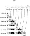
- FIG. 5 is a view for explaining tone conversion of the character CMYK data.
- FIG. 5 corresponds to the tone converting process in step S105.
- data c31 indicates data of the first 8 bits at a first line of the character CMYK data c3. Since the tone of the character CMYK data c3 is 8 bits, each dot (dot c311 through dot c318) of the data c31 is formed by 8 bits. The numerical value indicated in each dot shows the tone value of the dot.
- dot c311 is a subject of the first time tone conversion.
- the tone value of the dot c311 is "22" and therefore conversion to dot c311a of four tones (2 bits) is made based on the dither pattern d22 of level 22.
- dots are also converted to a dot of 2 bits based on the dither pattern corresponding to the tone value of the dot. Accordingly, dot c312, dot c313, dot c314, dot c315, dot c316, dot c317, and dot c318 are respectively converted to dot c312a, dot c313a, dot c314a, dot c315a, dot c316a, dot c317a, and dot c318a. At the third and fifth conversions, two dots are converted at one time. This is because conversion is done at one time by using the same dither pattern in a case where the dot having the same tone value continues.
- FIG. 6 is a view for explaining tone conversion of the image CMYK data.
- FIG. 6 corresponds to the tone converting process in step s107.
- data i21 indicate data of first 4 dots of the first line of the image CMYK data i2. Since the tone of the image CMYK data i2 is 8 bits, each dot of the data i21, namely dot i211 through dot i214, is formed by 8 bits.
- the numerical value indicated in each dot of FIG. 6 indicates the tone value of the dot.
- the dot i211 is a subject of the first time tone conversion. Since the tone value of the dot i211 is "22", conversion to the dot i211a and the dot i211b of four tones (2 bits) are made based on the dither pattern d22 of level 22. In other words, one dot is converted to 2 dots (4 bits).
- the dot i211a is a dot corresponding to the position of the dot 211 in the dither pattern d22.
- the dot 211b is a dot neighboring at a right side of the dot corresponding to the position of the dot 211 in the dither pattern d22.
- the converted dot is extracted from a dot corresponding to the original dot in the dot pattern.
- Other dots of the data i211 are also converted to 2 dots (4 bits) where one dot is four tones. Therefore, dot i212 is converted to dot i212a and dot i212b; dot i213 is converted to dot i213a and dot i213b; and dot i214 is converted to dot i214a and dot i214b.
- dot 212 and dot i213 are converted at one time at the second tone conversion is that tone values of these dots are the same.
- the image CMYK data i2 are converted to the image data of two time tone (4 bits) of the character CMYK data c3.
- the number of dots of data after the sixth conversion in FIG. 5 is done and data after the third conversion in FIG. 6 is done are consistent with each other. Since each of the number of bits per dot is 2 bits, the numbers of both bits, namely pixel densities are consistent with each other. In other words, the pixel densities of data after tone conversion of 8 dots of the character CMYK data c3 and data after tone conversion of 4 dots of the image CMYK data i2 are consistent with each other.
- the pixel densities of data (character CMYK data c4) after tone conversion of the character CMYK data c3 of 600 dpi in the main scanning direction and data (image CMYK data i3) after tone conversion of the image CMYK data i2 of 300 dpi are consistent with each other.
- the image CMYK data i3 and the character CMYK data c4 are synthesized after the tone modulation is performed, the image CMYK data i3 are treated as the image data having resolution of 600 ⁇ 300 dpi and tone of 2 bits. Therefore, it is necessary to do tone conversion of the image CMYK data i3 by a dither pattern expected to be treated as such image data.
- the image processing apparatus 10 image processing part 12 of this embodiment, for the character data (character object) in the document data, the image data are generated with high precision. Therefore, regarding characters, it is possible to obtain good printing results with high quality.
- the timing when the gradation conversion is made is after the color space is changed and before the image data of each object are synthesized (namely a latter half of the image processing step). Therefore, it is possible to prevent increase of processing workload.
- the embodiment of the present invention can provide an image processing apparatus, image processing method and image processing program product whereby image quality can be improved while degradation of capability of the apparatus is prevented.
Landscapes
- Engineering & Computer Science (AREA)
- Multimedia (AREA)
- Signal Processing (AREA)
- Theoretical Computer Science (AREA)
- General Physics & Mathematics (AREA)
- General Engineering & Computer Science (AREA)
- Physics & Mathematics (AREA)
- Human Computer Interaction (AREA)
- Image Processing (AREA)
- Facsimile Image Signal Circuits (AREA)
- Editing Of Facsimile Originals (AREA)
- Dot-Matrix Printers And Others (AREA)
- Color, Gradation (AREA)
Claims (8)
- Bildverarbeitungsvorrichtung (10), konfiguriert, ein Druckbild zum Drucken von Dokumentdaten durch einen Drucker zu erzeugen, umfassend:ein erstes Verarbeitungsteil (13), konfiguriert, von in den Dokumentdaten enthaltenen Zeichendaten erste Verarbeitungsdaten mit einer n-fach höheren Auflösung in einer Hauptscanrichtung als eine von einem Druckbefehl eines Benutzers eingestellte Auflösung zu erzeugen und die ersten Verarbeitungsdaten durch ein Halbtonanzeigeverfahren in die im Drucker verfügbaren Farben tonumzuwandeln;ein zweites Verarbeitungsteil (14), konfiguriert, von in den Dokumentdaten enthaltenen Bilddaten tonumgewandelte zweite Verarbeitungsdaten mit einer Pixeldichte zu erzeugen, die eine Bit-Nummer pro Zoll ist, in Übereinstimmung mit einer Pixeldichte der ersten Verarbeitungsdaten, durch Ausführen einer n-fachen Tonumwandlung der in den Dokumentdaten enthaltenen Bilddaten, wobei die n-fache Tonumwandlung durch das Halbtonanzeigeverfahren einen Punkt der Bilddaten in n Punkte der tonumgewandelten zweiten Verarbeitungsdaten umwandelt; undein Druckbilderzeugungsteil (15), konfiguriert, das Druckbild durch das Synthetisieren der tonumgewandelten ersten Verarbeitungsdaten und der tonumgewandelten zweiten Verarbeitungsdaten zu erzeugen.
- Bildverarbeitungsvorrichtung nach Anspruch 1,
wobei das zweite Verarbeitungsteil die Tonumwandlung der Bilddaten so ausführt, dass der Ton der Vergrößerung der Auflösung durch das erste Verarbeitungsteil entspricht. - Bildverarbeitungsvorrichtung nach Anspruch 1 oder Anspruch 2,
wobei das erste Verarbeitungsteil die ersten Verarbeitungsdaten mit der Auflösung, die sich im Vergleich zur Auflösung des Druckbefehls in eine Hauptscanrichtung erstreckt, für die Zeichendaten erzeugt. - Bildverarbeitungsverfahren, ausgeführt durch eine Bildverarbeitungsvorrichtung (10), konfiguriert, ein Druckbild zum Drucken von Dokumentdaten durch einen Drucker (20) zu erzeugen, umfassend:einen ersten Schritt des Erzeugens anhand von in den Dokumentendaten enthaltenen Zeichendaten von ersten Verarbeitungsdaten mit einer n-fach höheren Auflösung als eine durch einen Druckbefehl eines Benutzers eingestellte Auflösung und der Tonumwandlung der ersten Verarbeitungsdaten in die im Drucker verfügbaren Töne durch ein Halbtonanzeigeverfahren;einen zweiten Schritt des Erzeugens anhand von in den Dokumentendaten enthaltenen Bilddaten von tonumgewandelten zweiten Verarbeitungsdaten mit einer Pixeldichte, die eine Bit-Nummer pro Zoll ist, in Übereinstimmung mit einer Pixeldichte der ersten Verarbeitungsdaten, durch Ausführen einer n-fachen Tonumwandlung der in den Dokumentdaten enthaltenen Bilddaten, wobei die n-fache Tonumwandlung durch das Halbtonanzeigeverfahren einen Punkt der Bilddaten in n Punkte der tonumgewandelten zweiten Verarbeitungsdaten umwandelt; undeinen Druckbild-Erzeugungsschritt des Erzeugens des Druckbilds durch Synthetisieren der tonumgewandelten ersten Verarbeitungsdaten und der tonumgewandelten zweiten Verarbeitungsdaten.
- Bildverarbeitungsverfahren nach Anspruch 4,
wobei der zweite Verarbeitungsschritt die Tonumwandlung der Bilddaten ausführt, damit der Ton der Vergrößerung der Auflösung durch den ersten Verarbeitungsschritt entspricht. - Bildverarbeitungsverfahren nach Anspruch 4 oder Anspruch 5,
wobei der erste Verarbeitungsschritt die ersten Verarbeitungsdaten mit der Auflösung, die sich im Vergleich zur Auflösung des Druckbefehls in eine Hauptscanrichtung erstreckt, für die Zeichendaten erzeugt. - Computerprogramm, umfassend ein Programmcodemittel, das, wenn es auf einem Computersystem ausgeführt wird, ein Computersystem anweist, die Schritte nach einem der Ansprüche 4 bis 6 auszuführen.
- Computerlesbares Speichermedium mit einem darauf aufgezeichneten Programmcodemittel, dass, wenn es auf einem Computersystem ausgeführt wird, ein Computersystem anweist, die Schritte nach einem der Ansprüche 4 bis 6 auszuführen.
Applications Claiming Priority (3)
| Application Number | Priority Date | Filing Date | Title |
|---|---|---|---|
| JP2006178295 | 2006-06-28 | ||
| JP2007147353A JP4564986B2 (ja) | 2006-06-28 | 2007-06-01 | 画像処理装置、画像処理方法及び画像処理プログラム |
| PCT/JP2007/062060 WO2008001622A1 (en) | 2006-06-28 | 2007-06-07 | Image processing apparatus, image processing method and image processing program product |
Publications (3)
| Publication Number | Publication Date |
|---|---|
| EP2033432A1 EP2033432A1 (de) | 2009-03-11 |
| EP2033432A4 EP2033432A4 (de) | 2010-04-07 |
| EP2033432B1 true EP2033432B1 (de) | 2017-08-09 |
Family
ID=38845390
Family Applications (1)
| Application Number | Title | Priority Date | Filing Date |
|---|---|---|---|
| EP07767122.0A Not-in-force EP2033432B1 (de) | 2006-06-28 | 2007-06-07 | Bildverarbeitungsvorrichtung, bildverarbeitungsverfahren und bildverarbeitungsprogrammprodukt |
Country Status (6)
| Country | Link |
|---|---|
| US (1) | US8427694B2 (de) |
| EP (1) | EP2033432B1 (de) |
| JP (1) | JP4564986B2 (de) |
| KR (1) | KR20080032638A (de) |
| CN (1) | CN101346981B (de) |
| WO (1) | WO2008001622A1 (de) |
Families Citing this family (6)
| Publication number | Priority date | Publication date | Assignee | Title |
|---|---|---|---|---|
| WO2010090130A1 (en) * | 2009-02-06 | 2010-08-12 | Semiconductor Energy Laboratory Co., Ltd. | Method for driving display device |
| JP5483966B2 (ja) * | 2009-09-17 | 2014-05-07 | キヤノン株式会社 | 印刷装置及び印刷制御装置とその制御方法 |
| JP5675160B2 (ja) * | 2010-04-28 | 2015-02-25 | キヤノン株式会社 | 印刷装置、画像処理方法及びプログラム |
| WO2013150915A1 (ja) * | 2012-04-04 | 2013-10-10 | キヤノン株式会社 | 画像処理装置、画像処理方法およびプログラム |
| JP6056524B2 (ja) * | 2013-02-08 | 2017-01-11 | セイコーエプソン株式会社 | プリンターおよびプリンターの印刷制御方法 |
| CN111045617B (zh) * | 2019-12-27 | 2023-12-08 | 湖南鼎一致远科技发展有限公司 | 一种图片灰阶的打印方法、系统、控制芯片及打印机 |
Family Cites Families (20)
| Publication number | Priority date | Publication date | Assignee | Title |
|---|---|---|---|---|
| GB1582954A (en) | 1976-06-28 | 1981-01-21 | Crosfield Electronics Ltd | Printing methods and apparatus |
| US5579446A (en) | 1994-01-27 | 1996-11-26 | Hewlett-Packard Company | Manual/automatic user option for color printing of different types of objects |
| US5704021A (en) | 1994-01-27 | 1997-12-30 | Hewlett-Packard Company | Adaptive color rendering by an inkjet printer based on object type |
| JPH07256936A (ja) | 1994-03-17 | 1995-10-09 | Canon Inc | 画像形成装置 |
| JPH09289588A (ja) * | 1996-04-24 | 1997-11-04 | Tec Corp | 画像処理装置 |
| JP3658093B2 (ja) * | 1996-07-23 | 2005-06-08 | キヤノン株式会社 | 画像形成装置及びその制御方法 |
| JP3116994B2 (ja) * | 1996-08-29 | 2000-12-11 | 富士ゼロックス株式会社 | 画質予測装置および方法ならびに画質制御装置および方法 |
| JPH1093816A (ja) * | 1996-09-13 | 1998-04-10 | Ricoh Co Ltd | デジタル画像処理装置 |
| JPH10329363A (ja) | 1997-05-29 | 1998-12-15 | Seiko Epson Corp | 画像形成装置、方法及びプリンタ |
| JPH11191873A (ja) * | 1997-12-25 | 1999-07-13 | Fuji Photo Film Co Ltd | 電子カメラ |
| US6735341B1 (en) | 1998-06-18 | 2004-05-11 | Minolta Co., Ltd. | Image processing device and method and recording medium for recording image processing program for same |
| JP2000013611A (ja) | 1998-06-18 | 2000-01-14 | Minolta Co Ltd | 画像処理装置および方法ならびに画像処理プログラムを記録した記録媒体 |
| JP2002271622A (ja) | 2001-03-09 | 2002-09-20 | Canon Inc | 印刷装置及びその制御方法 |
| JP3762319B2 (ja) * | 2002-03-15 | 2006-04-05 | キヤノン株式会社 | 画像処理方法、画像処理装置及び画像処理システム |
| JP2004180099A (ja) | 2002-11-28 | 2004-06-24 | Matsushita Electric Ind Co Ltd | 画像処理装置 |
| JP4386339B2 (ja) * | 2003-10-10 | 2009-12-16 | 株式会社リコー | 画像形成装置および画像形成方法 |
| CN100493915C (zh) * | 2004-05-20 | 2009-06-03 | 光宝科技股份有限公司 | 具有双分辨率的打印方法 |
| JP2006074305A (ja) | 2004-09-01 | 2006-03-16 | Ricoh Co Ltd | 階調再現方法、画像形成装置及びプリンタドライバ |
| JP2006103045A (ja) * | 2004-10-01 | 2006-04-20 | Seiko Epson Corp | 画像形成装置 |
| JP4697933B2 (ja) * | 2004-11-15 | 2011-06-08 | キヤノン株式会社 | 画像処理装置および画像入出力装置およびそれらの方法 |
-
2007
- 2007-06-01 JP JP2007147353A patent/JP4564986B2/ja not_active Expired - Fee Related
- 2007-06-07 WO PCT/JP2007/062060 patent/WO2008001622A1/en not_active Ceased
- 2007-06-07 US US12/063,862 patent/US8427694B2/en not_active Expired - Fee Related
- 2007-06-07 CN CN2007800008800A patent/CN101346981B/zh not_active Expired - Fee Related
- 2007-06-07 KR KR1020087004744A patent/KR20080032638A/ko not_active Ceased
- 2007-06-07 EP EP07767122.0A patent/EP2033432B1/de not_active Not-in-force
Also Published As
| Publication number | Publication date |
|---|---|
| EP2033432A4 (de) | 2010-04-07 |
| US20080218785A1 (en) | 2008-09-11 |
| KR20080032638A (ko) | 2008-04-15 |
| EP2033432A1 (de) | 2009-03-11 |
| CN101346981B (zh) | 2011-03-16 |
| US8427694B2 (en) | 2013-04-23 |
| CN101346981A (zh) | 2009-01-14 |
| JP4564986B2 (ja) | 2010-10-20 |
| JP2008035489A (ja) | 2008-02-14 |
| WO2008001622A1 (en) | 2008-01-03 |
Similar Documents
| Publication | Publication Date | Title |
|---|---|---|
| KR100660453B1 (ko) | 화상 처리 장치, 묘화 데이터 처리 방법 및 이 방법을실행하기 위한 프로그램 | |
| EP2033432B1 (de) | Bildverarbeitungsvorrichtung, bildverarbeitungsverfahren und bildverarbeitungsprogrammprodukt | |
| US8564833B2 (en) | Control apparatus, controlling method, program and recording medium | |
| JP4925899B2 (ja) | ビットマップベースのトラッピング方法及び印刷システム | |
| JP2008179120A (ja) | 画像形成システム、及び、画像形成プログラム | |
| US7315402B2 (en) | Image forming apparatus and method for selecting an optimal image space frequency for an output image | |
| US5701363A (en) | Binary to multi-value conversion apparatus for improved image reduction and enlargement | |
| JP4514168B2 (ja) | 画像処理システム及び画像処理方法 | |
| JP4093264B2 (ja) | プリント媒体に埋め込まれたデータを検索するための方法及びプリント媒体に埋め込まれたデータを検索する方法を機器に実行させるための命令プログラムを含んだ機器判読可能な媒体 | |
| US7760390B2 (en) | Binary resolution conversion aparatus and method | |
| JP2000332995A (ja) | 画像データ生成方法および記録媒体 | |
| JP3087845B2 (ja) | 原稿画像をスキャナで読み取って拡大印刷するデジタル画像処理方法 | |
| JP4753253B2 (ja) | 画像処理装置 | |
| JP4217332B2 (ja) | 画像処理装置及びその方法、コンピュータ可読メモリ | |
| JP4306841B2 (ja) | 画像処理装置及びその方法、コンピュータ可読メモリ | |
| JPH11196246A (ja) | 画像形成装置 | |
| JP4337670B2 (ja) | 画像処理装置、画像処理方法、及びプログラム | |
| US20120121201A1 (en) | Image processing apparatus and image processing method | |
| JP2007072468A (ja) | カラー画像形成装置と画像形成方法 | |
| JP3185435B2 (ja) | 画像形成装置 | |
| JP2010061363A (ja) | 画像処理装置及びプログラム | |
| JPH068533A (ja) | 画像形成装置 | |
| JP2006191294A (ja) | 画像処理装置、プログラムおよび画像処理方法 | |
| JP2003036445A (ja) | 画像処理装置 | |
| JP2006135395A (ja) | 画像形成装置 |
Legal Events
| Date | Code | Title | Description |
|---|---|---|---|
| PUAI | Public reference made under article 153(3) epc to a published international application that has entered the european phase |
Free format text: ORIGINAL CODE: 0009012 |
|
| 17P | Request for examination filed |
Effective date: 20080208 |
|
| AK | Designated contracting states |
Kind code of ref document: A1 Designated state(s): AT BE BG CH CY CZ DE DK EE ES FI FR GB GR HU IE IS IT LI LT LU LV MC MT NL PL PT RO SE SI SK TR |
|
| AX | Request for extension of the european patent |
Extension state: AL BA HR MK RS |
|
| DAX | Request for extension of the european patent (deleted) | ||
| RBV | Designated contracting states (corrected) |
Designated state(s): DE FR GB IT NL |
|
| A4 | Supplementary search report drawn up and despatched |
Effective date: 20100305 |
|
| GRAP | Despatch of communication of intention to grant a patent |
Free format text: ORIGINAL CODE: EPIDOSNIGR1 |
|
| STAA | Information on the status of an ep patent application or granted ep patent |
Free format text: STATUS: GRANT OF PATENT IS INTENDED |
|
| INTG | Intention to grant announced |
Effective date: 20170103 |
|
| RIN1 | Information on inventor provided before grant (corrected) |
Inventor name: SUGIMOTO, KAZUKI |
|
| GRAS | Grant fee paid |
Free format text: ORIGINAL CODE: EPIDOSNIGR3 |
|
| GRAA | (expected) grant |
Free format text: ORIGINAL CODE: 0009210 |
|
| STAA | Information on the status of an ep patent application or granted ep patent |
Free format text: STATUS: THE PATENT HAS BEEN GRANTED |
|
| AK | Designated contracting states |
Kind code of ref document: B1 Designated state(s): DE FR GB IT NL |
|
| REG | Reference to a national code |
Ref country code: GB Ref legal event code: FG4D |
|
| REG | Reference to a national code |
Ref country code: DE Ref legal event code: R096 Ref document number: 602007051940 Country of ref document: DE |
|
| REG | Reference to a national code |
Ref country code: NL Ref legal event code: MP Effective date: 20170809 |
|
| PG25 | Lapsed in a contracting state [announced via postgrant information from national office to epo] |
Ref country code: NL Free format text: LAPSE BECAUSE OF FAILURE TO SUBMIT A TRANSLATION OF THE DESCRIPTION OR TO PAY THE FEE WITHIN THE PRESCRIBED TIME-LIMIT Effective date: 20170809 |
|
| REG | Reference to a national code |
Ref country code: DE Ref legal event code: R097 Ref document number: 602007051940 Country of ref document: DE |
|
| PG25 | Lapsed in a contracting state [announced via postgrant information from national office to epo] |
Ref country code: IT Free format text: LAPSE BECAUSE OF FAILURE TO SUBMIT A TRANSLATION OF THE DESCRIPTION OR TO PAY THE FEE WITHIN THE PRESCRIBED TIME-LIMIT Effective date: 20170809 |
|
| PLBE | No opposition filed within time limit |
Free format text: ORIGINAL CODE: 0009261 |
|
| STAA | Information on the status of an ep patent application or granted ep patent |
Free format text: STATUS: NO OPPOSITION FILED WITHIN TIME LIMIT |
|
| REG | Reference to a national code |
Ref country code: FR Ref legal event code: PLFP Year of fee payment: 12 |
|
| 26N | No opposition filed |
Effective date: 20180511 |
|
| PGFP | Annual fee paid to national office [announced via postgrant information from national office to epo] |
Ref country code: DE Payment date: 20180625 Year of fee payment: 12 |
|
| PGFP | Annual fee paid to national office [announced via postgrant information from national office to epo] |
Ref country code: FR Payment date: 20180620 Year of fee payment: 12 |
|
| PGFP | Annual fee paid to national office [announced via postgrant information from national office to epo] |
Ref country code: GB Payment date: 20180620 Year of fee payment: 12 |
|
| REG | Reference to a national code |
Ref country code: DE Ref legal event code: R119 Ref document number: 602007051940 Country of ref document: DE |
|
| GBPC | Gb: european patent ceased through non-payment of renewal fee |
Effective date: 20190607 |
|
| PG25 | Lapsed in a contracting state [announced via postgrant information from national office to epo] |
Ref country code: GB Free format text: LAPSE BECAUSE OF NON-PAYMENT OF DUE FEES Effective date: 20190607 Ref country code: DE Free format text: LAPSE BECAUSE OF NON-PAYMENT OF DUE FEES Effective date: 20200101 |
|
| PG25 | Lapsed in a contracting state [announced via postgrant information from national office to epo] |
Ref country code: FR Free format text: LAPSE BECAUSE OF NON-PAYMENT OF DUE FEES Effective date: 20190630 |