EP2033505A1 - Fliesmaschinentransport und Speichervorrichtungen und Verfahren - Google Patents
Fliesmaschinentransport und Speichervorrichtungen und Verfahren Download PDFInfo
- Publication number
- EP2033505A1 EP2033505A1 EP08015650A EP08015650A EP2033505A1 EP 2033505 A1 EP2033505 A1 EP 2033505A1 EP 08015650 A EP08015650 A EP 08015650A EP 08015650 A EP08015650 A EP 08015650A EP 2033505 A1 EP2033505 A1 EP 2033505A1
- Authority
- EP
- European Patent Office
- Prior art keywords
- wheel apparatus
- tilling machine
- mounting frame
- drag bar
- tilling
- Prior art date
- Legal status (The legal status is an assumption and is not a legal conclusion. Google has not performed a legal analysis and makes no representation as to the accuracy of the status listed.)
- Granted
Links
- 238000000034 method Methods 0.000 title claims abstract description 11
- 238000005096 rolling process Methods 0.000 claims description 2
- 230000000063 preceeding effect Effects 0.000 claims 3
- 239000002689 soil Substances 0.000 description 4
- 238000010168 coupling process Methods 0.000 description 3
- 238000010413 gardening Methods 0.000 description 3
- 230000008878 coupling Effects 0.000 description 2
- 238000005859 coupling reaction Methods 0.000 description 2
- 238000013461 design Methods 0.000 description 2
- 230000000087 stabilizing effect Effects 0.000 description 2
- 230000000712 assembly Effects 0.000 description 1
- 238000000429 assembly Methods 0.000 description 1
- 230000001010 compromised effect Effects 0.000 description 1
- 230000007423 decrease Effects 0.000 description 1
- 238000010348 incorporation Methods 0.000 description 1
- 238000003780 insertion Methods 0.000 description 1
- 230000037431 insertion Effects 0.000 description 1
- 230000001788 irregular Effects 0.000 description 1
- 238000012986 modification Methods 0.000 description 1
- 230000004048 modification Effects 0.000 description 1
- 230000000979 retarding effect Effects 0.000 description 1
- 238000012546 transfer Methods 0.000 description 1
Images



Classifications
-
- A—HUMAN NECESSITIES
- A01—AGRICULTURE; FORESTRY; ANIMAL HUSBANDRY; HUNTING; TRAPPING; FISHING
- A01B—SOIL WORKING IN AGRICULTURE OR FORESTRY; PARTS, DETAILS, OR ACCESSORIES OF AGRICULTURAL MACHINES OR IMPLEMENTS, IN GENERAL
- A01B33/00—Tilling implements with rotary driven tools, e.g. in combination with fertiliser distributors or seeders, with grubbing chains, with sloping axles, with driven discs
- A01B33/02—Tilling implements with rotary driven tools, e.g. in combination with fertiliser distributors or seeders, with grubbing chains, with sloping axles, with driven discs with tools on horizontal shaft transverse to direction of travel
- A01B33/028—Tilling implements with rotary driven tools, e.g. in combination with fertiliser distributors or seeders, with grubbing chains, with sloping axles, with driven discs with tools on horizontal shaft transverse to direction of travel of the walk-behind type
-
- A—HUMAN NECESSITIES
- A01—AGRICULTURE; FORESTRY; ANIMAL HUSBANDRY; HUNTING; TRAPPING; FISHING
- A01B—SOIL WORKING IN AGRICULTURE OR FORESTRY; PARTS, DETAILS, OR ACCESSORIES OF AGRICULTURAL MACHINES OR IMPLEMENTS, IN GENERAL
- A01B33/00—Tilling implements with rotary driven tools, e.g. in combination with fertiliser distributors or seeders, with grubbing chains, with sloping axles, with driven discs
- A01B33/16—Tilling implements with rotary driven tools, e.g. in combination with fertiliser distributors or seeders, with grubbing chains, with sloping axles, with driven discs with special additional arrangements
Definitions
- the subject matter disclosed herein relates generally to apparatuses and methods designed to facilitate the transport and storage of tilling machines, and more particularly to providing a multi-positionable, auxiliary wheel apparatus for a tilling machine, such as a mini-tiller.
- a wheel apparatus would be advantageous to facilitate the transport of tilling machines, particularly mini-tillers. Further, a wheel apparatus that is readily removable would not take away from the maneuverability and compact design of the mini-tiller when in use as a tilling machine.
- Wheel assemblies are currently available on tilling machines, particularly self-propelled tillers and tillers designed for larger applications.
- Some tilling machines have wheels that are vertically adjustable to allow for a working mode in which tiller tine depth can be selectively controlled at a plurality of depths, as well as a transport mode wherein the tiller tines are maintained above the soil and the weight of the tilling machine is supported on the wheels such that the tilling machine can be rolled during transport.
- Other tilling machines utilize the wheels as a means of propulsion by directing power from the engine to the ground engaging wheels.
- Still yet, other tilling machines utilize wheels as a stabilizing means while in working mode.
- wheel apparatuses and methods are provided for the transport and storage of tilling machines such as mini-tillers.
- a tilling machine such as a mini-tiller
- tiller T is illustrated as a mini-tiller. It can be appreciated, however, that the present disclosure is not limited to mini-tillers and that the present disclosure can apply to and be used with any suitable tilling apparatus.
- tiller T can till soil by rotating tiller tines generally designated TT.
- Tiller T can be powered by a motor M that can be, for example, a gasoline powered motor. Motor M can transfer power to tiller tines TT such that tiller tines TT can be rotated to till soil.
- Tiller T can include a handle generally designated H that can permit a user to guide and steer tiller T.
- a drag bar DB can be attached to or part of tiller T and can be used for contacting the soil during tilling to provide stability and create resistance during operation, thereby retarding the forward motion of tiller T .
- a wheel apparatus generally designated WA can attach to drag bar DB to facilitate transportation of tiller T when in a transport position ( Figure 1a ) and to facilitate storage of tiller T when in a storage position ( Figure 1 b) .
- Wheel apparatus WA can be fixedly attached to tiller T in any suitable manner as known to those of skill in the art.
- wheel apparatus WA can comprise a mounting frame generally designated MF that can be removably attached to drag bar DB .
- wheel apparatus WA can be linked or attached to tiller T with coupling methods known to those of skill in the art.
- drag bar DB can be substantially L-shaped and can have a substantially vertical portion 10 and a substantially horizontal portion 12 .
- Vertical portion 10 of drag bar DB can define a plurality of holes generally designated DBH for varying the attachment height of drag bar DB to the rear portion of tiller T for facilitating a transport position and a storage position, wherein horizontal portion 12 of drag bar DB can extend rearwardly therefrom.
- a drag bar pin DBP can be received within holes DBH for securing drag bar DB to tiller T .
- a key K can be attached to drag bar pin DBP to prevent removal of drag bar pin DBP when inserted into holes DBH.
- Horizontal portion 12 of drag bar DB can define an aperture generally designated 14 that can receive a locking pin P1 for lockably attaching drag bar DB to mounting frame MF .
- mounting frame MF of wheel apparatus WA can have a sleeve portion SP that can define an interior space generally designated IS .
- Horizontal portion 12 of drag bar DB can be configured to be slidably received within interior space IS .
- Sleeve portion SP can define a hole generally designated H1 that can align with aperture 14 of drag bar DB .
- Locking pin P1 can be inserted into hole H1 of sleeve portion SP and can then be guided through aperture 14 of drag bar DB .
- Locking pin P1 can exit sleeve portion SP through a corresponding hole H1 on the side of sleeve portion SP opposite the insertion side.
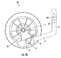
- Mounting frame MF can further include an axle housing AH .
- Axle housing AH can be substantially elongate and hollow for receiving an axle A .
- Axle A can be rotatably mounted within axle housing AH and can extend horizontally from both ends of axle housing AH to provide for the attachment of a plurality of wheels W to each end of axle A .
- axle A and wheels W can rotate freely.
- a plurality of endcaps 20 can be attached to wheels W to prevent axle A from extending beyond wheels W .
- wheel apparatus WA can comprise one wheel W that can be attached to mounting frame MF such that a user could transport tiller T by rolling tiller T on wheel W and the user can also stabilize tiller T in a storage position in a stabilizing manner similar to that of a tripod.
- wheel apparatus WA can be attached to drag bar DB in one or more positions for providing various functions.
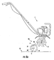
- a transport position is illustrated in Figures 3a , 4a , 5a , 6a , 6b and 8a .
- the transport position can be used when the user is not operating tiller T in a tilling manner.
- wheel apparatus WA can be used to lift and maintain tiller tines TT off the ground surface.
- the user can transport tiller T to a storage location or other area to be tilled without awkwardly attempting to carry tiller T or to roll tiller tines TT over a damaging surface.
- the user can attach wheel apparatus WA to tiller T by sliding drag bar DB within sleeve portion SP and coupling thereto with locking pin P1.
- sleeve portion SP of mounting frame MF and horizontal portion 12 ( Figures 5a , 6a , 6b and 8a ) of drag bar DB can be fixedly oriented substantially above axle A .
- wheel apparatus WA By attaching wheel apparatus WA to drag bar DB in the transport position, tiller T and tiller tines TT can be maintained in a spaced-apart manner above a ground surface generally designated GS , as illustrated in Figure 8a .
- the weight of the tiller T can be supported by wheels W of wheel apparatus WA , wherein tiller T can be rolled during transport.
- wheel apparatus WA can be attached to drag bar DB of tiller T in a storage position.
- the storage position can be used when tiller T is stored in a standing position.
- wheel apparatus WA can be used to provide additional stability to tiller T , thereby aiding in preventing tiller T from easily being tipped over due to the irregular shape of tiller tines TT .
- wheel apparatus WA is configured to permit tiller tines TT to rest on the ground surface.
- wheels W and tiller tines TT can more evenly distribute the weight of tiller T to provide a more stable storage position.
- the user can attach wheel apparatus WA to tiller T by sliding drag bar DB within sleeve portion SP and coupling thereto with locking pin P1.
- sleeve portion SP of mounting frame MF and horizontal portion 12 ( Figures 7a , 7b and 8b ) of drag bar DB can be fixedly oriented substantially below axle A .
- the tines TT of tiller T and wheels W of the wheel apparatus WA can be simultaneously in contact with ground surface GS , as shown in Figure 8b , to stabilize tiller T , which is particularly useful for storage of tiller T .
- the user can easily switch wheel apparatus WA from a transport position to a storage position by removing locking pin P1 and switching the position of wheels W .
- Wheel apparatus WA can be easily changed between the transport and storage positions, and visa-versa, by removing locking pin P1, sliding wheel apparatus WA off of drag bar DB , flipping the wheel apparatus WA over, and re-attaching wheel apparatus WA to drag bar DB .
- Wheel apparatus WA can be configured such that no vertical adjustment of vertical portion 10 of drag bar DB is necessary when switching from storage position to transport position or vice-versa. In such a configuration, drag bar pin DBP can remain in the same hole DBH in both positions.
- Drag bar DB can be adjusted vertically using various holes DBH and drag bar pin DBP to adjust wheel apparatus WA to accommodate various sized tillers T .
- wheel apparatus WA can be an auxiliary device that can be completely removed and remain unattached when desired such as, for example, when tiller T is in operation.
- the embodiments disclosed herein provide apparatuses and methods to transport and store a mini-tiller or other suitable tilling machines by attaching, in a transport or storage position, an auxiliary wheel kit apparatus to the drag bar of the mini-tiller.
- a wheel apparatus can attach to a tilling machine, such as by attachment to a drag bar, in a transport position or a storage position.
- the wheel apparatus In the transport position, the wheel apparatus can maintain tiller tines of the tilling machine above the ground surface with the weight of the tilling machine supported on the wheel apparatus, thereby allowing the tilling machine to be rolled for transport.
- the wheel apparatus In the storage position, the wheel apparatus can be attached to the drag bar, whereby both the tiller tines and the wheel apparatus rest on the ground surface to provide stability to the tilling machine. During operation the wheel apparatus can be removed from the tilling machine.
Landscapes
- Life Sciences & Earth Sciences (AREA)
- Engineering & Computer Science (AREA)
- Mechanical Engineering (AREA)
- Soil Sciences (AREA)
- Environmental Sciences (AREA)
- Soil Working Implements (AREA)
- Agricultural Machines (AREA)
- Prostheses (AREA)
- Peptides Or Proteins (AREA)
- Micro-Organisms Or Cultivation Processes Thereof (AREA)
Applications Claiming Priority (1)
| Application Number | Priority Date | Filing Date | Title |
|---|---|---|---|
| US11/850,993 US7866409B2 (en) | 2007-09-06 | 2007-09-06 | Tilling machine transport and storage apparatuses and methods |
Publications (2)
| Publication Number | Publication Date |
|---|---|
| EP2033505A1 true EP2033505A1 (de) | 2009-03-11 |
| EP2033505B1 EP2033505B1 (de) | 2010-03-10 |
Family
ID=40070559
Family Applications (1)
| Application Number | Title | Priority Date | Filing Date |
|---|---|---|---|
| EP08015650A Ceased EP2033505B1 (de) | 2007-09-06 | 2008-09-04 | Fliesmaschinentransport und Speichervorrichtungen und Verfahren |
Country Status (4)
| Country | Link |
|---|---|
| US (1) | US7866409B2 (de) |
| EP (1) | EP2033505B1 (de) |
| AT (1) | ATE460075T1 (de) |
| DE (1) | DE602008000783D1 (de) |
Cited By (2)
| Publication number | Priority date | Publication date | Assignee | Title |
|---|---|---|---|---|
| EP2191706A1 (de) | 2008-11-26 | 2010-06-02 | Honda Motor Co., Ltd | Kleine Ackerfräse |
| CN107211603A (zh) * | 2017-05-17 | 2017-09-29 | 广西隆成机械设备制造有限公司 | 一种翻耕机 |
Families Citing this family (9)
| Publication number | Priority date | Publication date | Assignee | Title |
|---|---|---|---|---|
| DE102007000489B3 (de) * | 2007-09-12 | 2009-02-05 | Hilti Aktiengesellschaft | Handwerkzeugmaschine |
| US7963344B2 (en) | 2008-09-03 | 2011-06-21 | Black & Decker Inc. | Tiller with removable battery |
| US8627897B2 (en) | 2008-09-03 | 2014-01-14 | Black & Decker Inc. | Tiller housing |
| US8499848B2 (en) | 2011-08-05 | 2013-08-06 | Techtronic Outdoor Products Technology Limited | Gas tiller |
| US9763372B2 (en) | 2012-09-13 | 2017-09-19 | Husqvarna Ab | Detachable tiller tines |
| US9167737B2 (en) | 2013-05-22 | 2015-10-27 | Carts & Tools Technology, Inc. | Garden implement |
| CN103959941B (zh) * | 2014-03-18 | 2015-10-28 | 宁波奥晟机械有限公司 | 一种田园管理装置 |
| CN105165148A (zh) * | 2015-07-14 | 2015-12-23 | 河南科技大学 | 一种用于烟叶拔秆和烟田松土的旋转刀辊 |
| CN114097319B (zh) * | 2021-11-29 | 2023-05-16 | 金华市农业科学研究院(浙江省农业机械研究院) | 一种果园旋耕机 |
Citations (7)
| Publication number | Priority date | Publication date | Assignee | Title |
|---|---|---|---|---|
| US3952490A (en) * | 1974-11-15 | 1976-04-27 | Brockman Furn O | Lawn rake |
| US5054278A (en) | 1990-05-14 | 1991-10-08 | Thorndike Charles E | Operation of long-handled tools |
| FR2666718A1 (fr) * | 1990-09-13 | 1992-03-20 | Staub Tracteurs Motocult | Dispositif d'attelage multi-usages. |
| EP0774200A1 (de) | 1995-05-24 | 1997-05-21 | Yanmar Agricultural Equipment Co., Ltd. | Landwirtschaftliche arbeitsmaschine |
| EP1201110A1 (de) | 2000-10-24 | 2002-05-02 | Honda Giken Kogyo Kabushiki Kaisha | Haltebügel für Kultivator |
| EP1329611A2 (de) * | 2002-01-16 | 2003-07-23 | Honda Giken Kogyo Kabushiki Kaisha | Landwirtschaftliche Maschine mit einem rotierenden Gerät an der Vorderseite |
| US20030178208A1 (en) * | 2002-03-11 | 2003-09-25 | Abenroth Jon M. T. | Electric garden tiller |
Family Cites Families (31)
| Publication number | Priority date | Publication date | Assignee | Title |
|---|---|---|---|---|
| US913953A (en) * | 1908-02-20 | 1909-03-02 | Adolphus P Granger | Implement for hoeing and topping growing plants. |
| US1704986A (en) * | 1927-08-01 | 1929-03-12 | Marcy Frank Earl | Spiked lawn roller |
| US1878442A (en) * | 1929-06-20 | 1932-09-20 | Mrs H W Goode | Rotary garden cultivator |
| CH224903A (de) * | 1942-04-27 | 1942-12-31 | Rapid Motormaeher A G | Triebradlose, ihren Motor selbsttragende Bodenfräse. |
| US2834276A (en) * | 1955-07-20 | 1958-05-13 | Harold M Schwab | Power driven soil spades |
| US2903077A (en) * | 1957-06-10 | 1959-09-08 | Simplicity Mfg Company | Soil tilling device |
| US3074490A (en) * | 1961-04-26 | 1963-01-22 | Burns Sam | Rotary tiller |
| US3282353A (en) * | 1965-07-09 | 1966-11-01 | John S Troyer | Soil cutting implement for rotary tillers |
| US3620307A (en) * | 1969-10-13 | 1971-11-16 | Antone Vilela | Golf course green or yard border cutter |
| US3792734A (en) * | 1972-01-10 | 1974-02-19 | Atlas Tool Mfg Co | Self-propelled tiller |
| US3901325A (en) * | 1974-10-07 | 1975-08-26 | Harold W Richards | Cultivator having a floating plant guard |
| US4165786A (en) * | 1977-11-10 | 1979-08-28 | Deere & Company | Walk-behind tiller and handle mounting therefor |
| US4164983A (en) * | 1978-02-21 | 1979-08-21 | Deere & Company | Walk-behind filler with combined drag stake and wheel |
| US4191259A (en) * | 1978-06-19 | 1980-03-04 | Boren Charles F | Rotary cultivator and mulcher |
| US4224996A (en) * | 1978-12-07 | 1980-09-30 | Deere & Company | Control mechanism for a walk-behind rotary tiller |
| USRE32467E (en) * | 1979-05-10 | 1987-08-04 | Plow attachment for converting a rotary tiller into a plow | |
| US4336760A (en) * | 1981-03-13 | 1982-06-29 | Improved Lawn Equipment Corporation | Earth working apparatus including aerators and material dispensers |
| USD280824S (en) * | 1982-10-26 | 1985-10-01 | Honda Giken Kogyo Kabushiki Kaisha | Cultivator |
| US4699219A (en) * | 1984-04-02 | 1987-10-13 | Garden Way Incorporated | Cultivator drag bar and mounting therefor |
| US4621697A (en) * | 1985-03-11 | 1986-11-11 | Webb Roger C | Garden tiller attachment |
| US4811794A (en) * | 1986-11-24 | 1989-03-14 | Greene Benjamin F | Garden tiller with reciprocating tines |
| US5156217A (en) * | 1989-05-15 | 1992-10-20 | Kawasaki Jukogyo Kabushiki Kaisha | Edger with improved rear wheel adjustment |
| US5197551A (en) * | 1991-09-16 | 1993-03-30 | Farley John L | Extended drag tool for a front tine tiller |
| US6131670A (en) * | 1999-11-29 | 2000-10-17 | Johnson; John Travis | Rotary tiller attachment to facilitate towing |
| JP3839371B2 (ja) * | 2002-07-11 | 2006-11-01 | 本田技研工業株式会社 | 歩行型作業機 |
| DE10248642A1 (de) * | 2002-10-18 | 2004-04-29 | Andreas Stihl Ag & Co. Kg | Handgeführtes Arbeitsgerät |
| JP4139251B2 (ja) * | 2003-03-17 | 2008-08-27 | 本田技研工業株式会社 | 電動管理機 |
| US7143835B2 (en) * | 2003-03-17 | 2006-12-05 | Honda Motor Co., Ltd. | Walk-behind electric working machine |
| JP4116904B2 (ja) * | 2003-03-17 | 2008-07-09 | 本田技研工業株式会社 | 歩行型電動管理機 |
| USD523026S1 (en) * | 2004-09-22 | 2006-06-13 | Honda Motor Co., Ltd. | Tiller |
| US20070163789A1 (en) * | 2006-01-17 | 2007-07-19 | Eastway Fair Company Limited | Cultivator/tiller |
-
2007
- 2007-09-06 US US11/850,993 patent/US7866409B2/en active Active
-
2008
- 2008-09-04 AT AT08015650T patent/ATE460075T1/de not_active IP Right Cessation
- 2008-09-04 EP EP08015650A patent/EP2033505B1/de not_active Ceased
- 2008-09-04 DE DE602008000783T patent/DE602008000783D1/de active Active
Patent Citations (7)
| Publication number | Priority date | Publication date | Assignee | Title |
|---|---|---|---|---|
| US3952490A (en) * | 1974-11-15 | 1976-04-27 | Brockman Furn O | Lawn rake |
| US5054278A (en) | 1990-05-14 | 1991-10-08 | Thorndike Charles E | Operation of long-handled tools |
| FR2666718A1 (fr) * | 1990-09-13 | 1992-03-20 | Staub Tracteurs Motocult | Dispositif d'attelage multi-usages. |
| EP0774200A1 (de) | 1995-05-24 | 1997-05-21 | Yanmar Agricultural Equipment Co., Ltd. | Landwirtschaftliche arbeitsmaschine |
| EP1201110A1 (de) | 2000-10-24 | 2002-05-02 | Honda Giken Kogyo Kabushiki Kaisha | Haltebügel für Kultivator |
| EP1329611A2 (de) * | 2002-01-16 | 2003-07-23 | Honda Giken Kogyo Kabushiki Kaisha | Landwirtschaftliche Maschine mit einem rotierenden Gerät an der Vorderseite |
| US20030178208A1 (en) * | 2002-03-11 | 2003-09-25 | Abenroth Jon M. T. | Electric garden tiller |
Cited By (3)
| Publication number | Priority date | Publication date | Assignee | Title |
|---|---|---|---|---|
| EP2191706A1 (de) | 2008-11-26 | 2010-06-02 | Honda Motor Co., Ltd | Kleine Ackerfräse |
| US8066081B2 (en) | 2008-11-26 | 2011-11-29 | Honda Motor Co., Ltd. | Small-sized tiller |
| CN107211603A (zh) * | 2017-05-17 | 2017-09-29 | 广西隆成机械设备制造有限公司 | 一种翻耕机 |
Also Published As
| Publication number | Publication date |
|---|---|
| EP2033505B1 (de) | 2010-03-10 |
| US7866409B2 (en) | 2011-01-11 |
| DE602008000783D1 (de) | 2010-04-22 |
| ATE460075T1 (de) | 2010-03-15 |
| US20090065221A1 (en) | 2009-03-12 |
Similar Documents
| Publication | Publication Date | Title |
|---|---|---|
| US7866409B2 (en) | Tilling machine transport and storage apparatuses and methods | |
| US8424613B2 (en) | Aerator for zero turn lawn equipment | |
| US8746377B1 (en) | Electric utility cart | |
| US5960889A (en) | Cordless soil tiller | |
| US7862068B2 (en) | Pin constructed for connecting a jack to an implement draft tongue and for supporting a PTO drive shaft assembly | |
| JP5730531B2 (ja) | 歩行型管理機 | |
| US3977477A (en) | Combination garden implement apparatus | |
| JP2010104302A (ja) | 歩行型耕耘管理機 | |
| CN219893867U (zh) | 园林工具 | |
| EP2191706B1 (de) | Kleine Ackerfräse | |
| KR101108645B1 (ko) | 이랑 이동용 대차 | |
| KR101975582B1 (ko) | 이동성이 향상된 파종기 | |
| EP1959783B1 (de) | Tasche mit rädern | |
| US20160338256A1 (en) | Landscaping Tow Apparatus | |
| JP2010154867A (ja) | 耕耘装置 | |
| US6808185B1 (en) | Garden tool caddy and dolly combination | |
| US4286671A (en) | Kit for converting a rotary tiller into a plow | |
| EP2570014A1 (de) | Verbesserte landwirtschaftliche Vorrichtung | |
| CN211184983U (zh) | 一种农业设施用农业除草装置 | |
| JP3199048U (ja) | 農作業用キャリア | |
| US11895936B2 (en) | Vehicle for cultivation and transportation | |
| KR102917880B1 (ko) | 전동식 보행관리기 | |
| US2785619A (en) | Adjustable stabilizing disk mounting | |
| CN221630539U (zh) | 一种数字化激光射击起倒靶机 | |
| CN110809926A (zh) | 一种电动多功能便携式农用机具 |
Legal Events
| Date | Code | Title | Description |
|---|---|---|---|
| PUAI | Public reference made under article 153(3) epc to a published international application that has entered the european phase |
Free format text: ORIGINAL CODE: 0009012 |
|
| 17P | Request for examination filed |
Effective date: 20080904 |
|
| AK | Designated contracting states |
Kind code of ref document: A1 Designated state(s): AT BE BG CH CY CZ DE DK EE ES FI FR GB GR HR HU IE IS IT LI LT LU LV MC MT NL NO PL PT RO SE SI SK TR |
|
| AX | Request for extension of the european patent |
Extension state: AL BA MK RS |
|
| GRAP | Despatch of communication of intention to grant a patent |
Free format text: ORIGINAL CODE: EPIDOSNIGR1 |
|
| RIN1 | Information on inventor provided before grant (corrected) |
Inventor name: MCDANIEL, ANDREW, JOSEPH Inventor name: VAUGHN, CHRISTOPHER, WAYNE |
|
| AKX | Designation fees paid |
Designated state(s): AT BE BG CH CY CZ DE DK EE ES FI FR GB GR HR HU IE IS IT LI LT LU LV MC MT NL NO PL PT RO SE SI SK TR |
|
| GRAS | Grant fee paid |
Free format text: ORIGINAL CODE: EPIDOSNIGR3 |
|
| GRAA | (expected) grant |
Free format text: ORIGINAL CODE: 0009210 |
|
| AK | Designated contracting states |
Kind code of ref document: B1 Designated state(s): AT BE BG CH CY CZ DE DK EE ES FI FR GB GR HR HU IE IS IT LI LT LU LV MC MT NL NO PL PT RO SE SI SK TR |
|
| REG | Reference to a national code |
Ref country code: GB Ref legal event code: FG4D |
|
| REG | Reference to a national code |
Ref country code: CH Ref legal event code: EP |
|
| REG | Reference to a national code |
Ref country code: IE Ref legal event code: FG4D |
|
| REF | Corresponds to: |
Ref document number: 602008000783 Country of ref document: DE Date of ref document: 20100422 Kind code of ref document: P |
|
| REG | Reference to a national code |
Ref country code: NL Ref legal event code: VDEP Effective date: 20100310 |
|
| PG25 | Lapsed in a contracting state [announced via postgrant information from national office to epo] |
Ref country code: HR Free format text: LAPSE BECAUSE OF FAILURE TO SUBMIT A TRANSLATION OF THE DESCRIPTION OR TO PAY THE FEE WITHIN THE PRESCRIBED TIME-LIMIT Effective date: 20100310 Ref country code: LT Free format text: LAPSE BECAUSE OF FAILURE TO SUBMIT A TRANSLATION OF THE DESCRIPTION OR TO PAY THE FEE WITHIN THE PRESCRIBED TIME-LIMIT Effective date: 20100310 Ref country code: NO Free format text: LAPSE BECAUSE OF FAILURE TO SUBMIT A TRANSLATION OF THE DESCRIPTION OR TO PAY THE FEE WITHIN THE PRESCRIBED TIME-LIMIT Effective date: 20100610 |
|
| LTIE | Lt: invalidation of european patent or patent extension |
Effective date: 20100310 |
|
| PG25 | Lapsed in a contracting state [announced via postgrant information from national office to epo] |
Ref country code: SI Free format text: LAPSE BECAUSE OF FAILURE TO SUBMIT A TRANSLATION OF THE DESCRIPTION OR TO PAY THE FEE WITHIN THE PRESCRIBED TIME-LIMIT Effective date: 20100310 Ref country code: PL Free format text: LAPSE BECAUSE OF FAILURE TO SUBMIT A TRANSLATION OF THE DESCRIPTION OR TO PAY THE FEE WITHIN THE PRESCRIBED TIME-LIMIT Effective date: 20100310 Ref country code: LV Free format text: LAPSE BECAUSE OF FAILURE TO SUBMIT A TRANSLATION OF THE DESCRIPTION OR TO PAY THE FEE WITHIN THE PRESCRIBED TIME-LIMIT Effective date: 20100310 Ref country code: FI Free format text: LAPSE BECAUSE OF FAILURE TO SUBMIT A TRANSLATION OF THE DESCRIPTION OR TO PAY THE FEE WITHIN THE PRESCRIBED TIME-LIMIT Effective date: 20100310 Ref country code: AT Free format text: LAPSE BECAUSE OF FAILURE TO SUBMIT A TRANSLATION OF THE DESCRIPTION OR TO PAY THE FEE WITHIN THE PRESCRIBED TIME-LIMIT Effective date: 20100310 |
|
| PG25 | Lapsed in a contracting state [announced via postgrant information from national office to epo] |
Ref country code: BE Free format text: LAPSE BECAUSE OF FAILURE TO SUBMIT A TRANSLATION OF THE DESCRIPTION OR TO PAY THE FEE WITHIN THE PRESCRIBED TIME-LIMIT Effective date: 20100310 Ref country code: CY Free format text: LAPSE BECAUSE OF FAILURE TO SUBMIT A TRANSLATION OF THE DESCRIPTION OR TO PAY THE FEE WITHIN THE PRESCRIBED TIME-LIMIT Effective date: 20100310 Ref country code: EE Free format text: LAPSE BECAUSE OF FAILURE TO SUBMIT A TRANSLATION OF THE DESCRIPTION OR TO PAY THE FEE WITHIN THE PRESCRIBED TIME-LIMIT Effective date: 20100310 Ref country code: ES Free format text: LAPSE BECAUSE OF FAILURE TO SUBMIT A TRANSLATION OF THE DESCRIPTION OR TO PAY THE FEE WITHIN THE PRESCRIBED TIME-LIMIT Effective date: 20100621 Ref country code: GR Free format text: LAPSE BECAUSE OF FAILURE TO SUBMIT A TRANSLATION OF THE DESCRIPTION OR TO PAY THE FEE WITHIN THE PRESCRIBED TIME-LIMIT Effective date: 20100611 Ref country code: NL Free format text: LAPSE BECAUSE OF FAILURE TO SUBMIT A TRANSLATION OF THE DESCRIPTION OR TO PAY THE FEE WITHIN THE PRESCRIBED TIME-LIMIT Effective date: 20100310 Ref country code: RO Free format text: LAPSE BECAUSE OF FAILURE TO SUBMIT A TRANSLATION OF THE DESCRIPTION OR TO PAY THE FEE WITHIN THE PRESCRIBED TIME-LIMIT Effective date: 20100310 Ref country code: SE Free format text: LAPSE BECAUSE OF FAILURE TO SUBMIT A TRANSLATION OF THE DESCRIPTION OR TO PAY THE FEE WITHIN THE PRESCRIBED TIME-LIMIT Effective date: 20100310 |
|
| PG25 | Lapsed in a contracting state [announced via postgrant information from national office to epo] |
Ref country code: IS Free format text: LAPSE BECAUSE OF FAILURE TO SUBMIT A TRANSLATION OF THE DESCRIPTION OR TO PAY THE FEE WITHIN THE PRESCRIBED TIME-LIMIT Effective date: 20100710 Ref country code: SK Free format text: LAPSE BECAUSE OF FAILURE TO SUBMIT A TRANSLATION OF THE DESCRIPTION OR TO PAY THE FEE WITHIN THE PRESCRIBED TIME-LIMIT Effective date: 20100310 Ref country code: CZ Free format text: LAPSE BECAUSE OF FAILURE TO SUBMIT A TRANSLATION OF THE DESCRIPTION OR TO PAY THE FEE WITHIN THE PRESCRIBED TIME-LIMIT Effective date: 20100310 Ref country code: BG Free format text: LAPSE BECAUSE OF FAILURE TO SUBMIT A TRANSLATION OF THE DESCRIPTION OR TO PAY THE FEE WITHIN THE PRESCRIBED TIME-LIMIT Effective date: 20100610 |
|
| PLBE | No opposition filed within time limit |
Free format text: ORIGINAL CODE: 0009261 |
|
| STAA | Information on the status of an ep patent application or granted ep patent |
Free format text: STATUS: NO OPPOSITION FILED WITHIN TIME LIMIT |
|
| PG25 | Lapsed in a contracting state [announced via postgrant information from national office to epo] |
Ref country code: DK Free format text: LAPSE BECAUSE OF FAILURE TO SUBMIT A TRANSLATION OF THE DESCRIPTION OR TO PAY THE FEE WITHIN THE PRESCRIBED TIME-LIMIT Effective date: 20100310 |
|
| 26N | No opposition filed |
Effective date: 20101213 |
|
| PG25 | Lapsed in a contracting state [announced via postgrant information from national office to epo] |
Ref country code: IT Free format text: LAPSE BECAUSE OF FAILURE TO SUBMIT A TRANSLATION OF THE DESCRIPTION OR TO PAY THE FEE WITHIN THE PRESCRIBED TIME-LIMIT Effective date: 20100310 |
|
| PG25 | Lapsed in a contracting state [announced via postgrant information from national office to epo] |
Ref country code: MC Free format text: LAPSE BECAUSE OF NON-PAYMENT OF DUE FEES Effective date: 20100930 |
|
| PG25 | Lapsed in a contracting state [announced via postgrant information from national office to epo] |
Ref country code: IE Free format text: LAPSE BECAUSE OF NON-PAYMENT OF DUE FEES Effective date: 20100904 |
|
| PG25 | Lapsed in a contracting state [announced via postgrant information from national office to epo] |
Ref country code: MT Free format text: LAPSE BECAUSE OF FAILURE TO SUBMIT A TRANSLATION OF THE DESCRIPTION OR TO PAY THE FEE WITHIN THE PRESCRIBED TIME-LIMIT Effective date: 20100310 |
|
| PG25 | Lapsed in a contracting state [announced via postgrant information from national office to epo] |
Ref country code: LU Free format text: LAPSE BECAUSE OF NON-PAYMENT OF DUE FEES Effective date: 20100904 Ref country code: HU Free format text: LAPSE BECAUSE OF FAILURE TO SUBMIT A TRANSLATION OF THE DESCRIPTION OR TO PAY THE FEE WITHIN THE PRESCRIBED TIME-LIMIT Effective date: 20100911 |
|
| PG25 | Lapsed in a contracting state [announced via postgrant information from national office to epo] |
Ref country code: TR Free format text: LAPSE BECAUSE OF FAILURE TO SUBMIT A TRANSLATION OF THE DESCRIPTION OR TO PAY THE FEE WITHIN THE PRESCRIBED TIME-LIMIT Effective date: 20100310 |
|
| REG | Reference to a national code |
Ref country code: CH Ref legal event code: PL |
|
| PG25 | Lapsed in a contracting state [announced via postgrant information from national office to epo] |
Ref country code: CH Free format text: LAPSE BECAUSE OF NON-PAYMENT OF DUE FEES Effective date: 20120930 Ref country code: PT Free format text: LAPSE BECAUSE OF NON-PAYMENT OF DUE FEES Effective date: 20100310 Ref country code: LI Free format text: LAPSE BECAUSE OF NON-PAYMENT OF DUE FEES Effective date: 20120930 |
|
| REG | Reference to a national code |
Ref country code: FR Ref legal event code: PLFP Year of fee payment: 9 |
|
| REG | Reference to a national code |
Ref country code: FR Ref legal event code: PLFP Year of fee payment: 10 |
|
| REG | Reference to a national code |
Ref country code: FR Ref legal event code: PLFP Year of fee payment: 11 |
|
| PGFP | Annual fee paid to national office [announced via postgrant information from national office to epo] |
Ref country code: GB Payment date: 20200826 Year of fee payment: 13 Ref country code: FR Payment date: 20200715 Year of fee payment: 13 Ref country code: DE Payment date: 20200826 Year of fee payment: 13 |
|
| REG | Reference to a national code |
Ref country code: DE Ref legal event code: R119 Ref document number: 602008000783 Country of ref document: DE |
|
| GBPC | Gb: european patent ceased through non-payment of renewal fee |
Effective date: 20210904 |
|
| PG25 | Lapsed in a contracting state [announced via postgrant information from national office to epo] |
Ref country code: GB Free format text: LAPSE BECAUSE OF NON-PAYMENT OF DUE FEES Effective date: 20210904 Ref country code: FR Free format text: LAPSE BECAUSE OF NON-PAYMENT OF DUE FEES Effective date: 20210930 Ref country code: DE Free format text: LAPSE BECAUSE OF NON-PAYMENT OF DUE FEES Effective date: 20220401 |