EP2033933A2 - Chariot de manutention doté en particulier d'une maintenance à distance - Google Patents
Chariot de manutention doté en particulier d'une maintenance à distance Download PDFInfo
- Publication number
- EP2033933A2 EP2033933A2 EP08015252A EP08015252A EP2033933A2 EP 2033933 A2 EP2033933 A2 EP 2033933A2 EP 08015252 A EP08015252 A EP 08015252A EP 08015252 A EP08015252 A EP 08015252A EP 2033933 A2 EP2033933 A2 EP 2033933A2
- Authority
- EP
- European Patent Office
- Prior art keywords
- data
- truck
- memory
- transmission
- truck according
- Prior art date
- Legal status (The legal status is an assumption and is not a legal conclusion. Google has not performed a legal analysis and makes no representation as to the accuracy of the status listed.)
- Granted
Links
Images
Classifications
-
- B—PERFORMING OPERATIONS; TRANSPORTING
- B66—HOISTING; LIFTING; HAULING
- B66F—HOISTING, LIFTING, HAULING OR PUSHING, NOT OTHERWISE PROVIDED FOR, e.g. DEVICES WHICH APPLY A LIFTING OR PUSHING FORCE DIRECTLY TO THE SURFACE OF A LOAD
- B66F9/00—Devices for lifting or lowering bulky or heavy goods for loading or unloading purposes
- B66F9/06—Devices for lifting or lowering bulky or heavy goods for loading or unloading purposes movable, with their loads, on wheels or the like, e.g. fork-lift trucks
- B66F9/075—Constructional features or details
- B66F9/20—Means for actuating or controlling masts, platforms, or forks
- B66F9/24—Electrical devices or systems
-
- G—PHYSICS
- G07—CHECKING-DEVICES
- G07C—TIME OR ATTENDANCE REGISTERS; REGISTERING OR INDICATING THE WORKING OF MACHINES; GENERATING RANDOM NUMBERS; VOTING OR LOTTERY APPARATUS; ARRANGEMENTS, SYSTEMS OR APPARATUS FOR CHECKING NOT PROVIDED FOR ELSEWHERE
- G07C5/00—Registering or indicating the working of vehicles
- G07C5/008—Registering or indicating the working of vehicles communicating information to a remotely located station
-
- G—PHYSICS
- G07—CHECKING-DEVICES
- G07C—TIME OR ATTENDANCE REGISTERS; REGISTERING OR INDICATING THE WORKING OF MACHINES; GENERATING RANDOM NUMBERS; VOTING OR LOTTERY APPARATUS; ARRANGEMENTS, SYSTEMS OR APPARATUS FOR CHECKING NOT PROVIDED FOR ELSEWHERE
- G07C5/00—Registering or indicating the working of vehicles
- G07C5/08—Registering or indicating performance data other than driving, working, idle, or waiting time, with or without registering driving, working, idle or waiting time
- G07C5/0841—Registering performance data
- G07C5/085—Registering performance data using electronic data carriers
Definitions
- the invention relates to an industrial truck with a device for acquiring operating data, a data memory in which the operational data can be stored, and an electronic control unit, which controls the detection and storage of the operational data.
- the invention relates to an industrial truck for remote maintenance.
- the truck according to the invention has a device for acquiring operating data, a data memory in which the operational data can be stored, and an electronic control unit, which controls the acquisition and storage of the operational data, the truck having a wireless data transmission device, the operating data from Data storage of the truck transmits to an external data storage, wherein the preferably wireless data transmission is initiated by the electronic control unit.
- the initiation depends on whether the transmission link is available and whether data is to be transmitted. Only if this is the case is a data transmission, eg according to a predetermined program.
- the external data memory can be queried regardless of whether the vehicle is in operation, in reception range, etc.
- a "knowledge" database for all data of interest of the vehicle, which are available at any time, regardless of whether a online request is possible at a desired time.
- the device for acquiring operational data may consist of separate sensors or use the existing on-board sensors. Also possible is the interaction with an existing on-board computer in which operational data are available.
- the data memory may be, for example, a flash memory which may be integrated in the electronic control unit.
- the electronic control unit may be, for example, a miniature PC.
- the truck has a preferably wireless data transmission device, ie a transmitting and receiving unit, with which the operating data are transmitted from the data storage of the truck to an external data storage.
- a wireless data transmission device ie a transmitting and receiving unit
- This provides the operational data in the external data memory for further evaluation.
- the external data memory is independent of the data storage of the truck and allows access to the data stored in it regardless of the current use of the truck. In particular, it is not necessary for there to be, for example, a radio connection or another connection to the data storage of the industrial truck at the time of access to the operating data stored in the external data memory. This greatly facilitates the evaluation of the operational data in practice.
- the data access also has no effect on the availability of the truck.
- the wireless data transmission of the operating data to the external data memory is initiated by the electronic control unit.
- the data transmission is thus automatically triggered by the electronic control unit. No user interaction is required to transfer the data, in particular, neither a service technician needs to connect to the truck's data storage, nor does the truck user need to take special measures to transfer the data. In particular, it does not need to establish a cable connection and remove a memory card or other storage medium from the truck.
- the initiation of a wireless data transmission may involve the establishment of a radio connection or, in the case of an already existing radio connection, essentially the transmission of the data.
- the wireless data transmission can be performed by the electronic control unit at predeterminable times or configurable events. The times can be determined, for example, according to the time or by predeterminable time intervals. Such a schedule for data transmission leads to a current database in the external data memory, which allows a timely evaluation of the data. Compared to a continuous data transmission in particular a relief of the radio network is achieved.
- a data transmission is dependent on whether the transmission path allows a transmission of data, ie the preferably wireless data transmission from the electronic control unit is dependent on the availability eg of a radio connection. It is thus taken into account by the electronic control unit, whether a radio link available and data transmission with the required security is possible. In particular, a data transmission can be omitted if the truck is in an area with poor reception.
- the electronic control unit checks at predeterminable times whether a radio connection is possible.
- the initiation of the preferably wireless data transmission from the electronic control unit takes place as a function of the location of the industrial truck.
- the wireless data transmission can be initiated whenever the truck is located in a specific area of a warehouse or in a depot.
- a particularly reliable radio connection is possible at these selectable locations.
- the electronic control unit can initiate a data transmission from the external memory to the storage of the truck. This allows a targeted updating of the program in the internal data memory, i. of the truck.
- the operational data include data on the driving operation and / or data on the lifting operation and / or data on state variables of the truck and / or data on special events and / or goods-related data and / or personal data. Saving the mentioned data allows a targeted and differentiated analysis of the type and extent of use of the truck.
- the wireless data transmission device uses a WLAN, GSM, GPRS and / or UMTS network or any other network.
- a WLAN network When using a WLAN network, a local network can be set up, which enables high data transmission rates.
- the mobile networks mentioned in particular allow data transmission over long distances.
- the electronic control device is connected to a vehicle data bus of the truck.
- the electronic control device can read different operating data of the truck.
- the vehicle data bus may be a so-called CAN bus (Controller Area Network).
- the electronic control device, the data storage on the truck and the wireless data transmission device are designed as a retrofittable module.
- the components mentioned can be accommodated in a common housing.
- An antenna for the wireless data transmission device may optionally be designed separately and connected to the module.
- the module can be equipped with suitable connectors for connection to a power supply and for data exchange with the truck. The module enables simple retrofitting of a truck.
- a remote maintenance system thus comprises, in addition to the already described industrial truck, the further technical infrastructure required for the transmission and central storage of the operational data.
- this includes at least one data evaluation unit that can access the external data memory.
- the data evaluation unit can be, for example, a PC, a laptop or notebook, a PDA, a mobile telephone or other manageable device that provides a user interface. With such a data evaluation unit, the operating data stored in the external data memory can be evaluated. By integrating the external data memory into a corresponding network, the data evaluation is possible at any location and at any time.
- a plurality of industrial trucks is provided which each transmit operational data to the external data memory.
- the external data storage includes operational data of several trucks, such as a whole fleet of a logistics company. Comprehensive analyzes of the entire fleet, if necessary, can be made via the external data memory.
- the external data memory is integrated into a computer network of the logistics company that uses the truck.
- the external data memory can be accessed directly to the external data storage.
- the external data memory is integrated into a computer network of the company that makes the truck available.
- This company can be, for example, the manufacturer of industrial trucks or a service company that leases or maintains the industrial trucks. In both cases, the respective company can access the data directly.
- This makes it possible, for example, to carry out comprehensive technical analyzes for the manufacturer of the industrial truck without adversely affecting the business operations of the industrial truck user. For example, technical innovations of a truck can be analyzed remotely without elaborate tuning work with the truck user.
- the transmitting and receiving unit in the truck can also cooperate with a buffer for data transmission, which in turn is designed for communication with an external data memory.
- a buffer for data transmission which in turn is designed for communication with an external data memory.
- an external data memory For example, it is conceivable that a fleet of industrial trucks, which is used in a company, for example a logistics company, via their transmitting and receiving units with communicate with a company-specific cache. As explained above, this communication is dependent on the availability of the transmission link between the individual vehicles in relation to the buffer.
- the intermediate memory then in turn communicates with a central data memory at another location, wherein this communication may include its own transmission link, for example a radio link or a wired transmission link.
- the latches may initiate the transfer to the external main memory.
- the main memory can query the cache or a large number of buffers in different companies, each having a cache, which in turn communicates with the associated fleet.
- the buffer may be provided in a battery charging station, which communicates with a memory on a battery, which is positioned for charging purposes in the battery charging station.
- the operating data which are determined in the truck, transferred to the memory on the battery, which memory in turn communicates with the cache in the battery charging station.
- This combination preferably takes place via a radio link.
- the buffer next to the battery charging station can in turn communicate with a main memory at another location, for example via a radio link.
- the invention is used in particular for the remote maintenance of one or more industrial trucks.
- remote maintenance is not limited to maintenance work in the narrower sense, but describes all data surveys that can be carried out remotely, ie without direct access to the truck. Thus is not only the condition control of the truck with the aid of the operational data, but also any other analysis and evaluation of this data a remote maintenance in the sense of this application.
- the user of the data evaluation unit can selectively collect data required for a particular task by creating a corresponding job, e.g. is given to the external memory via the data evaluation unit.
- the electronic control unit of the truck then collects the desired data in a targeted manner and stores it in the truck's data memory. Subsequently, the data are transmitted to the external data memory as already explained and are thus available for evaluation, in particular by the user of the data evaluation unit who has created the order.
- the method thus allows targeted data collection with little effort. This is particularly helpful for diagnosing faults and testing new functionalities of a truck if standard data does not provide sufficient information. In this case, specifically more specific data can be collected.
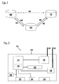
- the Fig. 1 serves in particular the representation of the data transmission between a remote maintenance module 10, an external data memory 50 and a data evaluation unit 60.
- the remote maintenance module 10 is mounted in a truck, not shown. It has a data memory 14 and an electronic control unit 12, in connection with Fig. 2 will be discussed in more detail.
- the remote maintenance module 10 is also connected to a device, not shown, for acquiring operational data or captures it itself. This operational data, controlled by the electronic control unit 12, first in the data memory 14 of the remote maintenance module 10, ie stored in the truck. At times that can be predetermined by the control unit, a wireless data transmission 40 of the operating data is taken from the data memory 14 of the remote maintenance module 10 to an external data memory 50. For example, a mobile radio network or a WLAN is used for the wireless data transmission 40. Due to the regular wireless data transmission 40, the data in the external data memory 50 is continuously updated.
- the data evaluation unit 60 which in the example is a PC, accesses this database via a data connection 42.
- This can also be realized wireless or wired.
- the data in the data memory 50 Thus, regardless of a connection to the remote maintenance module or truck are constantly available for evaluation by the data evaluation unit 60.
- the wireless data transmission 40 is initiated by the electronic control unit 12 of the remote maintenance module 10, so that no user interaction is required to keep the data in the data memory 50 up to date.
- no manual connection between the truck and the data storage 50 must be made manually, it must be no specific query the data from the memory 14 of the remote maintenance module 10 from the outside caused, and it is not necessary, the data transfer manually from the truck trigger.
- the orders may specify in detail which type of data and to what extent or at what frequency these data should be recorded and stored on the truck.
- the jobs are transmitted to the external data memory 50 by the data evaluation unit 60 as indicated by the arrow 44. They can be addressed to a specific truck.
- the electronic control unit 12 next builds a wireless data transmission 40 to the data memory 50, a corresponding order present in the data memory 50 is transmitted to the remote maintenance module 10 in the industrial truck by initiation of the control unit 12, as indicated by the arrow 46.
- the electronic control unit 12 then performs an order-based data collection. After the job has been transferred, it will be deleted in the external memory.
- the dashed arrow designated by 48 from the data evaluation unit 60 to the remote maintenance module 10 indicates that the electronic control unit 12, triggered by the data evaluation unit 60, for example via a wireless connection, eg querying an order from the memory 50, which is then transferred to the module 10.
- Fig. 2 schematically shows the structure of the truck mounted on the remote maintenance module 10 Fig. 1 ,
- the remote maintenance module 10 includes an electronic control unit 12 and a data memory 14. These are combined in the illustrated embodiment in a miniature PC.
- the miniature PC may include a CD or DVD drive, a fixed memory (flash memory), and a working memory.
- the electronic control unit 12 is connected to a mobile telephone network modem 16, to which an antenna 28 is connected.
- the modem 16 may be, for example, a UMTS, GSM and / or GPRS modem.
- a WLAN module 18 is connected to the electronic control unit 12 via another connection.
- the WLAN module 18 has an antenna 30.
- the wireless data transmission 40 can be carried out optionally with the aid of the modem 16 or with the aid of the WLAN module 18.
- the previously mentioned components of the remote maintenance module 10 are optionally arranged with the exception of the antennas 28, 30 in a common housing 32, which can be easily attached to or in an industrial truck.
- the housing 32 has a number of connectors 20 to 26, which serve to connect other components.
- the connector 20 is a connection option for a vehicle data bus, for example for a CAN bus.
- the connections 22 offer a connection possibility for a so-called SAAB plug, which can likewise be used in conjunction with a CAN bus or alternatively or additionally to the connection of further analog sensors.
- About the connector 24 can be an Ethernet connection getting produced. This allows, for example, access to the remote maintenance module 10 via a network cable, for example for testing or maintenance purposes.
- the connector 26 is used to connect a power supply that supplies all components of the remote maintenance module 10 with voltage.
- the data memory 50 responds only when the remote maintenance module or data evaluation unit 68 is active.
- the remote maintenance module 10 includes a connected to the electronic control unit 12 display 34 via which, for example, a state of the remote maintenance module 10 can be done.
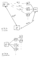
- FIG. 3 is indicated by 10.1, 10.2, etc., that a plurality of industrial trucks is provided, for example, belongs to a fleet in a logistics company.
- an intermediate memory may be arranged, with which the remote maintenance modules 10.1, 10.2, etc. communicate. The communication takes place, as described in detail above, on the initiative of the remote maintenance modules.
- the latch 51 communicates, for example via a radio link, with the external main memory 50.
- the main memory 50 can communicate with a plurality of latches 51 in different companies.
- a plurality of latches 50.1, 50.2, etc. are indicated, which communicate with an external main memory in the manner described.
- the maintenance modules 10.1, 10.2, etc. can each communicate with an intermediate memory 50.1, 50.2, etc., for example, in such a way that the data memories in the industrial trucks are connected to the battery of the industrial truck.
- the latches 50.1, 50.2, etc. are arranged in the charging station for the batteries. Once a battery is positioned in the charging station will be the vehicle's own Transfer data to the buffer in the charging station. From the charging station then in turn takes place the communication with the external main memory, as already described.
- the connection between the data memory on the battery and the buffer in the charging station is preferably carried out by radio.
Landscapes
- Engineering & Computer Science (AREA)
- Transportation (AREA)
- General Physics & Mathematics (AREA)
- Structural Engineering (AREA)
- Physics & Mathematics (AREA)
- Civil Engineering (AREA)
- Combustion & Propulsion (AREA)
- Chemical & Material Sciences (AREA)
- Life Sciences & Earth Sciences (AREA)
- Geology (AREA)
- Mechanical Engineering (AREA)
- Mobile Radio Communication Systems (AREA)
- Warehouses Or Storage Devices (AREA)
- Selective Calling Equipment (AREA)
Applications Claiming Priority (1)
| Application Number | Priority Date | Filing Date | Title |
|---|---|---|---|
| DE102007043472A DE102007043472A1 (de) | 2007-09-04 | 2007-09-04 | Flurförderzeug und Fernwartungssystem sowie Verfahren zur Fernwartung eines Flurförderzeugs |
Publications (3)
| Publication Number | Publication Date |
|---|---|
| EP2033933A2 true EP2033933A2 (fr) | 2009-03-11 |
| EP2033933A3 EP2033933A3 (fr) | 2010-06-09 |
| EP2033933B1 EP2033933B1 (fr) | 2015-08-19 |
Family
ID=40120092
Family Applications (1)
| Application Number | Title | Priority Date | Filing Date |
|---|---|---|---|
| EP08015252.3A Ceased EP2033933B1 (fr) | 2007-09-04 | 2008-08-29 | Chariot de manutention doté en particulier d'une maintenance à distance |
Country Status (4)
| Country | Link |
|---|---|
| US (1) | US20090216858A1 (fr) |
| EP (1) | EP2033933B1 (fr) |
| CN (1) | CN101417778A (fr) |
| DE (1) | DE102007043472A1 (fr) |
Cited By (12)
| Publication number | Priority date | Publication date | Assignee | Title |
|---|---|---|---|---|
| GB2460326A (en) * | 2008-05-26 | 2009-12-02 | Jungheinrich Ag | Wireless remote control of a floor conveyor |
| EP2279980A1 (fr) * | 2009-07-28 | 2011-02-02 | STILL GmbH | Chariot de manutention doté d'un dispositif de collecte de données |
| US8060400B2 (en) | 2006-12-13 | 2011-11-15 | Crown Equipment Corporation | Fleet management system |
| EP2508466A3 (fr) * | 2011-04-04 | 2012-10-24 | STILL GmbH | Chariot de manutention doté d'un dispositif de saisie de données |
| US8583314B2 (en) | 2009-08-12 | 2013-11-12 | Crown Equipment Corporation | Information system for industrial vehicles |
| EP2945215A3 (fr) * | 2014-05-14 | 2015-12-23 | STILL GmbH | Batterie de propulsion |
| EP3088350A1 (fr) * | 2015-04-30 | 2016-11-02 | BT Products AB | Procédé de détermination de l'état d'un dispositif dans un chariot élévateur à fourche |
| US9984341B2 (en) | 2006-12-13 | 2018-05-29 | Crown Equipment Corporation | Information system for industrial vehicles including cyclical recurring vehicle information message |
| US10013815B2 (en) | 2006-12-13 | 2018-07-03 | Crown Equipment Corporation | Information system for industrial vehicles |
| US10600256B2 (en) | 2006-12-13 | 2020-03-24 | Crown Equipment Corporation | Impact sensing usable with fleet management system |
| US11225404B2 (en) | 2006-12-13 | 2022-01-18 | Crown Equipment Corporation | Information system for industrial vehicles |
| US12380373B2 (en) | 2009-09-01 | 2025-08-05 | Crown Equipment Corporation | Information system for industrial vehicles including cyclical recurring vehicle information message |
Families Citing this family (2)
| Publication number | Priority date | Publication date | Assignee | Title |
|---|---|---|---|---|
| DE102016109927A1 (de) * | 2016-05-30 | 2017-11-30 | Jungheinrich Aktiengesellschaft | Vorrichtung zur Erfassung von Fahrzeugdaten |
| DE102017001517B4 (de) | 2017-02-15 | 2023-12-14 | Audi Ag | Verfahren zum Erstellen einer Zustandsanalyse einer Funknetzwerk-Infrastruktur |
Family Cites Families (19)
| Publication number | Priority date | Publication date | Assignee | Title |
|---|---|---|---|---|
| US20020101218A1 (en) * | 1984-05-21 | 2002-08-01 | Intermec Ip Corp | Battery pack having memory |
| US5457629A (en) * | 1989-01-31 | 1995-10-10 | Norand Corporation | Vehicle data system with common supply of data and power to vehicle devices |
| US5604715A (en) * | 1994-06-21 | 1997-02-18 | Aman; James A. | Automated lumber unit trucking system |
| DE19922137A1 (de) * | 1999-05-12 | 2000-11-16 | Still & Saxby Sarl | Flurförderzeug mit einem Batterieblock |
| US7656271B2 (en) * | 2002-01-09 | 2010-02-02 | I.D. Systems, Inc. | System and method for managing a remotely located asset |
| DE10015009B4 (de) * | 2000-03-20 | 2006-02-23 | Jungheinrich Ag | Flurförderzeug mit einem Anzeige-, Steuerungs- und Überwachungssystem |
| DE10150631C5 (de) * | 2001-10-12 | 2014-04-10 | Jungheinrich Aktiengesellschaft | Flurförderzeug mit Schnittstelle für Diagnosedaten |
| DE10359081A1 (de) | 2003-12-17 | 2005-07-21 | Still S.A.R.L. | Flurförderzeug mit mindestens einer elektrischen Steuerungsvorrichtung |
| US20050216227A1 (en) * | 2004-03-23 | 2005-09-29 | Jogesh Warrior | Method of operating sensor net and sensor apparatus |
| US20060158154A1 (en) * | 2005-01-18 | 2006-07-20 | Maurilus Jean R | Method and apparatus for backing up data from cell phones and other hand-held devices |
| DE102005024883A1 (de) | 2005-05-31 | 2006-12-07 | Still Gmbh | Flurförderzeug |
| DE102005046040A1 (de) * | 2005-09-27 | 2007-04-12 | Rema Lipprandt Gmbh & Co. Kg | Elektrische Steckverbindung und Verfahren zur Identifizierung eines Akkumulators |
| DE102005048762A1 (de) | 2005-10-10 | 2007-04-12 | Still Wagner Gmbh & Co Kg | Ferndiagnosesystem und Verfahren zur Ferndiagnose an einem Flurförderzeug |
| DE102006010291A1 (de) * | 2006-03-03 | 2007-09-06 | Jungheinrich Ag | Flurförderzeug mit Nutzungsdatenerfassung |
| US20070222758A1 (en) * | 2006-03-22 | 2007-09-27 | Mulcahy Michael R | Method, system, and computer peripheral for docking a handheld computer |
| DE102006014447A1 (de) * | 2006-03-29 | 2007-10-04 | Jungheinrich Aktiengesellschaft | Flurförderzeug mit einem Lasttragmittel |
| DE102006014450A1 (de) * | 2006-03-29 | 2007-10-04 | Jungheinrich Aktiengesellschaft | Flurförderzeug mit einem Datenbus und einer Sende- und Empfangseinheit |
| CA2909832C (fr) | 2006-12-13 | 2018-05-01 | Crown Equipment Corporation | Systeme de gestion de flotte |
| US20080319666A1 (en) * | 2007-06-20 | 2008-12-25 | Petrov Andrew A | System and method for geo-positioning of a mobile equipment |
-
2007
- 2007-09-04 DE DE102007043472A patent/DE102007043472A1/de not_active Withdrawn
-
2008
- 2008-08-29 EP EP08015252.3A patent/EP2033933B1/fr not_active Ceased
- 2008-09-03 US US12/203,578 patent/US20090216858A1/en not_active Abandoned
- 2008-09-04 CN CNA2008101769434A patent/CN101417778A/zh active Pending
Non-Patent Citations (4)
| Title |
|---|
| "Transparenz im Staplerfuhrpark", FACHZEITSCHRIFT HEBEZEUGE UND FÖRDERMITTEL, vol. 11, 2000, pages 576 - 577 |
| F+H FÖRDERN UND HEBEN 43, 1993, pages 685 |
| LOGISTIK UND FÖRDERTECHNIK, no. 5, 2006, pages 38 |
| LOGISTIK, no. 12, 1994, pages 34 |
Cited By (20)
| Publication number | Priority date | Publication date | Assignee | Title |
|---|---|---|---|---|
| US11225404B2 (en) | 2006-12-13 | 2022-01-18 | Crown Equipment Corporation | Information system for industrial vehicles |
| US10600256B2 (en) | 2006-12-13 | 2020-03-24 | Crown Equipment Corporation | Impact sensing usable with fleet management system |
| US8060400B2 (en) | 2006-12-13 | 2011-11-15 | Crown Equipment Corporation | Fleet management system |
| US8249910B2 (en) | 2006-12-13 | 2012-08-21 | Crown Equipment Corporation | Fleet management system |
| US12210353B2 (en) | 2006-12-13 | 2025-01-28 | Crown Equipment Corporation | Fleet management system |
| US11947361B2 (en) | 2006-12-13 | 2024-04-02 | Crown Equipment Corporation | Fleet management system |
| US11823502B2 (en) | 2006-12-13 | 2023-11-21 | Crown Equipment Corporation | Impact sensing usable with fleet management system |
| US10810521B2 (en) | 2006-12-13 | 2020-10-20 | Crown Equipment Corporation | Information system for industrial vehicles including cyclical recurring vehicle information message |
| US10599160B2 (en) | 2006-12-13 | 2020-03-24 | Crown Equipment Corporation | Fleet management system |
| US10013815B2 (en) | 2006-12-13 | 2018-07-03 | Crown Equipment Corporation | Information system for industrial vehicles |
| US9984341B2 (en) | 2006-12-13 | 2018-05-29 | Crown Equipment Corporation | Information system for industrial vehicles including cyclical recurring vehicle information message |
| GB2460326B (en) * | 2008-05-26 | 2012-08-08 | Jungheinrich Ag | System for the remote control of a floor conveyor |
| GB2460326A (en) * | 2008-05-26 | 2009-12-02 | Jungheinrich Ag | Wireless remote control of a floor conveyor |
| EP2279980A1 (fr) * | 2009-07-28 | 2011-02-02 | STILL GmbH | Chariot de manutention doté d'un dispositif de collecte de données |
| US8725345B2 (en) | 2009-08-12 | 2014-05-13 | Crown Equipment Corporation | Information system for industrial vehicles |
| US8583314B2 (en) | 2009-08-12 | 2013-11-12 | Crown Equipment Corporation | Information system for industrial vehicles |
| US12380373B2 (en) | 2009-09-01 | 2025-08-05 | Crown Equipment Corporation | Information system for industrial vehicles including cyclical recurring vehicle information message |
| EP2508466A3 (fr) * | 2011-04-04 | 2012-10-24 | STILL GmbH | Chariot de manutention doté d'un dispositif de saisie de données |
| EP2945215A3 (fr) * | 2014-05-14 | 2015-12-23 | STILL GmbH | Batterie de propulsion |
| EP3088350A1 (fr) * | 2015-04-30 | 2016-11-02 | BT Products AB | Procédé de détermination de l'état d'un dispositif dans un chariot élévateur à fourche |
Also Published As
| Publication number | Publication date |
|---|---|
| DE102007043472A1 (de) | 2009-03-05 |
| EP2033933A3 (fr) | 2010-06-09 |
| EP2033933B1 (fr) | 2015-08-19 |
| CN101417778A (zh) | 2009-04-29 |
| US20090216858A1 (en) | 2009-08-27 |
Similar Documents
| Publication | Publication Date | Title |
|---|---|---|
| EP2033933B1 (fr) | Chariot de manutention doté en particulier d'une maintenance à distance | |
| EP2225733B1 (fr) | Système de transmission de données via une liaison de transmission entre un tachygraph et un module de traitement de données et procédé de transmission de données | |
| EP3494017B1 (fr) | Système et procédé d'entretien des véhicules et utilisation d'un tel système | |
| DE4192274C2 (de) | Verfahren und System zur Fertigungssteuerung | |
| EP3172067B1 (fr) | Methode pour configurer un dispositif de pression de pneumatique | |
| DE69133312T2 (de) | Multiniveau Radiokommunikationssystem | |
| DE102006010291A1 (de) | Flurförderzeug mit Nutzungsdatenerfassung | |
| DE102014213096A1 (de) | Verbindungsgewährleistungssystem zur Fahrzeugmontage und Steuerverfahren desselben | |
| EP2095337A1 (fr) | Système de documentation du statut de pièces remplaçables embarquées dans un aéronef | |
| EP3174740B1 (fr) | Système de surveillance de pneumatique et procédé associé | |
| DE102017201040A1 (de) | Verfahren und Einrichtung zur Identifikation einer Anbauvorrichtung | |
| DE102010041294A1 (de) | Fahrzeug-Management-System | |
| DE102022131644A1 (de) | System und verfahren für einen kaufberater für gebrauchte batterieelektrofahrzeuge (bev) | |
| DE102013006070A1 (de) | Verfahren und Vorrichtung zur Übermittlung fahrzeugspezifischer Informationen an ein Endgerät eines Nutzers durch Mittel der drahtlosen Kommunikation | |
| EP2508466A2 (fr) | Chariot de manutention doté d'un dispositif de saisie de données | |
| EP3493175B1 (fr) | Procédé de couplage d'une seconde unité de commande à distance avec une première unité de commande | |
| EP2080731B1 (fr) | Chariot de manutention doté d'au moins un transpondeur RFID | |
| DE102005024883A1 (de) | Flurförderzeug | |
| DE102010022857A1 (de) | Ereignisgesteuerte Telematikeinheit zur Überwachung eines Ladungsträgers und Verfahren zum Betrieb der Telematikeinheit | |
| EP2467835B1 (fr) | Appareil de contrôle | |
| DE102014009519A1 (de) | Vorrichtung und Verfahren zur Bereitstellung zumindest einer fahrzeugspezifischen Information | |
| WO2011154267A2 (fr) | Procédé pour surveiller l'état de fonctionnement d'un véhicule, notamment d'un véhicule électrique ou hybride | |
| DE102013223925A1 (de) | System und Verfahren zum effizienten Betreiben von Transportfahrzeugen | |
| EP2992501A1 (fr) | Système d'information et procédé de traitement de l'information, en particulier pour assister des travaux dans un atelier de réparation automobile | |
| EP3314954B1 (fr) | Procédé pour faire fonctionner un appareil d'outillage |
Legal Events
| Date | Code | Title | Description |
|---|---|---|---|
| PUAI | Public reference made under article 153(3) epc to a published international application that has entered the european phase |
Free format text: ORIGINAL CODE: 0009012 |
|
| AK | Designated contracting states |
Kind code of ref document: A2 Designated state(s): AT BE BG CH CY CZ DE DK EE ES FI FR GB GR HR HU IE IS IT LI LT LU LV MC MT NL NO PL PT RO SE SI SK TR |
|
| AX | Request for extension of the european patent |
Extension state: AL BA MK RS |
|
| PUAL | Search report despatched |
Free format text: ORIGINAL CODE: 0009013 |
|
| AK | Designated contracting states |
Kind code of ref document: A3 Designated state(s): AT BE BG CH CY CZ DE DK EE ES FI FR GB GR HR HU IE IS IT LI LT LU LV MC MT NL NO PL PT RO SE SI SK TR |
|
| AX | Request for extension of the european patent |
Extension state: AL BA MK RS |
|
| 17P | Request for examination filed |
Effective date: 20101208 |
|
| AKX | Designation fees paid |
Designated state(s): DE FR GB IT SE |
|
| 17Q | First examination report despatched |
Effective date: 20111014 |
|
| GRAP | Despatch of communication of intention to grant a patent |
Free format text: ORIGINAL CODE: EPIDOSNIGR1 |
|
| INTG | Intention to grant announced |
Effective date: 20150310 |
|
| GRAS | Grant fee paid |
Free format text: ORIGINAL CODE: EPIDOSNIGR3 |
|
| GRAA | (expected) grant |
Free format text: ORIGINAL CODE: 0009210 |
|
| AK | Designated contracting states |
Kind code of ref document: B1 Designated state(s): DE FR GB IT SE |
|
| REG | Reference to a national code |
Ref country code: GB Ref legal event code: FG4D Free format text: NOT ENGLISH |
|
| REG | Reference to a national code |
Ref country code: FR Ref legal event code: PLFP Year of fee payment: 8 |
|
| REG | Reference to a national code |
Ref country code: DE Ref legal event code: R096 Ref document number: 502008013281 Country of ref document: DE |
|
| PG25 | Lapsed in a contracting state [announced via postgrant information from national office to epo] |
Ref country code: SE Free format text: LAPSE BECAUSE OF FAILURE TO SUBMIT A TRANSLATION OF THE DESCRIPTION OR TO PAY THE FEE WITHIN THE PRESCRIBED TIME-LIMIT Effective date: 20150819 |
|
| PG25 | Lapsed in a contracting state [announced via postgrant information from national office to epo] |
Ref country code: IT Free format text: LAPSE BECAUSE OF FAILURE TO SUBMIT A TRANSLATION OF THE DESCRIPTION OR TO PAY THE FEE WITHIN THE PRESCRIBED TIME-LIMIT Effective date: 20150819 |
|
| REG | Reference to a national code |
Ref country code: DE Ref legal event code: R026 Ref document number: 502008013281 Country of ref document: DE |
|
| PLBI | Opposition filed |
Free format text: ORIGINAL CODE: 0009260 |
|
| PLAX | Notice of opposition and request to file observation + time limit sent |
Free format text: ORIGINAL CODE: EPIDOSNOBS2 |
|
| 26 | Opposition filed |
Opponent name: TOYOTA MATERIAL HANDLING MANUFACTURING SWEDEN AB Effective date: 20160519 Opponent name: STILL GMBH Effective date: 20160519 |
|
| REG | Reference to a national code |
Ref country code: FR Ref legal event code: PLFP Year of fee payment: 9 |
|
| PLAF | Information modified related to communication of a notice of opposition and request to file observations + time limit |
Free format text: ORIGINAL CODE: EPIDOSCOBS2 |
|
| PLBP | Opposition withdrawn |
Free format text: ORIGINAL CODE: 0009264 |
|
| PLBP | Opposition withdrawn |
Free format text: ORIGINAL CODE: 0009264 |
|
| PLBB | Reply of patent proprietor to notice(s) of opposition received |
Free format text: ORIGINAL CODE: EPIDOSNOBS3 |
|
| PLBD | Termination of opposition procedure: decision despatched |
Free format text: ORIGINAL CODE: EPIDOSNOPC1 |
|
| REG | Reference to a national code |
Ref country code: DE Ref legal event code: R100 Ref document number: 502008013281 Country of ref document: DE |
|
| PLAB | Opposition data, opponent's data or that of the opponent's representative modified |
Free format text: ORIGINAL CODE: 0009299OPPO |
|
| PLBM | Termination of opposition procedure: date of legal effect published |
Free format text: ORIGINAL CODE: 0009276 |
|
| STAA | Information on the status of an ep patent application or granted ep patent |
Free format text: STATUS: OPPOSITION PROCEDURE CLOSED |
|
| 27C | Opposition proceedings terminated |
Effective date: 20170129 |
|
| REG | Reference to a national code |
Ref country code: FR Ref legal event code: PLFP Year of fee payment: 10 |
|
| PGFP | Annual fee paid to national office [announced via postgrant information from national office to epo] |
Ref country code: GB Payment date: 20170830 Year of fee payment: 10 Ref country code: FR Payment date: 20170828 Year of fee payment: 10 |
|
| PGFP | Annual fee paid to national office [announced via postgrant information from national office to epo] |
Ref country code: DE Payment date: 20171030 Year of fee payment: 10 |
|
| REG | Reference to a national code |
Ref country code: DE Ref legal event code: R119 Ref document number: 502008013281 Country of ref document: DE |
|
| GBPC | Gb: european patent ceased through non-payment of renewal fee |
Effective date: 20180829 |
|
| PG25 | Lapsed in a contracting state [announced via postgrant information from national office to epo] |
Ref country code: DE Free format text: LAPSE BECAUSE OF NON-PAYMENT OF DUE FEES Effective date: 20190301 |
|
| PG25 | Lapsed in a contracting state [announced via postgrant information from national office to epo] |
Ref country code: FR Free format text: LAPSE BECAUSE OF NON-PAYMENT OF DUE FEES Effective date: 20180831 |
|
| PG25 | Lapsed in a contracting state [announced via postgrant information from national office to epo] |
Ref country code: GB Free format text: LAPSE BECAUSE OF NON-PAYMENT OF DUE FEES Effective date: 20180829 |