EP2034120A2 - Ausrüstung für Feuerschutzabschlüsse - Google Patents
Ausrüstung für Feuerschutzabschlüsse Download PDFInfo
- Publication number
- EP2034120A2 EP2034120A2 EP08405218A EP08405218A EP2034120A2 EP 2034120 A2 EP2034120 A2 EP 2034120A2 EP 08405218 A EP08405218 A EP 08405218A EP 08405218 A EP08405218 A EP 08405218A EP 2034120 A2 EP2034120 A2 EP 2034120A2
- Authority
- EP
- European Patent Office
- Prior art keywords
- frame
- fire
- door
- foam
- fire protection
- Prior art date
- Legal status (The legal status is an assumption and is not a legal conclusion. Google has not performed a legal analysis and makes no representation as to the accuracy of the status listed.)
- Granted
Links
- 239000000463 material Substances 0.000 claims abstract description 69
- 239000006260 foam Substances 0.000 claims abstract description 36
- 239000000779 smoke Substances 0.000 claims abstract description 11
- 239000003380 propellant Substances 0.000 claims description 10
- 239000004814 polyurethane Substances 0.000 claims description 7
- 239000000443 aerosol Substances 0.000 claims description 6
- SCVFZCLFOSHCOH-UHFFFAOYSA-M potassium acetate Chemical compound [K+].CC([O-])=O SCVFZCLFOSHCOH-UHFFFAOYSA-M 0.000 claims description 6
- 239000000203 mixture Substances 0.000 claims description 5
- 239000004593 Epoxy Substances 0.000 claims description 4
- BPQQTUXANYXVAA-UHFFFAOYSA-N Orthosilicate Chemical compound [O-][Si]([O-])([O-])[O-] BPQQTUXANYXVAA-UHFFFAOYSA-N 0.000 claims description 4
- NIXOWILDQLNWCW-UHFFFAOYSA-N acrylic acid group Chemical group C(C=C)(=O)O NIXOWILDQLNWCW-UHFFFAOYSA-N 0.000 claims description 4
- 230000000712 assembly Effects 0.000 claims description 4
- 238000000429 assembly Methods 0.000 claims description 4
- UPMLOUAZCHDJJD-UHFFFAOYSA-N 4,4'-Diphenylmethane Diisocyanate Chemical compound C1=CC(N=C=O)=CC=C1CC1=CC=C(N=C=O)C=C1 UPMLOUAZCHDJJD-UHFFFAOYSA-N 0.000 claims description 3
- OKTJSMMVPCPJKN-UHFFFAOYSA-N Carbon Chemical compound [C] OKTJSMMVPCPJKN-UHFFFAOYSA-N 0.000 claims description 3
- 229920005830 Polyurethane Foam Polymers 0.000 claims description 3
- 239000004115 Sodium Silicate Substances 0.000 claims description 3
- 150000001875 compounds Chemical class 0.000 claims description 3
- 239000010439 graphite Substances 0.000 claims description 3
- 229910002804 graphite Inorganic materials 0.000 claims description 3
- 229920005862 polyol Polymers 0.000 claims description 3
- 150000003077 polyols Chemical class 0.000 claims description 3
- 229920001296 polysiloxane Polymers 0.000 claims description 3
- 229920002635 polyurethane Polymers 0.000 claims description 3
- 235000011056 potassium acetate Nutrition 0.000 claims description 3
- NTHWMYGWWRZVTN-UHFFFAOYSA-N sodium silicate Chemical compound [Na+].[Na+].[O-][Si]([O-])=O NTHWMYGWWRZVTN-UHFFFAOYSA-N 0.000 claims description 3
- 229910052911 sodium silicate Inorganic materials 0.000 claims description 3
- KVMPUXDNESXNOH-UHFFFAOYSA-N tris(1-chloropropan-2-yl) phosphate Chemical compound ClCC(C)OP(=O)(OC(C)CCl)OC(C)CCl KVMPUXDNESXNOH-UHFFFAOYSA-N 0.000 claims description 3
- RNFJDJUURJAICM-UHFFFAOYSA-N 2,2,4,4,6,6-hexaphenoxy-1,3,5-triaza-2$l^{5},4$l^{5},6$l^{5}-triphosphacyclohexa-1,3,5-triene Chemical compound N=1P(OC=2C=CC=CC=2)(OC=2C=CC=CC=2)=NP(OC=2C=CC=CC=2)(OC=2C=CC=CC=2)=NP=1(OC=1C=CC=CC=1)OC1=CC=CC=C1 RNFJDJUURJAICM-UHFFFAOYSA-N 0.000 claims description 2
- 239000003063 flame retardant Substances 0.000 claims description 2
- 239000012948 isocyanate Substances 0.000 claims description 2
- 150000002513 isocyanates Chemical class 0.000 claims description 2
- 239000011496 polyurethane foam Substances 0.000 claims description 2
- 239000000853 adhesive Substances 0.000 claims 2
- 230000001070 adhesive effect Effects 0.000 claims 2
- 229920002323 Silicone foam Polymers 0.000 claims 1
- 230000004888 barrier function Effects 0.000 claims 1
- 239000013514 silicone foam Substances 0.000 claims 1
- 239000007789 gas Substances 0.000 description 8
- 239000004570 mortar (masonry) Substances 0.000 description 5
- 230000000694 effects Effects 0.000 description 4
- 239000000945 filler Substances 0.000 description 4
- 239000007921 spray Substances 0.000 description 4
- 230000009970 fire resistant effect Effects 0.000 description 3
- 230000004992 fission Effects 0.000 description 3
- 238000004026 adhesive bonding Methods 0.000 description 2
- 230000001419 dependent effect Effects 0.000 description 2
- 238000011161 development Methods 0.000 description 2
- 230000018109 developmental process Effects 0.000 description 2
- 238000009413 insulation Methods 0.000 description 2
- 239000007788 liquid Substances 0.000 description 2
- 230000015572 biosynthetic process Effects 0.000 description 1
- 239000003546 flue gas Substances 0.000 description 1
Images





Classifications
-
- E—FIXED CONSTRUCTIONS
- E06—DOORS, WINDOWS, SHUTTERS, OR ROLLER BLINDS IN GENERAL; LADDERS
- E06B—FIXED OR MOVABLE CLOSURES FOR OPENINGS IN BUILDINGS, VEHICLES, FENCES OR LIKE ENCLOSURES IN GENERAL, e.g. DOORS, WINDOWS, BLINDS, GATES
- E06B5/00—Doors, windows, or like closures for special purposes; Border constructions therefor
- E06B5/10—Doors, windows, or like closures for special purposes; Border constructions therefor for protection against air-raid or other war-like action; for other protective purposes
- E06B5/16—Fireproof doors or similar closures; Adaptations of fixed constructions therefor
- E06B5/164—Sealing arrangements between the door or window and its frame, e.g. intumescent seals specially adapted therefor
-
- B—PERFORMING OPERATIONS; TRANSPORTING
- B65—CONVEYING; PACKING; STORING; HANDLING THIN OR FILAMENTARY MATERIAL
- B65D—CONTAINERS FOR STORAGE OR TRANSPORT OF ARTICLES OR MATERIALS, e.g. BAGS, BARRELS, BOTTLES, BOXES, CANS, CARTONS, CRATES, DRUMS, JARS, TANKS, HOPPERS, FORWARDING CONTAINERS; ACCESSORIES, CLOSURES, OR FITTINGS THEREFOR; PACKAGING ELEMENTS; PACKAGES
- B65D83/00—Containers or packages with special means for dispensing contents
- B65D83/14—Containers for dispensing liquid or semi-liquid contents by internal gaseous pressure, i.e. aerosol containers comprising propellant
- B65D83/68—Dispensing two or more contents
- B65D83/682—Dispensing two or more contents initially separated and subsequently mixed
-
- C—CHEMISTRY; METALLURGY
- C09—DYES; PAINTS; POLISHES; NATURAL RESINS; ADHESIVES; COMPOSITIONS NOT OTHERWISE PROVIDED FOR; APPLICATIONS OF MATERIALS NOT OTHERWISE PROVIDED FOR
- C09K—MATERIALS FOR MISCELLANEOUS APPLICATIONS, NOT PROVIDED FOR ELSEWHERE
- C09K21/00—Fireproofing materials
- C09K21/14—Macromolecular materials
-
- E—FIXED CONSTRUCTIONS
- E06—DOORS, WINDOWS, SHUTTERS, OR ROLLER BLINDS IN GENERAL; LADDERS
- E06B—FIXED OR MOVABLE CLOSURES FOR OPENINGS IN BUILDINGS, VEHICLES, FENCES OR LIKE ENCLOSURES IN GENERAL, e.g. DOORS, WINDOWS, BLINDS, GATES
- E06B5/00—Doors, windows, or like closures for special purposes; Border constructions therefor
- E06B5/10—Doors, windows, or like closures for special purposes; Border constructions therefor for protection against air-raid or other war-like action; for other protective purposes
- E06B5/16—Fireproof doors or similar closures; Adaptations of fixed constructions therefor
- E06B5/161—Profile members therefor
-
- B—PERFORMING OPERATIONS; TRANSPORTING
- B65—CONVEYING; PACKING; STORING; HANDLING THIN OR FILAMENTARY MATERIAL
- B65D—CONTAINERS FOR STORAGE OR TRANSPORT OF ARTICLES OR MATERIALS, e.g. BAGS, BARRELS, BOTTLES, BOXES, CANS, CARTONS, CRATES, DRUMS, JARS, TANKS, HOPPERS, FORWARDING CONTAINERS; ACCESSORIES, CLOSURES, OR FITTINGS THEREFOR; PACKAGING ELEMENTS; PACKAGES
- B65D83/00—Containers or packages with special means for dispensing contents
- B65D83/14—Containers for dispensing liquid or semi-liquid contents by internal gaseous pressure, i.e. aerosol containers comprising propellant
- B65D83/28—Nozzles, nozzle fittings or accessories specially adapted therefor
- B65D83/30—Nozzles, nozzle fittings or accessories specially adapted therefor for guiding the flow of the dispensed content, e.g. funnels or hoods
- B65D83/303—Nozzles, nozzle fittings or accessories specially adapted therefor for guiding the flow of the dispensed content, e.g. funnels or hoods using extension tubes located in or at the nozzle outlets
Definitions
- the invention relates to an equipment for fire protection closures according to the preamble of claim 1 and a fire door arrangement according to the preamble of claim 10.
- the object of the invention is to propose equipment for fire protection shutters such as fire door assemblies and the like, which is easy to use and which makes it possible to ensure the fire safety of fire door assemblies without the door frames having to be filled with mortar , in particular, to ensure that over the frame over a longer period of time neither fire nor smoke can leave the fire room.
- the equipment comprises an intumescent material for attachment in the frame and / or on the underside of the door and a foamable filler material, in particular based on polyurethane, silicone, silicate, acrylic or an epoxy compound.
- the intumescent material that expands three-dimensionally under the effect of heat that neither fire nor smoke can leave the fire area over the frame and / or the gap existing between the underside of the door and the floor over a longer period of time.
- the intumescent material may e.g. consist of plates, tapes, strips of the roll and the like. Foams which increase their volume when exposed to heat are also understood to be intumescent materials.
- the equipment comprises a container designed as an aerosol can, which is provided with two independent, filled with different components chambers, one chamber with a first component to form a fire protection foam and the other chamber is filled with a curing of the discharged fire protection foam accelerating second component.
- a fire protection foam can be quickly, easily and safely introduced into the frame and / or mounted on the underside of the door.
- the chamber for forming the fire protection foam is, for example, a mixture of isocyanate, preferably diphenylmethane-4,4'-diisocyanate, at least one flame retardant such as tris (2-chloroisopropyl) phosphate and at least one propellant gas.
- isocyanate preferably diphenylmethane-4,4'-diisocyanate
- flame retardant such as tris (2-chloroisopropyl) phosphate
- propellant gas for example, a mixture of isocyanate, preferably diphenylmethane-4,4'-diisocyanate, at least one flame retardant such as tris (2-chloroisopropyl) phosphate and at least one propellant gas.
- the inner container is made of flexible material, it does not need to contain propellant gas.
- Another object of the invention is a frame and a pivotally mounted door comprehensive fire door assembly to propose that it is ensured that over the frame over a longer period neither fire nor smoke can leave the fire room.
- the Fig. 1 shows a schematic view of a fire door assembly according to the prior art.
- the fire door assembly comprises in addition to the actual fire door 3 a frame 1, 4 bands, a pusher 5 and a closing means. 6
- the frame 1 is bolted to the masonry 2 and mortared.
- the outer door leaf 3a is connected by means of the bands 4 with the frame 1.
- the lock with handle set 5 closes the door.
- the closing means 6 ensures the self-closing of the door.
- the outer door leaf 3a overlaps the frame 1, so that the clear passage height 7 and the clear passage width 8 results. Between the If the door bends in the event of fire, an air gap 11 is also formed on the upper side of the door 3 and the bottom 10.
- Fig. 2 shows the lower portion of the fire door assembly in a schematic section along the line AA in Fig. 1 ,
- the inner door leaf 3b rests against the frame 1.
- the insulation 12 Between the door leaves 3a and 3b, the insulation 12.
- the frame 1 is bolted to the masonry 2 and mortared.
- a closure 13 At the lower end of the door leaves 3a and 3b, a closure 13 in the form of, for example, a U-profile is attached. Between the end 13 and the bottom 10, said lower air gap 9 remains.
- Fig. 3 shows a cross section through the fire door assembly along the line BB in Fig. 1 ,
- the frame 1 is screwed by means of the tab 14 and the screw 15 with the masonry 2.
- the cavity between the frame 1 and masonry 2 is filled with mortar 16.
- the door is not shown.
- Such, trained according to the prior art fire door assembly may fire test therefore exist because the inorganic, non-combustible mortar material does not decompose and also does not form combustible gases.
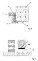
- Fig. 4 shows a cross section through the fire door assembly wherein the frame 1 is filled instead of mortar with a PU mounting foam 17.
- the organic PU material in the frame 1 has partially decomposed. There have formed gaseous components. These are about 15 minutes after the start of the test by the lower air gap 9 ( Fig. 2 ) escaped from the fire room and ignited in the air. Furthermore, it could be observed that the upper end of the frame 1 has bent. It has moved away from the masonry 2 and formed another air gap at the top. Through this flue gases have escaped. The organic PU foam had decomposed to such an extent that the frame 1 was partly hollow. In summary, one can state that the room was not completed and therefore the fire test was not passed.
- the first variant has the advantage that you can fill the frame comparatively simple, fast and inexpensive with a filler material such as a PU mounting foam, if in the frame an intumescent material is attached, especially since the intumescent ensures in case of fire that no combustible fission products, Fire or smoke can leave the room via any gap between the frame and the masonry. If an intumescent material is applied to the underside of the door, it can ensure that neither smoke nor fire can escape the fire chamber via the air gap between the underside of the door and the floor, since the intumescent material expands under heat and seals the said gap.
- a filler material such as a PU mounting foam
- intumescent material for attachment in the frame 1 and / or on the underside of the door, a material is proposed which should be under the effect of heat Volume increases or foams quickly.
- expandable graphite or a material based on sodium silicate, such as palusol (trademark of BASF)
- palusol trademark of BASF
- the intumescent material is preferably mounted circumferentially in the frame, ie both in the two vertically extending side parts as well as in the upper, horizontally extending part of the frame.
- the equipment comprises a foamable fire protection material accommodated in a container, which is received in the container in such a way that it is foamed in a dimensionally stable manner upon discharge from the container.
- a foamable fire protection material accommodated in a container, which is received in the container in such a way that it is foamed in a dimensionally stable manner upon discharge from the container.
- FIGS. 5 and 5a show possible fire protection measures on a fire door arrangement, as they can be realized by means of equipment according to the first alternative in claim 1. It shows the Fig. 5 a cross section through the masonry 2 together with the frame 1 and the Fig. 5a a longitudinal section through the masonry 2 and the bottom of the door. 3
- the frame 1 is provided with an intumescent material 18 and foamed with a conventional foam 17. On the underside of the door 3, an intumescent material 18a is also arranged.
- the Fig. 6 shows a cross section through the masonry 2 together with the frame 1, while the Fig. 6a a longitudinal section through the bottom of the door 3 shows.
- the frame 1 is filled with a fire protection foam 19.
- No additional fire protection measures were taken on the underside of door 3.
- an equipment according to the second alternative was used in claim 1, wherein the foamable fire protection material is preferably removed from a can, as described below with reference to Fig. 14 will be explained in more detail.
- the fire protection foam must prevent the burning of the frame and as little flammable Forming fission products that escape through the lower door gap 9 and could ignite.
- the Fig. 7 again shows a cross section through the masonry 2 together with the frame 1, while the Fig. 7a a longitudinal section through the bottom of the door 3 shows.
- the frame 1 is filled with a fire protection foam 19 and in addition the intumescent material 18a is mounted on the underside of the door 3.
- an equipment according to claim 3 was used.
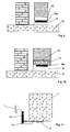
- Fig. 8 shows a cross section through the bottom of the door, which is provided with a U-shaped end 13, in which a strip of intumescent material 18a eg Blähgrafit is glued from the roll.
- This strip is in the initial state shown here, for example, 30 mm wide and 2 mm thick, for example.
- a small fire test has shown that even after 3.5 minutes, the 10 mm high air gap 9 was closed by the expanding intumescent material 18a. There are no flammable gases escaped.
- Fig. 9 shows a variant of Fig. 8 ,
- the U-profile is not open at the bottom, thereby creating a different conclusion 13.
- here is a strip-shaped intumescent material 18 a attached to the door bottom.
- Fig. 10 shows a degree 13 similar to Fig. 8 ,
- the U-profile is very large and therefore it is not enough just to install the intumescent material.
- Fig. 11 shows the frame 1, in which the intumescent material 18 is glued. After gluing the Intumeszenzmaterials 18, the frame is filled with a conventional foam mounting.
- Fig. 12 shows the frame 1 with glued Intumeszenzmaterial 18 and foamed with polyurethane foam 17.
- the intumescent material 18 has enough time to fill resulting cavities or air gaps in the frame.
- Fig. 13 shows the bottom of the door after a fire.
- the intumescent material 18a has expanded three-dimensionally under the effect of heat, so that the air gap at the bottom 9 is completely closed by the intumescent material 18a.
- FIG. 14 a preferred embodiment of a 2-K box for receiving the foamable fire protection material.
- the box is provided with two independent, filled with different components chambers 31 a, 32 a.
- the first chamber 32a is formed by the actual main can 32, in which the first, the formation of the fire protection foam serving component is received in liquid form.
- the second chamber 31a is formed by an inner container 31, in which the second, the curing of the discharged fire-resistant foam accelerating component is filled.
- This second component is preferably also liquid.
- Each chamber 31 a, 32 a of the aerosol can is connected to a closable outwardly leading outflow channel 26, 27.
- the inner container 31 is screwed to a valve plate 29.
- the valve disk 29 is provided with two valve bodies 28, 30 which serve to close the respective channel 26, 27.
- the one valve body 28 leads to the inner container 31, while the other valve body 30 opens into the main can.
- the two valve bodies 28, 30 are opened and the two partial fillings flow through the separate channels 26a, 27a in the spray head 25 into a nozzle 33, where they are brought together.
- an extended discharge pipe (not shown) are attached, which is optionally provided with mixing baffles, which favor a mixing of the two components.
- the first component for forming the fire protection foam is filled in the main can 32 mixed with a propellant gas having a critical temperature ⁇ 70 ° C.
- the second component is filled with or without propellant gas.
- a first component for example, a mixture of diphenylmethane-4,4'-diisocyanate, tris (2-chloroisopropyl) phosphate and at least one propellant gas with a critical temperature ⁇ 70 ° C is filled into the main can.
- the second, filled into the inner container 31 component may be, for example, a mixture of a polyol, potassium acetate and at least one propellant gas having a critical temperature ⁇ 70 ° C.
- the frame can be either fully or partially circumferentially provided with an intumescent material and additionally filled with a filler, in particular a foam based on polyurethane, silicone, silicate, acrylic or an epoxy compound or filled entirely with a fire-resistant fire protection foam.
- a filler in particular a foam based on polyurethane, silicone, silicate, acrylic or an epoxy compound or filled entirely with a fire-resistant fire protection foam.
- the variant with intumescent material should preferably be chosen, since the intumescent material could fill up any gap between masonry and frame. Regardless of the version realized on the frame, an intumescent material can additionally be attached to the underside of the door.
Landscapes
- Engineering & Computer Science (AREA)
- Chemical & Material Sciences (AREA)
- Civil Engineering (AREA)
- Structural Engineering (AREA)
- Materials Engineering (AREA)
- Organic Chemistry (AREA)
- Dispersion Chemistry (AREA)
- Mechanical Engineering (AREA)
- Special Wing (AREA)
- Building Environments (AREA)
Abstract

Description
- Die Erfindung betrifft eine Ausrüstung für Feuerschutzabschlüsse nach dem Oberbegriff des Anspruchs 1 sowie eine Brandschutztürenanordnung nach dem Oberbegriff des Anspruchs 10.
- Bei den nach dem Stand der Technik ausgebildeten Brandschutztürenanordnungen, welche neben der eigentlichen Tür eine Türzarge umfassen, werden die Zargen üblicherweise ausgemörtelt. Ohne Maschine ist das sehr zeitaufwändig und umständlich und darum teuer. Weil es so umständlich ist, wird in der Praxis oftmals nicht korrekt gearbeitet, die Zargen sind also mehr oder weniger hohl. Der Brandschutz ist dann nicht gegeben. Darum wäre es wünschenswert, wenn man eine Ausrüstung zur Verfügung hätte, mit welcher man die Zarge auf einfache Weise brandsicher machen könnte.
- Ausgehend von dem genannten Stand der Technik besteht die Aufgabe der Erfindung darin, eine Ausrüstung für Feuerschutzabschlüsse wie Brandschutztürenanordnungen und dergleichen vorzuschlagen, welche einfach in der Anwendung ist und welche es erlaubt, die Brandschutzsicherheit von Brandschutztürenanordnungen sicherzustellen, ohne dass die Türzargen mit Mörtel ausgefüllt werden müssen, wobei insbesondere sichergestellt werden soll, dass über die Zarge über einen längeren Zeitraum weder Feuer noch Rauch den Brandraum verlassen können.
- Diese Aufgabe wird mit einer Ausrüstung gelöst, welche eine der im Kennzeichen des Anspruchs 1 als Alternativen definierten Bestandteile umfasst.
- Bevorzugte Weiterbildungen der Ausrüstung sind in den abhängigen Ansprüchen 2 bis 9 definiert.
- So wird bei einem bevorzugten Ausführungsbeispiel vorgeschlagen, dass die Ausrüstung ein Intumeszenzmaterial zum Anbringen in der Zarge und/oder auf der Unterseite der Tür sowie ein aufschäumbares Füllmaterial, insbesondere auf der Basis von Polyurethan, Silikon, Silikat, Acryl oder einer Epoxid-Verbindung umfasst.
- Es hat sich nämlich gezeigt, dass es bei der Verwendung eines Intumeszenzmaterials genügt, den oder die verbleibenden Hohlräume ggf. mit einem herkömmlichen Füllmaterial zu füllen.
- Jedenfalls kann durch das sich unter Wärmeeinwirkung dreidimensional ausdehnende Intumeszenzmaterial sichergestellt werden, dass über die Zarge und/oder den zwischen der Unterseite der Tür und dem Boden bestehenden Spalt weder Feuer noch Rauch über einen längeren Zeitraum den Brandraum verlassen können. Das Intumeszenzmaterial kann z.B. aus Platten, Bändern, Streifen von der Rolle und dgl. bestehen. Auch Schäume, die bei Wärmeeinwirkung ihr Volumen vergrößern, werden als Intumeszenzmaterial verstanden.
- Sofern kein Intumeszenzmaterial verwendet werden soll, umfasst die Ausrüstung gemäss einem weiteren bevorzugten Ausführungsbeispiel einen als Aerosoldose ausgebildeten Behälter, der mit zwei unabhängigen, mit unterschiedlichen Komponenten gefüllten Kammern versehen ist, wobei die eine Kammer mit einer ersten Komponente zur Bildung eines Brandschutzschaums und die andere Kammer mit einer die Aushärtung des ausgetragenen Brandschutzschaums beschleunigenden zweiten Komponente gefüllt ist. Mit einer solchen Dose kann ein Brandschutzschaum schnell, einfach und sicher in die Zarge eingebracht und/oder auf der Unterseite der Tür angebracht werden.
- In der Kammer zur Bildung des Brandschutzschaums befindet sich beispielsweise eine Mischung aus Isocyanat, bevorzugt Diphenylmethan-4,4'-diisocyanat, mindestens ein Flammschutzmittel wie beispielsweise Tris(2-chlorisopropyl)-phosphat und mindestens ein Treibgas.
- In der anderen Kammer zur beschleunigten Härtung des eigentlichen Brandschutzschaums befindet sich beispielsweise ein Polyol und Kaliumazetat. Falls der Innenbehälter aus flexiblem Material gefertigt ist, muss er kein Treibgas enthalten.
- Eine weitere Aufgabe der Erfindung besteht darin, eine Zarge sowie eine schwenkbar daran gelagerte Tür umfassende Brandschutztürenanordnung vorzuschlagen, bei welcher sichergestellt ist, dass über die Zarge über einen längeren Zeitraum weder Feuer noch Rauch den Brandraum verlassen können.
- Diese Aufgabe wird mit einer Brandschutztürenanordnung gelöst, welche mit einer der alternativ im Kennzeichen des Anspruchs 10 definierten Merkmalskombinationen versehen ist.
- Bevorzugte Weiterbildungen dieser Brandschutztürenanordnung sind in den abhängigen Ansprüchen 11 bis 15 definiert.
- Die Erfindung wird nachfolgend anhand von Zeichnungen näher erläutert. Dabei zeigt:
- Fig. 1
- eine schematische Ansicht einer nach dem Stand der Technik ausgebildeten Brandschutztürenanordnung;
- Fig. 2
- die Brandschutztürenanordnung in einem Schnitt entlang der Linie A-A in
Fig. 1 ; - Fig. 3
- die Brandschutztürenanordnung in einem Schnitt entlang der Linie B-B in
Fig. 1 ; - Fig. 4
- einen Querschnitt durch eine Mauer und eine daran befestigte Zarge;
- Fig. 5 und 5a
- einen Quer- und Längsschnitt durch eine Brandschutztürenanordnung mit einer ersten möglichen Kombination von Brandschutzmassnahmen;
- Fig. 6 und 6a,
- einen Quer- und Längsschnitt durch eine Brandschutztürenanordnung mit einer zweiten möglichen Kombination von Brandschutzmassnahmen;
- Fig. 7 und 7a,
- einen Quer- und Längsschnitt durch eine Brandschutztürenanordnung mit einer dritten möglichen Kombination von Brandschutzmassnahmen;
- Fig. 8
- den unteren Abschluss einer mit einem Intumeszenzmaterial versehenen Tür;
- Fig. 9
- eine Variante der Tür gemäss
Fig. 8 ; - Fig. 10
- eine weitere Variante der Tür gemäss
Fig. 8 ; - Fig. 11
- einen Schnitt durch eine mit einem Intumeszenzmaterial versehene Türzarge;
- Fig. 12
- einen Schnitt durch eine mit einem Intumeszenzmaterial sowie einem Füllmaterial versehene Türzarge;
- Fig. 13
- den unteren Abschluss der Tür gemäss
Fig. 5 nach einem Brand. - Fig. 14
- eine zur Aufnahme eines 2-K Brandschutzmaterials ausgebildete Aerosoldose;
- Die
Fig. 1 zeigt eine schematische Ansicht einer Brandschutztürenanordnung nach dem Stand der Technik. Die Brandschutztürenanordnung umfasst neben der eigentlichen Brandschutztür 3 eine Zarge 1, Bänder 4, eine Drückergamitur 5 sowie ein Schließmittel 6. - Die Zarge 1 ist mit dem Mauerwerk 2 verschraubt und ausgemörtelt. Das äußere Türblatt 3a ist mittels den Bändern 4 mit der Zarge 1 verbunden. Das Schloss mit Drückergarnitur 5 verschließt die Tür. Das Schließmittel 6 sorgt für das Selbstschließen der Tür. Das äußere Türblatt 3a überlappt die Zarge 1, so dass sich die lichte Durchgangshöhe 7 und die lichte Durchgangsbreite 8 ergibt. Zwischen dem unteren Ende der Tür 3 und dem Boden 10 besteht ein Luftspalt 9. Falls sich die Tür im Brandfall aufbiegt, entsteht auf der Oberseite ebenfalls ein Luftspalt 11.
-
Fig. 2 zeigt den unteren Abschnitt der Brandschutztürenanordnung in einem schematischen Schnitt entlang der Linie A-A inFig. 1 . Im geschlossenen Zustand liegt das innere Türblatt 3b an der Zarge 1 an. Zwischen den Türblättern 3a und 3b ist die Dämmung 12. Die Zarge 1 ist mit dem Mauerwerk 2 verschraubt und ausgemörtelt. Am unteren Ende der Türblätter 3a und 3b ist ein Abschluss 13 in Form z.B. eines U-Profils angebracht. Zwischen dem Abschluss 13 und dem Boden 10 verbleibt der genannte untere Luftspalt 9. -
Fig. 3 zeigt einen Querschnitt durch die Brandschutztürenanordnung entlang der Linie B-B inFig. 1 . Die Zarge 1 ist mittels der Lasche 14 und der Schraube 15 mit dem Mauerwerk 2 verschraubt. Der Hohlraum zwischen Zarge 1 und Mauerwerk 2 ist mit Mörtel 16 gefüllt. Die Tür ist nicht dargestellt. Eine solche, nach dem Stand der Technik ausgebildete Brandschutztürenanordnung kann einen Brandversuch deshalb bestehen, weil sich das anorganische, nicht brennbare Mörtelmaterial nicht zersetzt und auch keine brennbaren Gase bildet. -
Fig. 4 zeigt einen Querschnitt durch die Brandschutztürenanordnung wobei die Zarge 1 anstelle von Mörtel mit einem PU-Montageschaum 17 gefüllt ist. - Ein Brandversuch mit der Befestigungsvariante nach
Fig. 4 hat ergeben, dass der Brandschutz nicht gegeben war. Nach DIN 4102 Teil 5 muss die raumabschließende Wirkung eines Feuerschutzabschlusses gewahrt bleiben. Damit ist gemeint, dass während des Brandversuchs weder Feuer noch Rauch den Brandraum verlassen dürfen. - Während des Brandes hat sich das organische PU-Material in der Zarge 1 teilweise zersetzt. Es haben sich gasförmige Bestandteile gebildet. Diese sind ca. 15 Minuten nach Versuchsbeginn durch den unteren Luftspalt 9 (
Fig. 2 ) aus dem Brandraum entwichen und haben sich an der Luft entzündet. Des weiteren konnte man beobachten, dass sich das obere Ende der Zarge 1 verbogen hat. Es hat sich vom Mauerwerk 2 wegbewegt und einen weiteren Luftspalt oben gebildet. Durch diesen sind Rauchgase entwichen. Der organische PU-Schaum hatte sich soweit zersetzt, dass die Zarge 1 zum Teil hohl war. Zusammenfassend kann man festhalten, dass der Raumabschluss nicht gegeben war und darum der Brandversuch nicht bestanden wurde. - Zur Lösung des Problems wird eine Ausrüstung vorgeschlagen, welche einfach in der Anwendung ist und mit der man die Brandschutzsicherheit einer Brandschutztürenanordnung sicherstellen kann, so dass zumindest über die Zarge keine brennbaren Spaltprodukte oder Rauch den Brandraum verlassen können. Die diesbezügliche Ausrüstung umfasst entweder
- ein Intumeszenzmaterial zum Anbringen in der Zarge und/oder auf der Unterseite der Tür sowie ein aufschäumbares Füllmaterial zum Füllen der Zarge,
oder - ein in einem Behälter aufgenommenes, aufschäumbares Brandschutzmaterial zum Füllen der Zarge, wobei das Brandschutzmaterial derart in dem Behälter aufgenommen ist, dass es beim Austragen aus dem Behälter formstabil aufgeschäumt wird.
- Die erste Variante hat den Vorteil, dass man die Zarge vergleichsweise einfach, schnell und kostengünstig mit einem Füllmaterial wie beispielsweise einem PU-Montageschaum füllen kann, wenn in der Zarge ein Intumeszenzmaterial angebracht wird, zumal das Intumeszenzmaterial im Brandfall sicherstellt, dass keine brennbaren Spaltprodukte, Feuer oder Rauch den Raum über einen allfällig entstehenden Spalt zwischen der Zarge und dem Mauerwerk verlassen können. Sofern auf der Unterseite der Tür ein Intumeszenzmaterial angebracht wird, kann dieses sicherstellen, dass über den zwischen der Unterseite der Tür und dem Boden bestehenden Luftspalt weder Rauch noch Feuer den Brandraum verlassen können, da sich das Intumeszenzmaterial unter Wärmeeinwirkung ausdehnt und den genannten Spalt abdichtet.
- Als Intumeszenzmaterial zum Anbringen in der Zarge 1 und/oder auf der Unterseite der Tür wird ein Material vorgeschlagen, welches unter Wärmeeinwirkung sein Volumen schnell vergrößert oder aufschäumt. Beispielhaft wird expandierbarer Grafit, oder ein Material auf Basis Natriumsilikat wie Palusol (Marke der Firma BASF) als Intumeszenzmaterial genannt. Das Intumeszenzmaterial wird vorzugsweise umlaufend in der Zarge angebracht, d.h. sowohl in den beiden vertikal verlaufenden Seitenteilen wie auch in dem oberen, horizontal verlaufenden Teil der Zarge.
- Bei der zweiten Variante umfasst die Ausrüstung ein in einem Behälter aufgenommenes, aufschäumbares Brandschutzmaterial, welches derart in dem Behälter aufgenommen ist, dass es beim Austragen aus dem Behälter formstabil aufgeschäumt wird. Damit kann die Zarge schnell und einfach gefüllt werden ohne dass zuvor ein Intumeszenzmaterial angebracht werden muss. Nach dem Austragen muss der Brandschutzschaum so feuerbeständig sein, dass durch die Zarge weder Feuer noch Rauch den Brandraum verlassen können.
- Die
Figuren 5 und 5a zeigen mögliche Brandschutzmassnahmen an einer Brandschutztürenanordnung, wie sie mittels einer Ausrüstung gemäss der ersten Alternative im Anspruch 1 realisierbar sind. Dabei zeigt dieFig. 5 einen Querschnitt durch das Mauerwerk 2 zusammen mit der Zarge 1 und dieFig. 5a einen Längsschnitt durch das Mauerwerk 2 sowie die Unterseite der Tür 3. - Die Zarge 1 ist mit einem Intumeszenzmaterial 18 versehen und mit einem herkömmlichen Schaum 17 ausgeschäumt. Auf der Unterseite der Tür 3 ist ebenfalls ein Intumeszenzmaterial 18a angeordnet.
- Die
Fig. 6 zeigt einen Querschnitt durch das Mauerwerk 2 zusammen mit der Zarge 1, während dieFig. 6a einen Längsschnitt durch die Unterseite der Tür 3 zeigt. Bei dieser Variante ist die Zarge 1 mit einem Brandschutzschaum 19 gefüllt. Auf der Unterseite der Tür 3 wurden keine zusätzlichen Brandschutzmassnahmen getroffen. Bei diesem Ausführungsbeispiel kam eine Ausrüstung gemäss der zweiten Alternative im Anspruch 1 zum Einsatz, wobei das aufschäumbare Brandschutzmaterial vorzugsweise einer Dose entnommen wird, wie sie nachfolgend anhand derFig. 14 noch näher erläutert wird. Der Brandschutzschaum muss dabei das Durchbrennen der Zarge verhindern und möglichst wenig brennbare Spaltprodukte bilden, die durch den unteren Türspalt 9 entweichen und sich entzünden könnten. - Die
Fig. 7 zeigt wiederum einen Querschnitt durch das Mauerwerk 2 zusammen mit der Zarge 1, während dieFig. 7a einen Längsschnitt durch die Unterseite der Tür 3 zeigt. Bei dieser Variante ist die Zarge 1 mit einem Brandschutzschaum 19 gefüllt und zusätzlich ist auf der Unterseite der Tür 3 das Intumeszenzmaterial 18a angebracht. Bei diesem Ausführungsbeispiel kam eine Ausrüstung gemäss dem Anspruch 3 zum Einsatz. -
Fig. 8 zeigt einen Querschnitt durch die Unterseite der Tür, welche mit einem U-förmigen Abschluss 13 versehen ist, in den ein Streifen aus Intumeszenzmaterial 18a z.B. Blähgrafit von der Rolle eingeklebt ist. Dieser Streifen ist im hier dargestellten Ausgangszustand z.B. 30 mm breit und z.B. 2 mm dick. Ein Kleinbrandversuch hat ergeben, dass bereits nach 3,5 Minuten der 10 mm hohe Luftspalt 9 durch das sich ausdehnende Intumeszenzmaterial 18a verschlossen wurde. Es sind keine brennbaren Gase entwichen. -
Fig. 9 zeigt eine Variante vonFig. 8 . Das U-Profil ist nicht nach unten offen, dadurch entsteht ein anderer Abschluss 13. Jedenfalls ist auch hier auf der Türunterseite ein streifenförmiges Intumeszenzmaterial 18a angebracht. -
Fig. 10 zeigt einen Abschluss 13 ähnlich zuFig. 8 . Das U-Profil ist sehr groß und darum genügt es nicht nur das Intumeszenzmaterial einzubauen. Gemäss einer weiteren Variante der Erfindung wird vorgeschlagen, das U-Profil mit z.B. PU-Montageschaum 17 auszuschäumen und auf der Unterseite wiederum ein Intumeszenzmaterial 18a anzubringen. -
Fig. 11 zeigt die Zarge 1, in die das Intumeszenzmaterial 18 eingeklebt ist. Nach dem Einkleben des Intumeszenzmaterials 18 wird die Zarge mit einem herkömmlichen Montageschaum ausgeschäumt. -
Fig. 12 zeigt die Zarge 1 mit eingeklebtem Intumeszenzmaterial 18 und ausgeschäumt mit PU-Schaum 17. Im Brandfall hat das Intumeszenzmaterial 18 genügend Zeit, um entstehende Hohlräume oder Luftspalte in der Zarge zu füllen. -
Fig. 13 zeigt die Unterseite der Tür nach einem Brand. Wie ersichtlich, hat sich das Intumeszenzmaterial 18a unter der Wärmeeinwirkung dreidimensional ausgedehnt, so dass der Luftspalt unten 9 durch das Intumeszenzmaterial 18a vollständig verschlossen wird. - Schließlich zeigt
Fig. 14 ein bevorzugtes Ausführungsbeispiel einer 2-K Dose zur Aufnahme des schäumbaren Brandschutzmaterials. Die Dose ist mit zwei unabhängigen, mit unterschiedlichen Komponenten gefüllten Kammern 31 a, 32a versehen. Die erste Kammer 32a wird durch die eigentliche Hauptdose 32 gebildet, in welcher die erste, der Bildung des Brandschutzschaums dienende Komponente in flüssiger Form aufgenommen ist. Die zweite Kammer 31a wird durch einen Innenbehälter 31 gebildet, in dem die zweite, die Aushärtung des ausgetragenen Brandschutzschaums beschleunigende Komponente eingefüllt ist. - Diese zweite Komponente ist vorzugsweise ebenfalls flüssig. Jede Kammer 31 a, 32a der Aerosoldose ist mit einem verschließbaren, nach außen führenden Ausfließkanal 26, 27 verbunden.
- Der Innenbehälter 31 ist an einem Ventilteller 29 festgeschraubt. Der Ventilteller 29 ist mit zwei Ventilkörpern 28, 30 versehen, die dem Verschließen des jeweiligen Kanals 26, 27 dienen. Der eine Ventilkörper 28 führt zum Innenbehälter 31, während der andere Ventilkörper 30 in die Hauptdose mündet. Sobald der Sprühkopf 25 der Aerosoldose nach unten gedrückt wird, werden die beiden Ventilkörper 28, 30 geöffnet und die beiden Teilfüllungen strömen durch die getrennten Kanäle 26a, 27a im Sprühkopf 25 in einen Stutzen 33, wo sie zusammengeführt werden. An diesem Stutzen 33 des Sprühkopfs 25 kann ein verlängertes Austragsrohr (nicht dargestellt) befestigt werden, welches ggf. mit Mischschikanen versehen ist, die ein Durchmischen der beiden Komponenten begünstigen.
- Die erste Komponente zur Bildung des Brandschutzschaums ist in die Hauptdose 32 gemischt mit einem Treibgas mit einer kritischen Temperatur ≥ 70°C gefüllt. In den starren oder flexiblen Innenbehälter 31 ist die zweite Komponente mit oder ohne Treibgas gefüllt. Als erste Komponente ist beispielsweise eine Mischung aus Diphenylmethan-4,4'-diisocyanat, Tris(2-chlorisopropyl)-phosphat und mindestens ein Treibgas mit einer kritischen Temperatur ≥ 70°C in die Hauptdose abgefüllt. Die zweite, in den Innenbehälter 31 abgefüllte Komponente kann beispielsweise eine Mischung aus einem Polyol, Kaliumazetat und mindestens einem Treibgas mit einer kritischen Temperatur ≥ 70°C sein.
- Zusammenfassend lässt sich festhalten, dass verschiedene Varianten von Brandschutzmassnahmen zum Ziel führen können. So kann die Zarge entweder voll-oder teilweise umlaufend mit einem Intumeszenzmaterial versehen und zusätzlich mit einem Füllmaterial, insbesondere einem Schaum auf der Basis von Polyurethan, Silikon, Silikat, Acryl oder einer Epoxid-Verbindung gefüllt oder gänzlich mit einem feuerfesten Brandschutzschaum ausgefüllt werden. Jedenfalls kann durch beide Maßnahmen sichergestellt werden, dass im Brandfall weder Feuer noch Rauch den Brandraum verlassen kann.
- Sofern sich die Zarge unter Wärmeeinwirkung verbiegen könnte, sollte vorzugsweise die Variante mit Intumeszenzmaterial gewählt werden, da das Intumeszenzmaterial einen allenfalls entstehenden Spalt zwischen Mauerwerk und Zarge ausfüllen könnte. Unabhängig von der an der Zarge realisierten Variante kann zusätzlich auch noch auf der Unterseite der Tür ein Intumeszenzmaterial angebracht werden.
- Ggf. sind natürlich auch Kombinationen möglich, indem beispielsweise ein Intumeszenzmaterial in die Zarge eingeklebt und letztere danach mit einem Brandschutzschaum gefüllt wird.
-
- 1
- Zarge
- 2
- Mauerwerk
- 3
- Tür
- 3a
- Türblatt außen
- 3b
- Türblatt innen
- 4
- Band
- 5
- Schloss mit Drückergamitur
- 6
- Schließmittel
- 7
- lichte Durchgangshöhe
- 8
- lichte Durchgangsbreite
- 9
- Luftspalt unten
- 10
- Boden
- 11
- Luftspalt oben
- 12
- Dämmung
- 13
- Abschluss
- 14
- Lasche
- 15
- Schraube
- 16
- Mörtel
- 17
- PU-Schaum
- 18
- Intumeszenzmaterial (Mauer) / 18a Intumeszenzmaterial (Tür)
- 19
- Brandschutzschaum
- 24
- Dose
- 25
- Sprühkopf
- 26 / 26a
- Kanal
- 27 / 27a
- Kanal
- 28
- Ventilkörper
- 29
- Ventilteller
- 30
- Ventilkörper
- 31
- Innenbehälter / Kammer 31 a
- 32
- Hauptdose / Kammer 32a
- 33
- Stutzen
Claims (15)
- Ausrüstung für Feuerschutzabschlüsse insbesondere Brandschutztürenanordnungen, welche letztere eine Zarge (1) und eine schwenkbar daran gelagerte Tür (3) umfassen, wobei die Brandschutztürenanordnung im Brandfall verhindern soll, dass weder Feuer noch Rauch den Brandraum verlässt, dadurch gekennzeichnet, dass die Ausrüstung entweder- ein Intumeszenzmaterial (18, 18a) zum Anbringen in der Zarge (1) und/oder auf der Unterseite der Tür (3) sowie einen Behälter mit einem aufschäumbaren Füllmaterial (17) zum Füllen der Zarge (1),
oder- einen Behälter (24) mit einem aufschäumbaren Brandschutzmaterial (19) zum Füllen der Zarge (1) aufweist, wobei das Brandschutzmaterial derart in dem Behälter (24) aufgenommen ist, dass es beim Austragen aus dem Behälter formstabil aufgeschäumt wird. - Ausrüstung nach Anspruch 1, dadurch gekennzeichnet, dass die Ausrüstung ein Intumeszenzmaterial (18, 18a) zum Anbringen in der Zarge (1) und/oder auf der Unterseite der Tür (3) sowie ein aufschäumbares Füllmaterial (17), insbesondere auf der Basis von Polyurethan, Silikon, Silikat, Acryl oder einer Epoxid-Verbindung umfasst.
- Ausrüstung nach Anspruch 1, dadurch gekennzeichnet, dass die Ausrüstung ein in einem Behälter (24) aufgenommenes, aufschäumbares Brandschutzmaterial (19) zum Füllen der Zarge (1) sowie ein Intumeszenzmaterial (18a) zum Anbringen auf der Unterseite der Tür (3) umfasst.
- Ausrüstung nach Anspruch 1 oder 3, dadurch gekennzeichnet, dass die Ausrüstung einen als Aerosoldose (24) ausgebildeten Behälter umfasst, der mit zwei unabhängigen, mit unterschiedlichen Komponenten gefüllten Kammern (31a, 32a) versehen ist, wobei die eine Kammer (32a) mit einer ersten Komponente zur Bildung des Brandschutzschaums und die andere Kammer (31a) mit einer die Aushärtung des ausgetragenen Brandschutzschaums beschleunigenden zweiten Komponente gefüllt ist.
- Ausrüstung nach Anspruch 4, dadurch gekennzeichnet, dass jede Kammer (31 a, 32a) der Aerosoldose (24) mit einem verschließbaren, nach außen führenden Ausfließkanal (26, 27) verbunden ist.
- Ausrüstung nach Anspruch 4 oder 5, dadurch gekennzeichnet, dass die erste Komponente zur Bildung des Brandschutzschaums (19) in eine Hauptdose (32) gemischt mit einem Treibgas bevorzugt mit einer kritischen Temperatur ≥ 70°C gefüllt ist, und dass in einen starren oder flexiblen Innenbehälter (31) die zweite Komponente mit oder ohne Treibgas gefüllt ist.
- Ausrüstung nach einem der Ansprüche 4 bis 5, dadurch gekennzeichnet, dass in der Hauptdose (32) wenigstens eine Mischung aus Isocyanat, insbesondere Diphenylmethan-4,4'-diisocyanat, ein Flammschutzmittel, insbesondere Tris(2-chlorisopropyl)-phosphat und mindestens ein Treibgas bevorzugt mit einer kritischen Temperatur ≥ 70°C abgefüllt ist, und dass in dem Innenbehälter (31) wenigstens eine Mischung aus einem Polyol, Kaliumazetat und mindestens einem Treibgas bevorzugt mit einer kritischen Temperatur ≥ 70°C abgefüllt ist.
- Ausrüstung nach Anspruch 2, dadurch gekennzeichnet, dass das Intumeszenzmaterial (18, 18a) expandierbarer Grafit, Natriumsilikat oder Palusol™ ist.
- Ausrüstung nach Anspruch 8, dadurch gekennzeichnet, dass das Intumeszenzmaterial (18a, 18a) mechanisch oder mittels Klebstoff in der Zarge (1) und/oder auf der Unterseite der Tür (3) befestigbar ist.
- Brandschutztürenanordnung umfassend eine Zarge (1) und eine schwenkbar daran gelagerte Tür (3), dadurch gekennzeichnet, dass entweder in der Zarge (1) und/oder auf der Unterseite der Tür (3) ein Intumeszenzmaterial (18, 18a) angebracht und die Zarge (1) mit einem Füllmaterial (17) gefüllt ist, oder die Zarge (1) mit einem formstabilen Brandschutzschaum (19) ausgefüllt ist.
- Brandschutztürenanordnung nach Anspruch 10, dadurch gekennzeichnet, dass auf der Unterseite der Tür (3) und/oder umlaufend in der Zarge (1) ein Intumeszenzmaterial (18, 18a) angebracht ist, und dass die Zarge (1) zudem mit einem Schaum (17) gefüllt ist.
- Brandschutztürenanordnung nach Anspruch 10 oder 11, dadurch gekennzeichnet, dass das Intumeszenzmaterial (18, 18a) expandierbarer Grafit, Natriumsilikat oder Palusol (Marke der Firma BASF) ist.
- Brandschutztürenanordnung nach einem der Ansprüche 10 bis 12, dadurch gekennzeichnet, dass das Intumeszenzmaterial (18, 18a) mechanisch oder mittels Klebstoff in der Zarge (1) und/oder auf der Unterseite der Tür (3) befestigt ist.
- Ausrüstung nach einem der Ansprüche 10 bis 13, dadurch gekennzeichnet, dass das Intumeszenzmaterial (18, 18a) schaumartig ist.
- Brandschutztürenanordnung nach einem der Ansprüche 10 bis 14, dadurch gekennzeichnet, dass die Zarge (1) mit einem Füllmaterial (17) auf der Basis eines organischen Polyurethan-Schaums, eines 2K-Colux Zargen-Brandschutzschaums, eines Silikonschaums, eines Silikatschaums, eines Acrylschaums oder eines Epoxidschaums gefüllt ist.
Applications Claiming Priority (1)
| Application Number | Priority Date | Filing Date | Title |
|---|---|---|---|
| DE200710042657 DE102007042657A1 (de) | 2007-09-10 | 2007-09-10 | Ausrüstung für Feuerschutzabschlüsse |
Publications (3)
| Publication Number | Publication Date |
|---|---|
| EP2034120A2 true EP2034120A2 (de) | 2009-03-11 |
| EP2034120A3 EP2034120A3 (de) | 2012-04-04 |
| EP2034120B1 EP2034120B1 (de) | 2015-07-29 |
Family
ID=40220024
Family Applications (1)
| Application Number | Title | Priority Date | Filing Date |
|---|---|---|---|
| EP08405218.2A Not-in-force EP2034120B1 (de) | 2007-09-10 | 2008-09-08 | Ausrüstung für Feuerschutzabschlüsse |
Country Status (2)
| Country | Link |
|---|---|
| EP (1) | EP2034120B1 (de) |
| DE (1) | DE102007042657A1 (de) |
Cited By (2)
| Publication number | Priority date | Publication date | Assignee | Title |
|---|---|---|---|---|
| GB2581201A (en) * | 2019-02-11 | 2020-08-12 | Rutland Trading Company Ltd | Improvements in or relating to fire-rated door sets |
| EP3717542B1 (de) | 2017-11-27 | 2022-03-16 | Sika Technology AG | Zweikomponenten-aerosoldose |
Family Cites Families (8)
| Publication number | Priority date | Publication date | Assignee | Title |
|---|---|---|---|---|
| DE3373455D1 (en) | 1982-11-30 | 1987-10-15 | Ladoco Ag | Pressurised container for gases, liquids, pasty products or the like |
| DE3404221A1 (de) * | 1984-02-07 | 1985-08-08 | Lentia GmbH Chem. u. pharm. Erzeugnisse - Industriebedarf, 8000 München | Verfahren zur im brandfall wirksamen abdichtung von oeffnungen in bauteilen |
| FR2701286B1 (fr) * | 1993-02-08 | 1995-04-07 | Decayeux Ets | Bâti dormant de porte rapporté, comprenant des moyens coupe-feu perfectionnés. |
| DE19842614A1 (de) * | 1998-09-17 | 2000-04-20 | Theo Schroeders | Dichtungseinrichtung |
| DE19937835A1 (de) * | 1999-08-13 | 2001-03-15 | Techno Elementebau Leipzig Gmb | Feuerschutzsystem |
| CA2441246A1 (en) * | 2002-09-23 | 2004-03-23 | Hilti Aktiengesellschaft | Two-component foam system for producing constructional foams and their use |
| DE202007002712U1 (de) * | 2007-02-21 | 2007-05-10 | Klarer & Zwicky Ag | Isoliertüre mit Brandschutzeigenschaften für Kühlräume oder Tiefkühlräume |
| DE102007010903A1 (de) * | 2007-03-06 | 2008-09-18 | Deventer Profile Gmbh & Co. Kg | Elastomeres Dichtungsprofil für Türschwellendichtung |
-
2007
- 2007-09-10 DE DE200710042657 patent/DE102007042657A1/de not_active Withdrawn
-
2008
- 2008-09-08 EP EP08405218.2A patent/EP2034120B1/de not_active Not-in-force
Cited By (2)
| Publication number | Priority date | Publication date | Assignee | Title |
|---|---|---|---|---|
| EP3717542B1 (de) | 2017-11-27 | 2022-03-16 | Sika Technology AG | Zweikomponenten-aerosoldose |
| GB2581201A (en) * | 2019-02-11 | 2020-08-12 | Rutland Trading Company Ltd | Improvements in or relating to fire-rated door sets |
Also Published As
| Publication number | Publication date |
|---|---|
| EP2034120B1 (de) | 2015-07-29 |
| DE102007042657A1 (de) | 2009-03-12 |
| EP2034120A3 (de) | 2012-04-04 |
Similar Documents
| Publication | Publication Date | Title |
|---|---|---|
| EP2520337B1 (de) | Feuerhemmender Abschluss | |
| DE2742665A1 (de) | Feuerhemmende schwing- oder pendeltuer | |
| WO2018153662A1 (de) | Brandschutzelement | |
| EP2760654B1 (de) | Verfahren zum ausschäumen von hohlkammerprofilen zur herstellung von fenstern und/oder türen | |
| EP2034120B1 (de) | Ausrüstung für Feuerschutzabschlüsse | |
| DE3541442C2 (de) | ||
| EP1967684A2 (de) | Elastomeres Dichtungsprofil für Türschwellendichtung | |
| WO1983003552A1 (fr) | Barriere coupe-feu pour traversees de tuyaux | |
| DE3943165A1 (de) | Vorrichtung zum herstellen und wiederverschliessen von oeffnungen in elastischen baustoffen | |
| DE102011053560A1 (de) | Brandschutzsystem sowie Brandschutztür, Brandschutz-Wandelement und Brandschutzplatte hierfür | |
| EP3586049A1 (de) | Brandschutzelement | |
| DE9003159U1 (de) | Brandschutzklappe | |
| DE102008031364A1 (de) | Zarge | |
| DE102018125362A1 (de) | Mehrkammerhohlprofil für Brandschutztüren oder -fenster und Verfahren sowie Vorrichtung zum Herstellen eines solchen Mehrkammerhohlprofils | |
| DE3140043C2 (de) | Brandschutzklappe | |
| DE102011083084A1 (de) | Hilfsmittel zur Applikation von aufschäumenden Materialien | |
| EP1387020A2 (de) | Revisionsklappe | |
| DE19912672C2 (de) | Türblatt einer Feuerschutztür | |
| DE202008015386U1 (de) | Wärmedämmendes Element zur Wärmedämmung eines Hohlraumes | |
| DE4339636C1 (de) | Schottvorrichtung für eine Mauer | |
| DE202014103350U1 (de) | Zarge für Brandschutztüren | |
| DE102013112338A1 (de) | Dämmelement | |
| DE4131146C1 (de) | ||
| DE4326759A1 (de) | Brandschutzeinrichtung zur Abschottung eines Luftweges | |
| EP0333982A1 (de) | Durchführung für Leitungen, wie Kabel Rohre oder dergl. durch eine Wandöffnung |
Legal Events
| Date | Code | Title | Description |
|---|---|---|---|
| PUAI | Public reference made under article 153(3) epc to a published international application that has entered the european phase |
Free format text: ORIGINAL CODE: 0009012 |
|
| AK | Designated contracting states |
Kind code of ref document: A2 Designated state(s): AT BE BG CH CY CZ DE DK EE ES FI FR GB GR HR HU IE IS IT LI LT LU LV MC MT NL NO PL PT RO SE SI SK TR |
|
| AX | Request for extension of the european patent |
Extension state: AL BA MK RS |
|
| RIC1 | Information provided on ipc code assigned before grant |
Ipc: B65D 83/68 20060101ALI20111026BHEP Ipc: E06B 5/16 20060101AFI20111026BHEP Ipc: B65D 83/14 20060101ALI20111026BHEP Ipc: C09K 3/30 20060101ALI20111026BHEP Ipc: C09K 21/14 20060101ALI20111026BHEP |
|
| PUAL | Search report despatched |
Free format text: ORIGINAL CODE: 0009013 |
|
| AK | Designated contracting states |
Kind code of ref document: A3 Designated state(s): AT BE BG CH CY CZ DE DK EE ES FI FR GB GR HR HU IE IS IT LI LT LU LV MC MT NL NO PL PT RO SE SI SK TR |
|
| AX | Request for extension of the european patent |
Extension state: AL BA MK RS |
|
| RIC1 | Information provided on ipc code assigned before grant |
Ipc: B65D 83/68 20060101ALI20120228BHEP Ipc: C09K 3/30 20060101ALI20120228BHEP Ipc: C09K 21/14 20060101ALI20120228BHEP Ipc: E06B 5/16 20060101AFI20120228BHEP Ipc: B65D 83/14 20060101ALI20120228BHEP |
|
| 17P | Request for examination filed |
Effective date: 20120808 |
|
| 17Q | First examination report despatched |
Effective date: 20120920 |
|
| AKX | Designation fees paid |
Designated state(s): AT BE BG CH CY CZ DE DK EE ES FI FR GB GR HR HU IE IS IT LI LT LU LV MC MT NL NO PL PT RO SE SI SK TR |
|
| RIC1 | Information provided on ipc code assigned before grant |
Ipc: E06B 5/16 20060101ALI20141217BHEP Ipc: C09K 21/14 20060101ALI20141217BHEP Ipc: B65D 83/30 20060101ALN20141217BHEP Ipc: B65D 83/68 20060101AFI20141217BHEP Ipc: B65D 83/14 20060101ALI20141217BHEP |
|
| REG | Reference to a national code |
Ref country code: DE Ref legal event code: R079 Ref document number: 502008013191 Country of ref document: DE Free format text: PREVIOUS MAIN CLASS: E06B0005160000 Ipc: B65D0083680000 |
|
| GRAP | Despatch of communication of intention to grant a patent |
Free format text: ORIGINAL CODE: EPIDOSNIGR1 |
|
| INTG | Intention to grant announced |
Effective date: 20150304 |
|
| RIC1 | Information provided on ipc code assigned before grant |
Ipc: E06B 5/16 20060101ALI20150224BHEP Ipc: C09K 21/14 20060101ALI20150224BHEP Ipc: B65D 83/14 20060101ALI20150224BHEP Ipc: B65D 83/68 20060101AFI20150224BHEP Ipc: B65D 83/30 20060101ALN20150224BHEP |
|
| GRAS | Grant fee paid |
Free format text: ORIGINAL CODE: EPIDOSNIGR3 |
|
| GRAA | (expected) grant |
Free format text: ORIGINAL CODE: 0009210 |
|
| AK | Designated contracting states |
Kind code of ref document: B1 Designated state(s): AT BE BG CH CY CZ DE DK EE ES FI FR GB GR HR HU IE IS IT LI LT LU LV MC MT NL NO PL PT RO SE SI SK TR |
|
| REG | Reference to a national code |
Ref country code: GB Ref legal event code: FG4D Free format text: NOT ENGLISH |
|
| REG | Reference to a national code |
Ref country code: CH Ref legal event code: EP |
|
| REG | Reference to a national code |
Ref country code: AT Ref legal event code: REF Ref document number: 739073 Country of ref document: AT Kind code of ref document: T Effective date: 20150815 |
|
| REG | Reference to a national code |
Ref country code: IE Ref legal event code: FG4D Free format text: LANGUAGE OF EP DOCUMENT: GERMAN |
|
| REG | Reference to a national code |
Ref country code: DE Ref legal event code: R096 Ref document number: 502008013191 Country of ref document: DE |
|
| REG | Reference to a national code |
Ref country code: LT Ref legal event code: MG4D |
|
| REG | Reference to a national code |
Ref country code: NL Ref legal event code: MP Effective date: 20150729 |
|
| PG25 | Lapsed in a contracting state [announced via postgrant information from national office to epo] |
Ref country code: NO Free format text: LAPSE BECAUSE OF FAILURE TO SUBMIT A TRANSLATION OF THE DESCRIPTION OR TO PAY THE FEE WITHIN THE PRESCRIBED TIME-LIMIT Effective date: 20151029 Ref country code: LV Free format text: LAPSE BECAUSE OF FAILURE TO SUBMIT A TRANSLATION OF THE DESCRIPTION OR TO PAY THE FEE WITHIN THE PRESCRIBED TIME-LIMIT Effective date: 20150729 Ref country code: LT Free format text: LAPSE BECAUSE OF FAILURE TO SUBMIT A TRANSLATION OF THE DESCRIPTION OR TO PAY THE FEE WITHIN THE PRESCRIBED TIME-LIMIT Effective date: 20150729 Ref country code: FI Free format text: LAPSE BECAUSE OF FAILURE TO SUBMIT A TRANSLATION OF THE DESCRIPTION OR TO PAY THE FEE WITHIN THE PRESCRIBED TIME-LIMIT Effective date: 20150729 Ref country code: GR Free format text: LAPSE BECAUSE OF FAILURE TO SUBMIT A TRANSLATION OF THE DESCRIPTION OR TO PAY THE FEE WITHIN THE PRESCRIBED TIME-LIMIT Effective date: 20151030 |
|
| PG25 | Lapsed in a contracting state [announced via postgrant information from national office to epo] |
Ref country code: HR Free format text: LAPSE BECAUSE OF FAILURE TO SUBMIT A TRANSLATION OF THE DESCRIPTION OR TO PAY THE FEE WITHIN THE PRESCRIBED TIME-LIMIT Effective date: 20150729 Ref country code: SE Free format text: LAPSE BECAUSE OF FAILURE TO SUBMIT A TRANSLATION OF THE DESCRIPTION OR TO PAY THE FEE WITHIN THE PRESCRIBED TIME-LIMIT Effective date: 20150729 Ref country code: IS Free format text: LAPSE BECAUSE OF FAILURE TO SUBMIT A TRANSLATION OF THE DESCRIPTION OR TO PAY THE FEE WITHIN THE PRESCRIBED TIME-LIMIT Effective date: 20151129 Ref country code: PT Free format text: LAPSE BECAUSE OF FAILURE TO SUBMIT A TRANSLATION OF THE DESCRIPTION OR TO PAY THE FEE WITHIN THE PRESCRIBED TIME-LIMIT Effective date: 20151130 Ref country code: PL Free format text: LAPSE BECAUSE OF FAILURE TO SUBMIT A TRANSLATION OF THE DESCRIPTION OR TO PAY THE FEE WITHIN THE PRESCRIBED TIME-LIMIT Effective date: 20150729 Ref country code: ES Free format text: LAPSE BECAUSE OF FAILURE TO SUBMIT A TRANSLATION OF THE DESCRIPTION OR TO PAY THE FEE WITHIN THE PRESCRIBED TIME-LIMIT Effective date: 20150729 |
|
| PG25 | Lapsed in a contracting state [announced via postgrant information from national office to epo] |
Ref country code: NL Free format text: LAPSE BECAUSE OF FAILURE TO SUBMIT A TRANSLATION OF THE DESCRIPTION OR TO PAY THE FEE WITHIN THE PRESCRIBED TIME-LIMIT Effective date: 20150729 |
|
| PG25 | Lapsed in a contracting state [announced via postgrant information from national office to epo] |
Ref country code: MC Free format text: LAPSE BECAUSE OF FAILURE TO SUBMIT A TRANSLATION OF THE DESCRIPTION OR TO PAY THE FEE WITHIN THE PRESCRIBED TIME-LIMIT Effective date: 20150729 Ref country code: IT Free format text: LAPSE BECAUSE OF FAILURE TO SUBMIT A TRANSLATION OF THE DESCRIPTION OR TO PAY THE FEE WITHIN THE PRESCRIBED TIME-LIMIT Effective date: 20150729 Ref country code: CZ Free format text: LAPSE BECAUSE OF FAILURE TO SUBMIT A TRANSLATION OF THE DESCRIPTION OR TO PAY THE FEE WITHIN THE PRESCRIBED TIME-LIMIT Effective date: 20150729 Ref country code: EE Free format text: LAPSE BECAUSE OF FAILURE TO SUBMIT A TRANSLATION OF THE DESCRIPTION OR TO PAY THE FEE WITHIN THE PRESCRIBED TIME-LIMIT Effective date: 20150729 Ref country code: LU Free format text: LAPSE BECAUSE OF FAILURE TO SUBMIT A TRANSLATION OF THE DESCRIPTION OR TO PAY THE FEE WITHIN THE PRESCRIBED TIME-LIMIT Effective date: 20150908 Ref country code: DK Free format text: LAPSE BECAUSE OF FAILURE TO SUBMIT A TRANSLATION OF THE DESCRIPTION OR TO PAY THE FEE WITHIN THE PRESCRIBED TIME-LIMIT Effective date: 20150729 Ref country code: SK Free format text: LAPSE BECAUSE OF FAILURE TO SUBMIT A TRANSLATION OF THE DESCRIPTION OR TO PAY THE FEE WITHIN THE PRESCRIBED TIME-LIMIT Effective date: 20150729 |
|
| REG | Reference to a national code |
Ref country code: CH Ref legal event code: PL |
|
| REG | Reference to a national code |
Ref country code: DE Ref legal event code: R097 Ref document number: 502008013191 Country of ref document: DE |
|
| PG25 | Lapsed in a contracting state [announced via postgrant information from national office to epo] |
Ref country code: RO Free format text: LAPSE BECAUSE OF FAILURE TO SUBMIT A TRANSLATION OF THE DESCRIPTION OR TO PAY THE FEE WITHIN THE PRESCRIBED TIME-LIMIT Effective date: 20150729 |
|
| PLBE | No opposition filed within time limit |
Free format text: ORIGINAL CODE: 0009261 |
|
| STAA | Information on the status of an ep patent application or granted ep patent |
Free format text: STATUS: NO OPPOSITION FILED WITHIN TIME LIMIT |
|
| GBPC | Gb: european patent ceased through non-payment of renewal fee |
Effective date: 20151029 |
|
| REG | Reference to a national code |
Ref country code: IE Ref legal event code: MM4A |
|
| REG | Reference to a national code |
Ref country code: FR Ref legal event code: ST Effective date: 20160531 |
|
| 26N | No opposition filed |
Effective date: 20160502 |
|
| PG25 | Lapsed in a contracting state [announced via postgrant information from national office to epo] |
Ref country code: GB Free format text: LAPSE BECAUSE OF NON-PAYMENT OF DUE FEES Effective date: 20151029 Ref country code: LI Free format text: LAPSE BECAUSE OF NON-PAYMENT OF DUE FEES Effective date: 20150930 Ref country code: IE Free format text: LAPSE BECAUSE OF NON-PAYMENT OF DUE FEES Effective date: 20150908 Ref country code: CH Free format text: LAPSE BECAUSE OF NON-PAYMENT OF DUE FEES Effective date: 20150930 |
|
| PG25 | Lapsed in a contracting state [announced via postgrant information from national office to epo] |
Ref country code: SI Free format text: LAPSE BECAUSE OF FAILURE TO SUBMIT A TRANSLATION OF THE DESCRIPTION OR TO PAY THE FEE WITHIN THE PRESCRIBED TIME-LIMIT Effective date: 20150729 Ref country code: FR Free format text: LAPSE BECAUSE OF NON-PAYMENT OF DUE FEES Effective date: 20150930 |
|
| REG | Reference to a national code |
Ref country code: AT Ref legal event code: MM01 Ref document number: 739073 Country of ref document: AT Kind code of ref document: T Effective date: 20150908 |
|
| PG25 | Lapsed in a contracting state [announced via postgrant information from national office to epo] |
Ref country code: AT Free format text: LAPSE BECAUSE OF NON-PAYMENT OF DUE FEES Effective date: 20150908 |
|
| PG25 | Lapsed in a contracting state [announced via postgrant information from national office to epo] |
Ref country code: MT Free format text: LAPSE BECAUSE OF FAILURE TO SUBMIT A TRANSLATION OF THE DESCRIPTION OR TO PAY THE FEE WITHIN THE PRESCRIBED TIME-LIMIT Effective date: 20150729 |
|
| PG25 | Lapsed in a contracting state [announced via postgrant information from national office to epo] |
Ref country code: BG Free format text: LAPSE BECAUSE OF FAILURE TO SUBMIT A TRANSLATION OF THE DESCRIPTION OR TO PAY THE FEE WITHIN THE PRESCRIBED TIME-LIMIT Effective date: 20150729 Ref country code: HU Free format text: LAPSE BECAUSE OF FAILURE TO SUBMIT A TRANSLATION OF THE DESCRIPTION OR TO PAY THE FEE WITHIN THE PRESCRIBED TIME-LIMIT; INVALID AB INITIO Effective date: 20080908 |
|
| PG25 | Lapsed in a contracting state [announced via postgrant information from national office to epo] |
Ref country code: CY Free format text: LAPSE BECAUSE OF FAILURE TO SUBMIT A TRANSLATION OF THE DESCRIPTION OR TO PAY THE FEE WITHIN THE PRESCRIBED TIME-LIMIT Effective date: 20150729 |
|
| PG25 | Lapsed in a contracting state [announced via postgrant information from national office to epo] |
Ref country code: BE Free format text: LAPSE BECAUSE OF NON-PAYMENT OF DUE FEES Effective date: 20150930 |
|
| PG25 | Lapsed in a contracting state [announced via postgrant information from national office to epo] |
Ref country code: TR Free format text: LAPSE BECAUSE OF FAILURE TO SUBMIT A TRANSLATION OF THE DESCRIPTION OR TO PAY THE FEE WITHIN THE PRESCRIBED TIME-LIMIT Effective date: 20150729 |
|
| PGFP | Annual fee paid to national office [announced via postgrant information from national office to epo] |
Ref country code: DE Payment date: 20180920 Year of fee payment: 11 |
|
| REG | Reference to a national code |
Ref country code: DE Ref legal event code: R119 Ref document number: 502008013191 Country of ref document: DE |
|
| PG25 | Lapsed in a contracting state [announced via postgrant information from national office to epo] |
Ref country code: DE Free format text: LAPSE BECAUSE OF NON-PAYMENT OF DUE FEES Effective date: 20200401 |