EP2035193B1 - Vorrichtung zur behandlung einer oberfläche - Google Patents
Vorrichtung zur behandlung einer oberfläche Download PDFInfo
- Publication number
- EP2035193B1 EP2035193B1 EP07765339A EP07765339A EP2035193B1 EP 2035193 B1 EP2035193 B1 EP 2035193B1 EP 07765339 A EP07765339 A EP 07765339A EP 07765339 A EP07765339 A EP 07765339A EP 2035193 B1 EP2035193 B1 EP 2035193B1
- Authority
- EP
- European Patent Office
- Prior art keywords
- arm
- tool
- sanding
- axis
- elevator
- Prior art date
- Legal status (The legal status is an assumption and is not a legal conclusion. Google has not performed a legal analysis and makes no representation as to the accuracy of the status listed.)
- Expired - Fee Related
Links
Images


Classifications
-
- B—PERFORMING OPERATIONS; TRANSPORTING
- B24—GRINDING; POLISHING
- B24B—MACHINES, DEVICES, OR PROCESSES FOR GRINDING OR POLISHING; DRESSING OR CONDITIONING OF ABRADING SURFACES; FEEDING OF GRINDING, POLISHING, OR LAPPING AGENTS
- B24B7/00—Machines or devices designed for grinding plane surfaces on work, including polishing plane glass surfaces; Accessories therefor
- B24B7/10—Single-purpose machines or devices
- B24B7/18—Single-purpose machines or devices for grinding floorings, walls, ceilings or the like
- B24B7/182—Single-purpose machines or devices for grinding floorings, walls, ceilings or the like for walls and ceilings
-
- B—PERFORMING OPERATIONS; TRANSPORTING
- B25—HAND TOOLS; PORTABLE POWER-DRIVEN TOOLS; MANIPULATORS
- B25J—MANIPULATORS; CHAMBERS PROVIDED WITH MANIPULATION DEVICES
- B25J11/00—Manipulators not otherwise provided for
- B25J11/005—Manipulators for mechanical processing tasks
- B25J11/0065—Polishing or grinding
-
- B—PERFORMING OPERATIONS; TRANSPORTING
- B25—HAND TOOLS; PORTABLE POWER-DRIVEN TOOLS; MANIPULATORS
- B25J—MANIPULATORS; CHAMBERS PROVIDED WITH MANIPULATION DEVICES
- B25J5/00—Manipulators mounted on wheels or on carriages
- B25J5/005—Manipulators mounted on wheels or on carriages mounted on endless tracks or belts
-
- B—PERFORMING OPERATIONS; TRANSPORTING
- B25—HAND TOOLS; PORTABLE POWER-DRIVEN TOOLS; MANIPULATORS
- B25J—MANIPULATORS; CHAMBERS PROVIDED WITH MANIPULATION DEVICES
- B25J9/00—Program-controlled manipulators
- B25J9/02—Program-controlled manipulators characterised by movement of the arms, e.g. cartesian coordinate type
- B25J9/04—Program-controlled manipulators characterised by movement of the arms, e.g. cartesian coordinate type by rotating at least one arm, excluding the head movement itself, e.g. cylindrical coordinate type or polar coordinate type
Definitions
- the invention relates to a surface treatment device.
- This device is particularly - but not limited to - designed for sanding a ceiling and, optionally, a wall or a wall / ceiling junction, finely controlling the work done and in particular the thickness of the material removed.
- a particular application of the device in the nuclear field is, for a dismantling operation, to sand on a controlled thickness a contaminated surface (ceiling, wall), avoiding any dust emanation.
- This surface treatment is currently carried out manually by several human operators using disk sanders equipped with dust extractors.
- the environment (radioactive zone) requires that these operators be equipped with protection systems requiring a limitation of the duration of intervention.
- the weight and design of the tools used make this task painful (arms and head lifted).
- the resulting working height and the diversity of the ground support conditions require a large number of stationary scaffold-type equipment which consequently reduces the production rate.
- this treatment is carried out by means of sanders, the objective being to reduce to a few millimeters the existing ones, which sometimes requires to insist on "hard points" for a long time.
- this task requires the wearing of dust protection due to the production of numerous effluents that it would be desirable to contain.
- This task is carried out in parallel with structural work cycles, and is carried out by housing and room by room in restricted spaces, punctually congested and possibly in the presence of other workers.
- the presence of construction equipment, such as drying props, or second-stage incorporations requires an avoidance capacity.
- the junction of the walls and floors (called plucked) is also treated during this intervention by making an impression in the walls by positioning the sander vertically.
- the sanding tool is a rotating disc driven in rotation by a motor and the arm is a simple flail mounted to rock about a horizontal axis carried by an articulated parallelogram pivotally mounted on a column which rests on a rolling base.
- the free end of the beam can be apprehended by the manipulator to raise the other end which carries the sanding tool, by tilting the beam on its axis, to a position where the sanding tool is in contact with the ceiling.
- This basic device eliminates the need for scaffolding and relieves the operator who no longer directly bears the weight of the disc and its motor, which is away from the work area and is protected from dust.
- Such a device has no capacity for autonomous operation.
- the document US-A-6,189,473 discloses a device for the treatment of a surface which comprises a manipulator arm articulated at one end of which is carried a tool, this arm being carried by a support comprising a deployable elevator which rests on a mobile base, and control means for the deployment of the elevator and the operation of the arm.
- the present invention aims to provide a device constituting a surface treatment robot, in particular to allow the aforementioned applications under conditions of precision and with very improved yields.
- control means also control the speed of movement of the tool along the surface to be treated.
- control means preferentially act on the jack to maintain constant the application force of said sanding disc on the surface to be treated, while the speed of movement of said Sanding disc along the surface is kept constant and the rotational speed of said sanding disc is also kept constant.
- the jack is able to move the disk parallel to its axis of rotation.
- manipulator arm is advantageously a compliant SCARA arm (active or passive).
- manipulator arms of the SCARA type are, in known manner, articulated arms with several axes of rotation.
- Compliance is the ability of a robot to respond to external forces applied to its tool. There are two types of compliance: passive compliance and active compliance.
- Active compliance uses force and / or torque sensors, most commonly six-degree force / torque sensors to interact with the robot controller and control its movements based on feedback from the sensor.
- the manipulator arm includes a first arm that is pivotable about an axis and a forearm that is pivotable about the first arm about an axis, both axes being parallel, the forearm carrying at its free end the sanding tool and actuators being provided to cause the rotation of the arm and that of the forearm.
- the tool is preferably a shot peening nozzle or a rotating disk.
- the nozzle is powered by a device which is preferably integrated in the robot; in the second case, the rotating disk is driven by an electric motor which is preferably mounted at the end of the arm to drive the disk directly.
- the axis of rotation of the sanding disk or the axis of projection of the nozzle is parallel to the pivot axes of the arm and the forearm.
- the robot comprises means that suck the dust resulting from sanding, near the nozzle or disk.
- these additional means comprise a jack which moves the disc parallel to its axis of rotation.
- a force sensor is advantageously disposed between the forearm and the assembly constituted by the disc and its drive motor to collect information on the sanding force and accordingly allow appropriate control of said cylinder.
- the robot also comprises means for correcting the orientation of the tool relative to the ceiling when the floor and the ceiling are not perfectly parallel.
- these means comprise an assembly consisting of two plates connected by a lattice structure comprising rods. This assembly being interposed between the sanding disk and its drive motor or between this drive motor and the manipulator arm.
- the publication FR 2 549 916 describes an example of an active articulation device that can be used in a robot arm consisting of two plates connected by a lattice structure, where the billets are cylinders.
- the manipulator arm is translationally mounted along a horizontal axis on a platform attached to the upper part of the elevator.
- this translation is controlled by a ball screw system driven by a motor.
- the entire manipulator arm is pivotally mounted on the platform around a horizontal axis.
- the elevator is mounted on the base so as to be pivotable about itself about a vertical axis.
- the elevator comprises a telescopic mast or a scissor lift.
- Actuated cylinders or electric motors operate the mast or the scissor lift.
- the rolling base is mounted on wheels or caterpillar driven by one or more motors.
- the base can move autonomously.
- the actuators (motors or cylinders) that cause the movements of the robot (movement of the base, rotation of the elevator, vertical translation of the elevator, horizontal translation of the arm and arm rotations) are electric and powered by batteries carried by the robot or by an independent energy source.
- This robot is only very schematic on the figure 1 and is shown in more detail on the figure 2 .
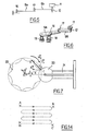
- the force of the disc on the surface to be sanded is controlled ( fig.3 ) by an electric jack (13) coupled to a force sensor (14).
- the elevator (6) only makes it possible to roughly place the sanding tool near or in contact with the surface of the ceiling and the electric cylinder (13) constitutes an actuator which allows a finer adjustment thanks to the sensor of force (14) which gives information on the pressure of the tool on the ceiling.
- Means are provided (not shown) to modify the attitude of the tool to compensate for a possible lack of parallelism between the floor and the ceiling.
- One end of the jack is attached to the arm and the other end of the jack is attached to the drive motor (12) of the tool, which can move in translation in a vertical guide (15).
- the manipulator arm (9) is represented in principle on the figure 5 and in perspective on the figure 6 .
- the arm (9a) is rotatably mounted about a vertical axis (16) and rotated by an actuator (18) constituted by an electric motor.
- the forearm (9b) is articulated on the arm (9a) so as to pivot about a vertical axis (17) under the control of an actuator (19) carried by the arm and which, in the example shown, is deported to better distribute the loads and connected to the forearm by a transmission.
- the actuator is an electric motor.
- the articulation of the forearm on the arm comprises a clutch which serves to follow obstacles when the arm comes into contact with them.
- An angular sensor (not shown) is provided to inform at any time on the configuration of the arm.
- the clutch can be passive or active.
- this clutch is passive and consists of a ball (20) pushed by a spring (21) in a gear (22).
- the spring force must be large enough for the arm to maintain its position under the effect of its own weight.
- the characteristics of this spring will depend on the diameters of the ball and the gear.
- the actuators are controlled by computing means known per se, depending on the desired position and the desired displacement of the sanding disc, and the desired interactions between the robot and its operator.
- the figure 8 schematizes for the example a control architecture, for the control in particular of the elevator, the manipulator arm, as well as the displacement of the assembly.
- the sensors have not been shown in this figure: they are directly connected to the drives (V), to the control boards (C) or to the onboard computer (O).
- the desired commands between the robot and its operator can be very diverse:
- the robot In this lowest level of autonomy, the robot is considered a simple tool handled by a human.
- the man must ensure at all times the control of the robot and the robot must wait for the operator to indicate the instructions.
- the ergonomics of the man / machine interface is a key factor and should tend to improve the operator's ability to immerse themselves in the robot environment and to control it.
- Orders are at a higher level than in the previous case. There is a strong relationship of subordination between the robot and the operator who retains full responsibility for task cycles, which requires concentrated attention.
- the operator instead of defining a sequence of tasks, the operator defines a sequence of behaviors in front of estimates of the robot.
- the operator can activate, simultaneously, several reactive behaviors that can possibly be interactive (obstacle avoidance and trajectory tracking for example).
- the operator remains responsible for the sequence of behaviors and their relevance to the overall mission.
- the robot has the ability to decide to chain an action following the perception of an environment.
- the robot performs tasks autonomously but the operator can intervene at any time.
- the "operator” resource is optimized and used only in cases where it is essential - its use avoids too much sophistication of the robot but requires the latter to take into account human interventions to complete its mission.
- the control of the operator is exercised only on a limited number of mechanisms of the robot.
- the robot's level of autonomy is assessed according to the situation by the robot, who adjusts this level (depending on the occurrence of critical events, or the operator's load or skills), allowing the operator to intervene only at the most appropriate time.
- the mission is based on the ability of the operator and the robot to define their optimum level of cooperation.
- control of the robot can be the responsibility of the man or automatic mechanisms.
- the programming of the robot control takes into account the path of the work that one wants to impose on the tool.
- the figure 14 is an example of a route programmed to sand a surface ABCD.
- the robot is informed about the limits of this surface, for example by knowing the coordinates of the points A, B, C, D, and programs the actuator operations, according to the known procedures of robotics, so that the sanding tool continuously performs a suitable course to cover the surface, for example the course shown in broken lines on the figure 14 , the rolling base being or not stationary and the sanding depth is constant or not during a course.
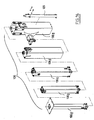
- a sanding disk 111 is rotatably mounted at the end of the axis of a cylinder 113.
- This disc 111 is driven by a motor 112 whose axis is offset relative to the axis of rotation of the sanding disc 111, the drive being done by means of a belt 121.
- a force sensor 114 is disposed at the foot of the cylinder 113.
- the disk 111 is displaced in translation by the cylinder 113 via guides 122 which are able to be moved by sliding along an arm which carries the tool (support arm 123).
- Such a tool makes it possible to remove the material at the level of the ceiling or the treated wall in a controlled manner.
- the depth of material removed is controlled by controlling the force measured by the sensor 114 and controlling the speed of movement along the treated wall.
- the sanding disc 111 can be moved against the wall (ceiling or wall) with a constant effort and a constant speed, which allows to obtain a constant sanding depth.
- the sanding disk 111 is pressed against the wall by the cylinder 113.
- the control of the thrust force is obtained using the force sensor 114, an effort control algorithm - managed with the various controls of the machine at the level of control charts and an onboard computer - to generate the control of the cylinder 113 to ensure that the resisting force of the wall is the same regardless of the disturbances encountered.
- the system is able to deform while turning to 8500 revolutions / minute and acts as a ball joint, the tool being hingedly mounted on the cylinder head by means of an elastic connection 124.
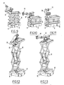
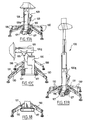
- the scissor lift can be replaced by a telescopic mast 106.
- This telescopic mast consists for example of five tubular elements 106a to 106e, retractable into each other, associated with controlled means 125 of the jack type that control the deployment of the mast.
- the deployable mast 106 is itself pivotally mounted on a base 126.
- Jacks 128 are articulated between the base 126 and one or more clevises 129 projecting from the tubular element 106 which constitutes the element of the mast which is closest to the base 126 and wherein the other tubular elements 106a to 106d fit together.
- the base 126 also includes stabilizing feet 130 may be deployed, with the cylinders 131 to ensure the stabilization of the mast when the assembly is in line with the area on which the tool must intervene.
- the manipulator arm in this case referenced 109, is advantageously slidably mounted along a linear axis 132.
- the translation is provided by a shoe 133 which is mounted on a guide groove which is provided for this purpose on the linear axis 132.
- the entire arm 109 (in this case SCARA type) is itself pivotally mounted on said sliding shoe 133, which allows, for example, the tool 111 to move from a position of the type illustrated in FIG. figure 19 at a 90 ° position of the type illustrated in the figure 20 .
Landscapes
- Engineering & Computer Science (AREA)
- Mechanical Engineering (AREA)
- Robotics (AREA)
- Manipulator (AREA)
Claims (17)
- Vorrichtung zur Behandlung einer Oberfläche, wie zum Beispiel einer Decke oder einer Mauer, wobei die Vorrichtung einen Arm (9) umfasst, an dessen einem Ende ein Werkzeug (11) getragen wird,- wobei der Arm von einem Träger getragen wird, der ein bewegliches Unterteil (4) umfasst.- wobei der Arm (9) ein Gelenkmanipulatorarm ist,- wobei der Träger eine ausfahrbare Hebevorrichtung (6) umfasst, die auf dem beweglichen Unterteil ruht,- wobei das Werkzeug auf einem Zylinder (13) montiert ist, der an einen Beanspruchungssensor (14) gekoppelt ist,- wobei Steuermittel vorgesehen sind, um das Ausfahren der Hebevorrichtung und den Betrieb des Arms zu steuern, um das Werkzeug in Position zu bringen, sowie um den Zylinder zu steuern, um die Anwendungsbeanspruchung des Werkzeugs auf der zu behandelnden Oberfläche zu überprüfen.
- Vorrichtung gemäß Anspruch 1, dadurch gekennzeichnet, dass die Steuermittel außerdem die Bewegungsgeschwindigkeit des Werkzeugs entlang der zu behandelnden Oberfläche überprüfen.
- Vorrichtung gemäß Anspruch 2, dadurch gekennzeichnet, dass das Werkzeug eine Schleifscheibe ist und dass die Steuermittel auf den Zylinder wirken, um die Anwendungsbeanspruchung der Schleifscheibe auf der zu behandelnden Oberfläche konstant zu halten, während die Bewegungsgeschwindigkeit der Schleifscheibe entlang der Oberfläche konstant gehalten wird.
- Vorrichtung gemäß einem der Ansprüche 1 bis 3, dadurch gekennzeichnet, dass der Zylinder ausgelegt ist, die Scheibe parallel zu ihrer Rotationsachse zu bewegen.
- Vorrichtung gemäß Anspruch 1, dadurch gekennzeichnet, dass der Arm ein SCARA entsprechender Arm ist.
- Vorrichtung gemäß Anspruch 1, deren Manipulationsarm (9) einen ersten Arm umfasst, der sich um eine Achse (16) drehen kann und einen Unterarm (9b), der sich auf dem ersten Arm (9a) um eine Achse (17) drehen kann und der an seinem freien Ende das Schleifwerkzeug (11) trägt, wobei diese beiden Drehachsen (16, 17) parallel sind und elektrische Stellglieder (18, 19) vorgesehen sind, um die Rotationen des Arms und Unterarms hervorzurufen.
- Vorrichtung gemäß Anspruch 6 und deren Gelenkverbindung des Unterarms (9b) auf dem Arm (9a) eine Kupplung umfasst.
- Vorrichtung gemäß einem der Ansprüche 1 bis 7 und die Mittel umfasst, um die Orientierung des Werkzeugs zu korrigierten, um einen mögliche Mangel an Parallelität wischen dem Boden und der Decke auszugleichen.
- Vorrichtung gemäß dem Anspruch 1 bis 8, deren Manipulatorarm verschiebbar entlang einer horizontalen Achse auf einer Plattform (7) gelagert ist, die am oberen Teil der Hebevorrichtung befestigt ist.
- Vorrichtung gemäß dem Anspruch 9, bei der die Verschiebung von einem Kugelgewindetriebsystem hervorgerufen wird, das von einem elektrischen Stellglied angetrieben wird.
- Vorrichtung gemäß Anspruch 9 oder 10, deren Manipulatorarm drehbar auf der Plattform um eine horizontale Achse (10) gelagert ist.
- Vorrichtung gemäß einem der Ansprüche 1 bis 11, deren Hebevorrichtung (6) auf dem Unterteil gelagert ist, um um sich selbst um eine vertikale Achse (10) gedreht werden zu können.
- Vorrichtung gemäß einem der Ansprüche 1 bis 12, deren Hebevorrichtung einen Teleskopmasten oder einen Scherenhubtisch (6) umfasst.
- Vorrichtung gemäß einem der Ansprüche 1 bis 12, deren rollendes Unterteil auf Rädern oder auf Raupen (5) montiert ist.
- Vorrichtung gemäß einem der Ansprüche 1 bis 14, deren Werkzeug eine Schrotstrahldüse ist, die das Schrot entlang einer zu den Drehachsen (16, 17) des Arms und des Unterarms parallelen Schleuderachse herausschleudert.
- Vorrichtung gemäß einem der Ansprüche 1 bis 14, deren Werkzeug eine Drehscheibe (11) ist, die von einem Motor (12) angetrieben wird, bei der die Rotationsachse der Schleifscheibe parallel zu den Drehachsen des Arms und des Unterarms ist.
- Verwerdung einer Vorrichtung gemäß einem der Ansprüche 1 bis 16 zum Schleifen einer Decke, einer Mauer oder einer Mauer/Decke-Verbindungsstelle.
Applications Claiming Priority (2)
| Application Number | Priority Date | Filing Date | Title |
|---|---|---|---|
| FR0605070A FR2902038B1 (fr) | 2006-06-07 | 2006-06-07 | Robot de poncage de plafond |
| PCT/EP2007/055630 WO2007141320A1 (fr) | 2006-06-07 | 2007-06-07 | Dispositif pour le traitement d ' une surface |
Publications (2)
| Publication Number | Publication Date |
|---|---|
| EP2035193A1 EP2035193A1 (de) | 2009-03-18 |
| EP2035193B1 true EP2035193B1 (de) | 2010-11-17 |
Family
ID=37685614
Family Applications (1)
| Application Number | Title | Priority Date | Filing Date |
|---|---|---|---|
| EP07765339A Expired - Fee Related EP2035193B1 (de) | 2006-06-07 | 2007-06-07 | Vorrichtung zur behandlung einer oberfläche |
Country Status (4)
| Country | Link |
|---|---|
| EP (1) | EP2035193B1 (de) |
| DE (1) | DE602007010626D1 (de) |
| FR (1) | FR2902038B1 (de) |
| WO (1) | WO2007141320A1 (de) |
Cited By (8)
| Publication number | Priority date | Publication date | Assignee | Title |
|---|---|---|---|---|
| US10414011B2 (en) | 2014-04-15 | 2019-09-17 | Vertical Concrete Polishing Inc. | Method and apparatus for applying a uniform texture to a substantially vertical surface |
| DE102018118750A1 (de) * | 2018-08-02 | 2020-02-06 | Mayumi Geis | Mobiles Steiggerät mit Handhabungsautomat |
| DE102019218485A1 (de) * | 2019-11-28 | 2021-06-02 | Festo Se & Co. Kg | Arbeitseinrichtung |
| EP3932638B1 (de) * | 2020-06-30 | 2023-11-22 | Rocasystems | Verfahren zur herstellung eines bodensystems |
| US11958729B2 (en) | 2017-11-20 | 2024-04-16 | Schwamborn Geraetebau Gmbh | Attachment and handling device with an attachment |
| DE102022212301A1 (de) | 2022-11-18 | 2024-05-23 | Robert Bosch Gesellschaft mit beschränkter Haftung | Autonomes oder manuelles Arbeitsgerät und Verfahren zu einem zumindest teilweise automatischen Bearbeiten eines Objekts |
| DE102022212352A1 (de) | 2022-11-18 | 2024-05-23 | Robert Bosch Gesellschaft mit beschränkter Haftung | Autonomes oder manuelles Arbeitsgerät und Verfahren zu einem zumindest teilweise automatischen Bearbeiten eines Objekts |
| DE102022212340A1 (de) | 2022-11-18 | 2024-05-23 | Robert Bosch Gesellschaft mit beschränkter Haftung | Autonomes oder manuelles Arbeitsgerät und Verfahren zu einem zumindest teilweise automatischen Bearbeiten eines Objekts |
Families Citing this family (31)
| Publication number | Priority date | Publication date | Assignee | Title |
|---|---|---|---|---|
| ATE465941T1 (de) * | 2008-02-12 | 2010-05-15 | Vincenzo Rina | Mobile vorrichtung zum bearbeiten von wasserfahrzeughüllen |
| FR2928571B1 (fr) * | 2008-03-12 | 2010-03-19 | Mbh Dev | Structure roulante support d'au moins un outil de poncage et similaire pour des travaux sur les parois et plafonds |
| DE102009004238A1 (de) * | 2009-01-09 | 2010-07-15 | Uwe Hirschel | Trockenbaudeckenschleifmaschine |
| FR2961121B1 (fr) * | 2010-06-11 | 2013-04-05 | Tournemer | Dispositif d'assistance au portage d'au moins un outil de poncage et/ou de lustrage |
| EP2589327A1 (de) * | 2011-11-04 | 2013-05-08 | Katdangil, Private Stichting | Maschine zur Behandlung von Böden, Wänden oder Decken |
| AT513168B1 (de) * | 2012-08-06 | 2014-08-15 | Braun Maschinenfabrik Gmbh | Vorrichtung zur spanabhebenden Bearbeitung von Flächen |
| EP2960014A3 (de) * | 2014-06-26 | 2016-05-11 | Stefan Lämmle | Schleif- bzw. fräsvorrichtung zur gebäudesanierung |
| NL2013192B1 (en) * | 2014-07-15 | 2016-07-14 | Cobra Carbon Grinding B V | Apparatus and method for grinding carbonaceous materials. |
| DE102015003136A1 (de) * | 2015-03-11 | 2016-09-15 | Kuka Roboter Gmbh | Roboterlagerung |
| CN106041659A (zh) * | 2015-04-15 | 2016-10-26 | 郭蓬莱 | 用于将均匀纹理施加到基本竖直表面的方法和设备 |
| EP3340919B1 (de) * | 2015-08-27 | 2020-09-30 | Focal Healthcare Inc. | System mit beweglicher schnittstelle und stepper |
| FR3050672B1 (fr) | 2016-04-29 | 2018-11-23 | Les Companions | Automate pour le traitement d'une surface |
| FR3050677B1 (fr) | 2016-04-29 | 2020-02-21 | Les Companions | Procede de traitement d'une surface, et automate correspondant |
| WO2018183961A1 (en) | 2017-03-31 | 2018-10-04 | Canvas Construction, Inc. | Automated drywall sanding system and method |
| CN107127650B (zh) * | 2017-06-06 | 2018-01-16 | 史俊生 | 一种吸尘式建筑装饰墙面打磨装置 |
| CN107414624A (zh) * | 2017-08-28 | 2017-12-01 | 东营小宇研磨有限公司 | 自动化地坪机器人混凝土抛光系统 |
| WO2019060920A1 (en) | 2017-09-25 | 2019-03-28 | Canvas Construction, Inc. | AUTOMATED WALL FINISHING SYSTEM AND METHOD |
| DE102018107951B4 (de) * | 2018-04-04 | 2022-06-09 | Lorenz Asbest Gmbh | Bearbeitungsroboter |
| CN108890428A (zh) * | 2018-08-27 | 2018-11-27 | 北京艺轩吉装饰工程有限公司 | 一种装饰工程用升降式无尘墙面打磨机 |
| US11724404B2 (en) | 2019-02-21 | 2023-08-15 | Canvas Construction, Inc. | Surface finish quality evaluation system and method |
| CN110469089B (zh) * | 2019-08-21 | 2021-07-09 | 广东博智林机器人有限公司 | 一种建筑机器人及其升降平移装置 |
| CA3160803A1 (en) * | 2019-11-08 | 2021-05-14 | Vertical Concrete Polishing Inc. | Method and apparatus for applying a uniform texture to an aggregate surface |
| US20230343477A1 (en) * | 2020-01-24 | 2023-10-26 | Westinghouse Electric Company Llc | Universal reactor vessel head inspection platform assembly |
| CN111421410B (zh) * | 2020-04-27 | 2020-12-11 | 福建永东南建设集团有限公司 | 一种自动打磨墙面的设备 |
| CN212287654U (zh) * | 2020-07-02 | 2021-01-05 | 深圳先进技术研究院 | 一种室内装修机器人 |
| CN114161382A (zh) * | 2020-09-10 | 2022-03-11 | 天津大学 | 一种带电作业机器人 |
| CN112428050B (zh) * | 2020-11-16 | 2022-02-25 | 广东博智林机器人有限公司 | 墙面打磨机器人的控制方法及装置 |
| WO2022171417A1 (en) * | 2021-02-12 | 2022-08-18 | Tinymobilerobots Aps | Mobile robot with displaceable spray tool |
| CN113741467B (zh) * | 2021-09-07 | 2023-10-13 | 深圳大方智能科技有限公司 | 一种竖直墙面施工方法及施工机器人 |
| EP4279221A1 (de) * | 2022-05-19 | 2023-11-22 | Hilti Aktiengesellschaft | Bauroboter mit parallelmanipulator |
| KR102552109B1 (ko) * | 2023-01-30 | 2023-07-07 | 주식회사 천일 | 콘크리트 벽면 샌딩장치 |
Family Cites Families (5)
| Publication number | Priority date | Publication date | Assignee | Title |
|---|---|---|---|---|
| AU3583084A (en) * | 1983-12-10 | 1985-06-13 | Aida Engineering Ltd. | Playback grinding robot |
| JPH0985652A (ja) * | 1995-09-20 | 1997-03-31 | Komatsu Ltd | 施工ロボット |
| US6189473B1 (en) * | 1998-02-23 | 2001-02-20 | Remote Tools, Inc. | Contour-following apparatus for cleaning surfaces |
| US7074111B2 (en) * | 2003-09-23 | 2006-07-11 | The Boeing Company | Surface preparation device and method |
| DE102004056344A1 (de) * | 2004-11-22 | 2006-05-24 | Kaefer Isoliertechnik Gmbh & Co Kg | Halter für Maschinen, insbesondere für Schleifmaschinen zum Schleifen im Deckenbereich, sowie Schleifmaschine mit einem solchen Halter |
-
2006
- 2006-06-07 FR FR0605070A patent/FR2902038B1/fr not_active Expired - Fee Related
-
2007
- 2007-06-07 DE DE602007010626T patent/DE602007010626D1/de active Active
- 2007-06-07 WO PCT/EP2007/055630 patent/WO2007141320A1/fr not_active Ceased
- 2007-06-07 EP EP07765339A patent/EP2035193B1/de not_active Expired - Fee Related
Cited By (9)
| Publication number | Priority date | Publication date | Assignee | Title |
|---|---|---|---|---|
| US10414011B2 (en) | 2014-04-15 | 2019-09-17 | Vertical Concrete Polishing Inc. | Method and apparatus for applying a uniform texture to a substantially vertical surface |
| US11958729B2 (en) | 2017-11-20 | 2024-04-16 | Schwamborn Geraetebau Gmbh | Attachment and handling device with an attachment |
| DE102018118750A1 (de) * | 2018-08-02 | 2020-02-06 | Mayumi Geis | Mobiles Steiggerät mit Handhabungsautomat |
| DE102019218485A1 (de) * | 2019-11-28 | 2021-06-02 | Festo Se & Co. Kg | Arbeitseinrichtung |
| DE102019218485B4 (de) | 2019-11-28 | 2022-03-31 | Festo Se & Co. Kg | Arbeitseinrichtung |
| EP3932638B1 (de) * | 2020-06-30 | 2023-11-22 | Rocasystems | Verfahren zur herstellung eines bodensystems |
| DE102022212301A1 (de) | 2022-11-18 | 2024-05-23 | Robert Bosch Gesellschaft mit beschränkter Haftung | Autonomes oder manuelles Arbeitsgerät und Verfahren zu einem zumindest teilweise automatischen Bearbeiten eines Objekts |
| DE102022212352A1 (de) | 2022-11-18 | 2024-05-23 | Robert Bosch Gesellschaft mit beschränkter Haftung | Autonomes oder manuelles Arbeitsgerät und Verfahren zu einem zumindest teilweise automatischen Bearbeiten eines Objekts |
| DE102022212340A1 (de) | 2022-11-18 | 2024-05-23 | Robert Bosch Gesellschaft mit beschränkter Haftung | Autonomes oder manuelles Arbeitsgerät und Verfahren zu einem zumindest teilweise automatischen Bearbeiten eines Objekts |
Also Published As
| Publication number | Publication date |
|---|---|
| DE602007010626D1 (de) | 2010-12-30 |
| FR2902038A1 (fr) | 2007-12-14 |
| EP2035193A1 (de) | 2009-03-18 |
| WO2007141320A1 (fr) | 2007-12-13 |
| FR2902038B1 (fr) | 2009-02-27 |
Similar Documents
| Publication | Publication Date | Title |
|---|---|---|
| EP2035193B1 (de) | Vorrichtung zur behandlung einer oberfläche | |
| EP2394785B1 (de) | Hilfsvorrichtung zum Tragen von mindestens einem Schleif- und/oder Polierwerkzeug | |
| KR101622331B1 (ko) | 스위핑 차량 | |
| CN102282321B (zh) | 用于遥控工作机的控制系统 | |
| JP6635331B2 (ja) | 複腕移動ロボット | |
| EP0608187B1 (de) | Verfahren zur hybriden Positions/Kraft-Steuerung für einen Robotermanipulator | |
| JP2003326478A (ja) | オフセット回転関節を有するロボット | |
| EP2103381A1 (de) | Rollstruktur als Halterung für mindestens ein Schleifinstrument oder Ähnliches für Arbeiten an Wänden und Decken | |
| US10144619B2 (en) | Attachment with vacuum and grab arms | |
| JP2016055663A (ja) | クローラ式無人車とその動作方法 | |
| FR2960467A1 (fr) | Equipement de robotique collaborative | |
| US20230304252A1 (en) | Compact utility loader with synchronized lift and extension of working tool attachment | |
| EP0393004B1 (de) | Hebevorrichtung | |
| WO2006111827A1 (fr) | Dispositif d'aide a la construction de murs et/ou au traitement de surfaces | |
| EP3310968B1 (de) | Reinigungsvorrichtung, insbesondere eines grabens, und anordnung mit solch einer reinigungsvorrichtung | |
| JP6771289B2 (ja) | ボルト回転装置 | |
| US10725362B2 (en) | Light weight two or three axis remote camera head | |
| JP2010000945A (ja) | クローラ走行装置 | |
| EP0402216B1 (de) | Vorrichtung zur krummliniegen Bewegung eines Gegenstandes in Berührung mit einer Fläche, insbesondere einer konvexen Fläche | |
| JP6912285B2 (ja) | 水中移動装置および方法 | |
| US20170043445A1 (en) | Grinding/milling machine for levelling of horizontal surfaces | |
| EP0143134A1 (de) | Gewichtsausgleichsvorrichtung für Roboterarm | |
| WO2018193821A1 (ja) | 昇降装置 | |
| KR101495605B1 (ko) | 무인 제설기 | |
| EP1800796A1 (de) | Tragkonstruktion für eine Stabpoliermaschine |
Legal Events
| Date | Code | Title | Description |
|---|---|---|---|
| PUAI | Public reference made under article 153(3) epc to a published international application that has entered the european phase |
Free format text: ORIGINAL CODE: 0009012 |
|
| 17P | Request for examination filed |
Effective date: 20081217 |
|
| AK | Designated contracting states |
Kind code of ref document: A1 Designated state(s): AT BE BG CH CY CZ DE DK EE ES FI FR GB GR HU IE IS IT LI LT LU LV MC MT NL PL PT RO SE SI SK TR |
|
| AX | Request for extension of the european patent |
Extension state: AL BA HR MK RS |
|
| RBV | Designated contracting states (corrected) |
Designated state(s): DE FR GB |
|
| RIN1 | Information on inventor provided before grant (corrected) |
Inventor name: DE BROISSIA, MICHEL Inventor name: LEGRAND, FLAVIEN Inventor name: HASSELVANDER, RODOLPHE Inventor name: RICHARD, PHILIPPE Inventor name: PICQUAND, JEAN-PHILIPPE |
|
| 17Q | First examination report despatched |
Effective date: 20090812 |
|
| GRAP | Despatch of communication of intention to grant a patent |
Free format text: ORIGINAL CODE: EPIDOSNIGR1 |
|
| DAX | Request for extension of the european patent (deleted) | ||
| GRAS | Grant fee paid |
Free format text: ORIGINAL CODE: EPIDOSNIGR3 |
|
| GRAA | (expected) grant |
Free format text: ORIGINAL CODE: 0009210 |
|
| AK | Designated contracting states |
Kind code of ref document: B1 Designated state(s): DE FR GB |
|
| REG | Reference to a national code |
Ref country code: GB Ref legal event code: FG4D Free format text: NOT ENGLISH |
|
| REF | Corresponds to: |
Ref document number: 602007010626 Country of ref document: DE Date of ref document: 20101230 Kind code of ref document: P |
|
| PGFP | Annual fee paid to national office [announced via postgrant information from national office to epo] |
Ref country code: FR Payment date: 20110621 Year of fee payment: 5 |
|
| PGFP | Annual fee paid to national office [announced via postgrant information from national office to epo] |
Ref country code: GB Payment date: 20110523 Year of fee payment: 5 |
|
| PLBE | No opposition filed within time limit |
Free format text: ORIGINAL CODE: 0009261 |
|
| STAA | Information on the status of an ep patent application or granted ep patent |
Free format text: STATUS: NO OPPOSITION FILED WITHIN TIME LIMIT |
|
| 26N | No opposition filed |
Effective date: 20110818 |
|
| PGFP | Annual fee paid to national office [announced via postgrant information from national office to epo] |
Ref country code: DE Payment date: 20110728 Year of fee payment: 5 |
|
| REG | Reference to a national code |
Ref country code: DE Ref legal event code: R097 Ref document number: 602007010626 Country of ref document: DE Effective date: 20110818 |
|
| GBPC | Gb: european patent ceased through non-payment of renewal fee |
Effective date: 20120607 |
|
| REG | Reference to a national code |
Ref country code: FR Ref legal event code: ST Effective date: 20130228 |
|
| REG | Reference to a national code |
Ref country code: DE Ref legal event code: R119 Ref document number: 602007010626 Country of ref document: DE Effective date: 20130101 |
|
| PG25 | Lapsed in a contracting state [announced via postgrant information from national office to epo] |
Ref country code: GB Free format text: LAPSE BECAUSE OF NON-PAYMENT OF DUE FEES Effective date: 20120607 Ref country code: DE Free format text: LAPSE BECAUSE OF NON-PAYMENT OF DUE FEES Effective date: 20130101 Ref country code: FR Free format text: LAPSE BECAUSE OF NON-PAYMENT OF DUE FEES Effective date: 20120702 |