EP2035732B1 - Dichtung und dichtungsanordnung - Google Patents
Dichtung und dichtungsanordnung Download PDFInfo
- Publication number
- EP2035732B1 EP2035732B1 EP07764378A EP07764378A EP2035732B1 EP 2035732 B1 EP2035732 B1 EP 2035732B1 EP 07764378 A EP07764378 A EP 07764378A EP 07764378 A EP07764378 A EP 07764378A EP 2035732 B1 EP2035732 B1 EP 2035732B1
- Authority
- EP
- European Patent Office
- Prior art keywords
- sealing
- seal
- groove
- recess
- sealing ring
- Prior art date
- Legal status (The legal status is an assumption and is not a legal conclusion. Google has not performed a legal analysis and makes no representation as to the accuracy of the status listed.)
- Not-in-force
Links
Images
Classifications
-
- F—MECHANICAL ENGINEERING; LIGHTING; HEATING; WEAPONS; BLASTING
- F16—ENGINEERING ELEMENTS AND UNITS; GENERAL MEASURES FOR PRODUCING AND MAINTAINING EFFECTIVE FUNCTIONING OF MACHINES OR INSTALLATIONS; THERMAL INSULATION IN GENERAL
- F16J—PISTONS; CYLINDERS; SEALINGS
- F16J15/00—Sealings
- F16J15/16—Sealings between relatively-moving surfaces
- F16J15/164—Sealings between relatively-moving surfaces the sealing action depending on movements; pressure difference, temperature or presence of leaking fluid
-
- F—MECHANICAL ENGINEERING; LIGHTING; HEATING; WEAPONS; BLASTING
- F16—ENGINEERING ELEMENTS AND UNITS; GENERAL MEASURES FOR PRODUCING AND MAINTAINING EFFECTIVE FUNCTIONING OF MACHINES OR INSTALLATIONS; THERMAL INSULATION IN GENERAL
- F16J—PISTONS; CYLINDERS; SEALINGS
- F16J15/00—Sealings
- F16J15/16—Sealings between relatively-moving surfaces
- F16J15/32—Sealings between relatively-moving surfaces with elastic sealings, e.g. O-rings
- F16J15/3204—Sealings between relatively-moving surfaces with elastic sealings, e.g. O-rings with at least one lip
- F16J15/322—Sealings between relatively-moving surfaces with elastic sealings, e.g. O-rings with at least one lip supported in a direction perpendicular to the surfaces
-
- F—MECHANICAL ENGINEERING; LIGHTING; HEATING; WEAPONS; BLASTING
- F16—ENGINEERING ELEMENTS AND UNITS; GENERAL MEASURES FOR PRODUCING AND MAINTAINING EFFECTIVE FUNCTIONING OF MACHINES OR INSTALLATIONS; THERMAL INSULATION IN GENERAL
- F16J—PISTONS; CYLINDERS; SEALINGS
- F16J15/00—Sealings
- F16J15/16—Sealings between relatively-moving surfaces
- F16J15/32—Sealings between relatively-moving surfaces with elastic sealings, e.g. O-rings
- F16J15/3204—Sealings between relatively-moving surfaces with elastic sealings, e.g. O-rings with at least one lip
- F16J15/3232—Sealings between relatively-moving surfaces with elastic sealings, e.g. O-rings with at least one lip having two or more lips
- F16J15/3236—Sealings between relatively-moving surfaces with elastic sealings, e.g. O-rings with at least one lip having two or more lips with at least one lip for each surface, e.g. U-cup packings
Definitions
- the invention relates to a seal for sealing a sealing surface between two relatively movable machine parts, wherein a sealing body of the seal has a nutgroundmon in a groove of the machine parts to be arranged holding part, a sealing surface side to be arranged in the groove sealing part and a flexible connecting part between the sealing part and the holding part wherein the seal comprises a recess formed between the holding part and the connecting part and a further recess formed between the connecting part and the sealing part, and wherein the seal is formed as a sealing ring and a sealing arrangement, wherein the seal in a groove of one of two relatively movable Machine parts is arranged.
- Such seals have a cross-sectionally S-shaped or Z-shaped basic shape, wherein the indentations are formed by this basic shape.
- the gaskets are usually made in one piece from a rubber elastic material, e.g. Polyurethane or rubber produced and designed as a radially symmetrical sealing ring.
- the seals are used as rod or piston seals for sealing in pneumatic applications, e.g. Pneumatic cylinders or valves, and / or as rotary seals, e.g. in high pressure applications.
- Such a seal is usually inserted between two mutually axially and / or rotationally moving machine parts in a groove in a surface of one of the machine parts, said surface being arranged opposite one of the sealing surfaces formed by a surface of the second machine part. Between the surfaces mentioned so is the sealed sealing gap. In the case of a sealing ring, the two surfaces are thus aligned concentrically with each other.
- the groove is arranged in the inner machine part, in a rod seal, the groove is arranged in the outer machine part.
- the resilient connecting part acts like a spring between the usually at least one sealing lip having sealing part and the holding part.
- the holding part is dimensioned such that it allows a positionally fixed as possible seat of the seal on the groove base.
- the seal When using such a seal, for example in a pneumatic cylinder, the seal is mutually subjected to a pressurized medium, ie a fluid, eg oil and / or air, which is located in a pressure chamber.
- a pressurized medium ie a fluid, eg oil and / or air
- the seal With preload inserted in the groove.
- the seal is compressed in such a way that the spring action of the connecting part presses the sealing surface side surface of the sealing part against the sealing surface.
- the sealing ring In the case of a sealing ring, the sealing ring is compressed radially.
- the indentations of the seal serve for pressure activation under load through the medium. Characterized in that the pressurized medium flows into the recesses, the sealing part is pressed in addition to the spring action of the connecting part to the sealing surface.
- such a seal with its groove flanks of the groove facing surfaces (side surfaces) spaced from the groove flanks inserted in the groove. The medium can therefore
- the EP 0 906 528 B1 discloses a generic seal which is designed as a sealing ring, with provisions are already made against overblowing.
- the sealing ring has radially extending pressure equalization channels, which allow the media to flow in on both sides of the sealing ring into the indentations of the sealing ring.
- the radial pressure equalization channels can not prevent the tilting of the sealing part.
- a generic seal is also from the EP 0 152 938 A2 known.
- the previously known seal has a holding part, a sealing part and a connecting part, wherein between the holding part and the connecting part and between the sealing part and the connecting part in each case a recess is provided.
- the seal further comprises projecting surface portions, which are arranged on the end face of the sealing part. The protruding surface portions can not prevent the tilting of the sealing part.
- the BE 632 658 A discloses a seal, with a sealing part a holding part and a connecting part, wherein between the sealing part and the holding part a recess is formed. In the indentation, a spacer element is provided which has pressure equalization paths. The holding part and the sealing part are compared to the connecting part elastically deformable to a small extent. The seal has a low spring action.
- the invention has for its object to provide a seal and a seal assembly, which avoid the disadvantages of the prior art and in particular prevent the occurrence of malfunction of a blow-by good sealing function in any installation situation.
- a seal according to the invention for sealing a sealing surface between two relatively movable machine parts has a sealing body with a groove in one of the machine parts nutground document to be arranged holding part, a sealing surface side to be arranged in the groove sealing part (with at least one sealing lip) and a flexible connecting part between the sealing part and the Holding part on. At least one sealing lip can be formed on the sealing part.
- At the seal, or its sealing body is formed between the holding part and the connecting part indentation and formed between the connecting part and the sealing part further indentation available. The indentations protrude into the dimensions of the seal body.
- the gasket may be shaped as a gasket of S-shaped or Z-shaped basic shape.
- the seal on spacer elements wherein the spacer elements in at least one of the recesses, at least the recess formed between the sealing part and the connecting part, are provided.
- the spacer elements thus protrude radially beyond the indentations forming surfaces of the seal body.
- the spacer elements Even if the seal is compressed in the installed state, the associated indentation remains at least partially open.
- the integrally formed on the sealing part spacer elements are then, with correspondingly strong compression, with its free end on the opposite part surface of the indentation.
- a cavity is formed by the near-valley indentation, in which, preferably via one or more connecting channels, a medium for pressure activation of the sealing ring can flow.
- the spacer elements result in a support of the seal, whereby a tilting of the seal can be prevented, so that the occurrence of a blow-by is counteracted. This allows a trouble-free use of the seal according to the invention as a seal for reciprocating movements or rotational movements.
- the seal according to the invention has at least one pressure equalization channel, wherein the pressure equalization channels form pressure equalization paths between the indentation between the connecting part and the sealing part and at least one surface of the seal to be arranged on a groove flank of the groove.
- the pressure equalization channels are thus arranged so that at least in the sealing gap-side recess, the medium can flow from a pressure chamber.
- Such a pressure equalization channel allows unimpeded inflow of the medium from the pressure chamber in the recess for pressure activation of the sealing surface side surface of the sealing part of the seal even in the compressed (installation) state of the seal.
- the spacer elements in the outer region of the indentations, i. are arranged close to the side surfaces of the seal, so blocking of the inflow of the medium can be prevented in a lying in the inner region of the recess clearance.
- the seal is designed as a sealing ring.
- the sealing part may be arranged on the sealing ring radially on the outside, so that the sealing ring can be inserted in a customary manner into a groove of the piston.
- the sealing part is preferably arranged radially on the inside of the sealing ring.
- the pressure equalization channels are structurally simple formed by interruptions of the spacer elements.
- the spacer elements When the spacer elements are used as being in the longitudinal direction of the indentations, i. If a sealing ring has radially protruding, circular-arc-shaped ribs, the spacer elements may be formed in such a way that in the interior region of the indentations coherent free spaces, i. in the case of a sealing ring, radially surrounding free spaces remain, into which the medium can preferably flow in via connecting channels.
- the pressure activation thus acts evenly over the entire length of the seal, or on its entire circumference.
- the spacer elements may also be provided by punctiform, e.g. Conical elevations may be formed.
- the seal has at least one pressure equalization channel between the indentation between the connection part and the holding part and at least one surface of the seal to be arranged on a groove flank of the groove, pressure activation of the holding part in the groove base can also be ensured with the above-described geometric relationships.
- a seal according to the invention is arranged in a groove of one of two relatively movable machine parts.
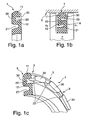
- FIGS. 1 show a sealing ring according to the invention in various, partially perspective, representations.
- a seal 1 according to the invention is in each case inserted to seal a sealing surface 5 between two relatively movable machine parts 6, 7 in a groove 8 in one of the machine parts 7.
- the seal 1 is preferably made in one piece from a rubber-elastic material.
- the sealing body has a nutground document arranged holding part 10, a sealing surface side disposed in the groove 8 sealing part 11 and a resilient connecting part 12 between the sealing part 11 and the holding part 10.
- a recess 20 between the holding part 11 and the connecting part 12 (close to the recess) is formed.
- a further indentation 21 is formed between the connecting part 12 and the sealing part 10 (groove-like indentation).
- spacer elements 25 are formed, which protrude into the recesses 20,21.
- the spacer elements 25 are formed as in the longitudinal direction of the indentations 20,21, that is, in a sealing ring radially extending ribs.
- the sealing surface 5 facing surface of the sealing member 11 a curvature. The degree formed by this curvature forms a sealing lip.
- the pressure equalization channels 3 form pressure equalization paths between the recesses 20,21 and each one arranged on a groove flank of the groove 8 surface of the seal 1, that is, a side surface of the seal 1 from.
- FIGS. 1 show a sealing ring 1 according to the invention with rib-like elevations for forming axial and radial pressure equalization channels 3 in different perspectives.
- the FIG. 1a shows one half of a sealing ring 1 according to the invention prior to its installation in cross-section
- the FIG. 1b shows a half of a seal assembly according to the invention with the built between two mutually movable machine parts 6,7 in a groove 8 sealing ring 1 in cross-section
- Figure 1c shows a part of a three-dimensional representation of the cut-open sealing ring 1.
- the sectional plane of the cross-sectional views is guided in each case through one of the pressure compensation channels 3.
- On the sealing ring 1 radially circumferential groove edge spacers 30 are integrally formed.
- the groove flank spacers 30 present on the near-surface indentation 20 project as an interrupted rib-like elevation into the indentation 20 close to the surface, whereby the groove flank spacers 30 also serve as spacer elements 25.
- the groove flank spacing elements 30 and the spacer elements 25 thus merge into one another and are arranged in the region of the surface of the sealing part 11 on the indentation 20, ie the indentation 20 close to the gasket, or formed on the sealing part 11.
- the pressure compensation channels 3 are formed by interruptions of these groove edge spacers 30.
- the pressure equalization channels 3 extend on the sealing ring 1 in the region of the spacer elements 25 serving as spacer elements 25 in the near-valley recess 20 in the axial direction and extend on the side surface of the sealing ring 1 in the radial direction, ie in the direction of the groove bottom to the sealing surface 5. So there in the radial direction extending pressure equalization channels 3 combined with extending in the axial direction pressure equalization channels 3.
- FIG. 1b It can be seen that the sealing ring 1 in the installed state in the radial direction is pressed together so far that the formed on the sealing member 11 spacer elements 25 abut with its free end on the part formed by the connecting part 12 of the near-surface recess 20. Despite this compressed state, a cavity is formed by the near-valley indentation 20, in which a medium for pressure activation of the sealing ring 1 can flow.
- a seal 1 for sealing a sealing surface 5 between two relatively movable machine parts 6,7, wherein a sealing body of the seal 1 in a groove 8 of the machine parts 7 nutground document to be arranged holding part 10, a sealing surface side in the groove 8 to be arranged sealing member 11 and a resilient connecting part 12 between the sealing part 11 and the holding part 10, and wherein the seal 1 has a formed between the holding part 10 and the connecting part 12 indentation 21 and formed between the connecting part 12 and the sealing part 11 further indentation 20.
- the seal 1 has spacer elements 25, wherein the spacer elements 25 protrude into at least one of the recesses 20, 21, at least the indentation 20 formed between the sealing part 11 and the connecting part 12.
- the invention is not limited to the embodiments given above. Rather, a number of variants are conceivable, which make use of the features of the invention even with fundamentally different type of execution.
Landscapes
- Engineering & Computer Science (AREA)
- General Engineering & Computer Science (AREA)
- Mechanical Engineering (AREA)
- Sealing Devices (AREA)
- Gasket Seals (AREA)
Abstract
Description
- Die Erfindung betrifft eine Dichtung zur Abdichtung einer Dichtfläche zwischen zwei relativ zueinander beweglichen Maschinenteilen, wobei ein Dichtkörper der Dichtung ein in einer Nut eines der Maschinenteile nutgrundseitig anzuordnendes Halteteil, einen dichtflächenseitig in der Nut anzuordnenden Dichtteil und ein nachgiebiges Verbindungsteil zwischen dem Dichtteil und dem Halteteil aufweist, wobei die Dichtung eine zwischen dem Halteteil und dem Verbindungsteil ausgebildete Einbuchtung und eine zwischen dem Verbindungsteil und dem Dichtteil ausgebildete weitere Einbuchtung aufweist, und wobei die Dichtung als Dichtring ausgebildet ist sowie eine Dichtungsanordnung, wobei die Dichtung in einer Nut eines von zwei relativ zueinander beweglichen Maschinenteilen angeordnet ist.
- Derartige Dichtungen weisen eine im Querschnitt S- oder Z-förmige Grundform auf, wobei die Einbuchtungen von dieser Grundform gebildet werden. Die Dichtungen sind meist einstückig aus einem gummielastischen Material, z.B. Polyurethan oder Gummi hergestellt und als radialsymmetrischer Dichtring ausgeführt. In dieser Ausführung sind die Dichtungen als Stangen- oder Kolbendichtungen für die Abdichtung in Pneumatikanwendungen, z.B. Pneumatikzylindern oder Ventilen, und/oder als Rotationsdichtungen, z.B. in Hochdruckanwendungen, einsetzbar.
- Eine derartige Dichtung wird üblicherweise zwischen zwei zueinander axial und/oder drehend bewegten Maschinenteilen in einer Nut in einer Oberfläche eines der Maschinenteile eingesetzt, wobei diese Oberfläche einer der von einer Oberfläche des zweiten Maschinenteils ausgebildeten Dichtfläche gegenüberliegend angeordnet ist. Zwischen den genannten Oberflächen befindet sich also der abzudichtende Dichtspalt. Im Falle eines Dichtrings sind die beiden Oberflächen also konzentrisch zueinander ausgerichtet. Üblicherweise ist bei einer Kolbendichtung die Nut im inneren Maschinenteil angeordnet, bei einer Stangendichtung ist die Nut im äußeren Maschinenteil angeordnet. Das nachgiebige Verbindungsteil wirkt wie eine Feder zwischen dem üblicherweise mindestens eine Dichtlippe aufweisenden Dichtteil und dem Halteteil. Das Halteteil ist derart dimensioniert, dass es einen möglichst lagefixierten Sitz der Dichtung am Nutgrund ermöglicht.
- Beim Einsatz einer derartigen Dichtung z.B. in einem Pneumatikzylinder wird die Dichtung wechselseitig mit einem unter Druck stehenden Medium, d.h. einem Fluid, z.B. Öl und/oder Luft, beaufschlagt, das sich in einem Druckraum befindet. Um die gewünschte Dichtwirkung zu erzielen, wird die Dichtung mit Vorspannung in die Nut eingelegt. Dazu wird die Dichtung derart zusammengepresst, dass die Federwirkung des Verbindungsteils die dichtflächenseitige Oberfläche des Dichtteils an die Dichtfläche presst. Im Falle eines Dichtrings wird der Dichtring dazu radial zusammengepresst. Die Einbuchtungen der Dichtung dienen zu einer Druckaktivierung bei Belastung durch das Medium. Dadurch, dass das unter Druck stehende Medium in die Einbuchtungen einfließt, wird der Dichtteil zusätzlich zur Federwirkung des Verbindungsteils an die Dichtfläche gepresst. Dazu ist eine derartige Dichtung mit ihren den Nutflanken der Nut zugewandten Oberflächen (Seitenoberflächen) beabstandet zu den Nutflanken in der Nut eingelegt. Das Medium kann daher zwischen den Nutflanken und den Seitenoberflächen in die Einbuchtungen einfließen.
- Die dem Dichtteil benachbarte Einbuchtung kann jedoch zu Fehlfunktionen beim Betrieb, z.B. eines Pneumatikzylinders führen. Durch die bei der Bewegung der Maschinenteile, welche mittels der Dichtung gegeneinander abgedichtet werden, auftretenden Kräfte auf die Dichtung und/oder durch die dabei auftretende wechselseitige Druckbelastung durch das Medium kann es zu einem Verkippen des Dichtteils (Abkippen) in der Nut kommen. Ist dies der Fall kann, ausgehend von einer Druckbeaufschlagung p1 an einer der Seitenoberflächen, ein Druckaufbau p2 an der Gegenseite, also an der zweiten Seitenoberfläche, zu einem Abheben der Dichtung von der Dichtfläche führen. Wenn dieses Abheben aufgetreten ist, ist keinerlei Dichtfunktion mehr gegeben. Diese Fehlfunktion wird als Überblasen der Dichtung (Blow-By) bezeichnet. Erst nach Wegnahme des Drucks an beiden Seitenoberflächen wird die Dichtfunktion der Dichtung wieder hergestellt.
- Die
EP 0 906 528 B1 offenbart eine gattungsgemäße Dichtung die als Dichtring ausgebildet ist, wobei bereits Vorkehrungen gegen ein Überblasen getroffen sind. Der Dichtring weist dazu radial verlaufende Druckausgleichskanäle auf, die ein Einfließen der Medien beiderseits des Dichtrings in die Einbuchtungen des Dichtringes ermöglichen. Die radialen Druckausgleichskanäle können das Abkippen des Dichtteils jedoch nicht verhindern. - Fallweise werden deshalb derartige Dichtungen auf Block gedrückt eingebaut, d.h. die Dichtungen werden derart stark, im Falle von Dichtringen radial-, zusammengedrückt, dass die Einbuchtungen vom Zwischenteil ausgefüllt werden, d.h. im eingebauten Zustand praktisch nicht mehr ihre Funktion, also das Ermöglichen einer Druckaktivierung, erfüllen können. Zwar wird so ein Abkippen des Profils der Dichtung im dynamischen Dichtbereich verhindert, jedoch ist das Funktionsverhalten der Dichtung dadurch stark beeinträchtigt und die Reibung erhöht.
- Eine gattungsgemäße Dichtung ist ebenfalls aus der
EP 0 152 938 A2 bekannt. Die vorbekannte Dichtung weist ein Halteteil, ein Dichtteil und ein Verbindungsteil auf, wobei zwischen Halteteil und Verbindungsteil und zwischen Dichtteil und Verbindungsteil jeweils eine Einbuchtung vorgesehen ist. Die Dichtung weist weiter vorspringende Flächenanteile auf, die an der Stirnseite des Dichtteils angeordnet sind. Die vorspringenden Flächenanteile können das Abkippen des Dichtteils nicht verhindern. - Die
BE 632 658 A - Der Erfindung liegt die Aufgabe zugrunde, eine Dichtung und eine Dichtungsanordnung bereitzustellen, welche die Nachteile des Standes der Technik vermeiden und insbesondere das Auftreten der Fehlfunktion eines Blow-By bei guter Dichtfunktion in beliebiger Einbausituation verhindern.
- Diese Aufgabe wird durch die Gegenstände der unabhängigen Patentansprüche gelöst. Die abhängigen Ansprüche stellen bevorzugte Ausführungsformen der Erfindung dar.
- Eine erfindungsgemäße Dichtung zur Abdichtung einer Dichtfläche zwischen zwei relativ zueinander beweglichen Maschinenteilen weist einen Dichtungskörper mit einem in einer Nut eines der Maschinenteile nutgrundseitig anzuordnenden Halteteil, einem dichtflächenseitig in der Nut anzuordnenden Dichtteil (mit mindestens einer Dichtlippe) und einem nachgiebigen Verbindungsteil zwischen dem Dichtteil und dem Halteteil auf. Am Dichtteil kann mindestens eine Dichtlippe angeformt sein. An der Dichtung, bzw. deren Dichtungskörper, ist eine zwischen dem Halteteil und dem Verbindungsteil ausgebildete Einbuchtung und eine zwischen dem Verbindungsteil und dem Dichtteil ausgebildete weitere Einbuchtung vorhanden. Die Einbuchtungen ragen in die Abmessungen des Dichtungskörpers ein. Derart kann die Dichtung als eine Dichtung mit S- oder Z-förmiger Grundform ausgeprägt sein.
- Erfindungsgemäß weist die Dichtung Abstandshalteelemente auf, wobei die Abstandshalteelemente in mindestens einer der Einbuchtungen, mindestens der zwischen dem Dichtteil und dem Verbindungsteil ausgebildeten Einbuchtung, vorgesehen sind. Die Abstandshalteelemente ragen also über die die Einbuchtungen ausbildenden Oberflächen des Dichtungskörpers radial hinaus.
- Durch die Abstandshalteelemente bleibt, auch wenn die Dichtung im eingebauten Zustand zusammengepresst ist, die zugehörige Einbuchtung zumindest teilweise offen. Die am Dichtungsteil angeformten Abstandshalteelemente liegen dann, bei entsprechend starker Stauchung, mit ihrem freien Ende an der gegenüberliegenden Teiloberfläche der Einbuchtung an. Trotz dieses zusammengepressten Zustands wird also von der dichtflächennahen Einbuchtung ein Hohlraum ausgebildet, in den,bevorzugt über einen oder mehrere Verbindungskanäle, ein Medium zur Druckaktivierung des Dichtrings einströmen kann. Auf diese Weise ist eine Druckaktivierung der Dichtung auch bei starker Stauchung gewährleistet. Zusätzlich ergibt sich durch die Abstandshalteelemente eine Abstützung der Dichtung, wodurch ein Abkippen der Dichtung verhindert werden kann, so dass dem Auftreten eines Blow-By entgegen gewirkt wird. Dies ermöglicht einen störungsfreien Einsatz der erfindungsgemäßen Dichtung als Dichtung für hin- und hergehende Bewegungen oder Rotationsbewegungen.
- Die erfindungsgemäße Dichtung weist mindestens einen Druckausgleichskanal auf, wobei die Druckausgleichskanäle Druckausgleichswege zwischen der Einbuchtung zwischen dem Verbindungsteil und dem Dichtteil und mindestens einer an einer Nutflanke der Nut anzuordnenden Oberfläche der Dichtung ausbilden. Die Druckausgleichskanäle sind also so angeordnet, dass mindestens in die dichtspaltseitige Einbuchtung das Medium aus einem Druckraum einströmen kann. Ein derartiger Druckausgleichskanal ermöglicht auch im zusammengepressten (Einbau-)Zustand der Dichtung das ungehinderte Einströmen des Mediums aus dem Druckraum in die Einbuchtung zur Druckaktivierung der dichtflächenseitigen Oberfläche des Dichtteils der Dichtung. Insbesondere wenn die Abstandshalteelemente im Außenbereich der Einbuchtungen, d.h. nahe an den Seitenoberflächen der Dichtung angeordnet sind, kann so ein Blockieren des Einströmens des Mediums in einen im Innenbereich der Einbuchtung liegenden Freiraum verhindert werden.
- Zum Einsatz der erfindungsgemäßen Dichtung zwischen radialsymmetrischen Maschinenteilen, z.B. einer Kolben-Zylinderanordnung oder einer rotierenden Welle, ist die Dichtung als Dichtring ausgebildet. Im Falle eines in einem Zylinder bewegten Kolbens kann der Dichtteil am Dichtring radial außen angeordnet sein, so dass der Dichtring in üblicher Weise in eine Nut des Kolbens einlegbar ist. Im Falle des Einsatzes als Stangendichtung ist der Dichtteil am Dichtring bevorzugt radial innen angeordnet.
- Die Druckausgleichskanäle sind konstruktiv einfach durch Unterbrechungen der Abstandshalteelemente ausgebildet.
- Wenn die Abstandshalteelemente als in Längsrichtung der Einbuchtungen, d.h. bei einem Dichtring radial ausragende, kreisbogenförmig verlaufende Rippen ausgebildet sind, können die Abstandshalreelemente so ausgeformt sein, dass im Innenbereich der Einbuchtungen zusammenhängende Freiräume, d.h. bei einem Dichtring radial umlaufende Freiräume, verbleiben, in die das Medium bevorzugt über Verbindungskanäle einströmen kann. Die Druckaktivierung wirkt dadurch gleichmäßig auf der gesamten Länge der Dichtung, bzw. auf deren gesamten Umfang. Alternativ können die Abstandshalteelemente auch durch punktuelle, z.B. Kegelförmige Erhebungen ausgebildet sein.
- Wenn die Dichtung mindestens einen Druckausgleichskanal zwischen der Einbuchtung zwischen dem Verbindungsteil und dem Halteteil und mindestens einer an einer Nutflanke der Nut anzuordnenden Oberfläche der Dichtung aufweist, kann auch eine Druckaktivierung des Halteteils im Nutgrund bei den vorbeschriebenen Geometrieverhältnissen gesichert werden.
- In einer erfindungsgemäßen Dichtungsanordnung ist eine erfindungsgemäße Dichtung in einer Nut eines von zwei relativ zueinander beweglichen Maschinenteilen angeordnet.
- Die Erfindung wird nachfolgend anhand von Ausführungsbeispielen unter Bezugnahme auf die Zeichnungen näher erläutert.
- Die
Figuren 1 zeigen einen erfindungsgemäßen Dichtring in verschiedenen, teilweise perspektivischen, Darstellungen. - Die Figuren der Zeichnungen zeigen den erfindungsgemäßen Gegenstand stark schematisiert und sind nicht maßstäblich zu verstehen. Die einzelnen Bestandteile des erfindungsgemäßen Gegenstandes sind so dargestellt, dass ihr Aufbau gut gezeigt werden kann.
- Eine erfindungsgemäße Dichtung 1 ist jeweils zur Abdichtung einer Dichtfläche 5 zwischen zwei relativ zueinander beweglichen Maschinenteilen 6,7 in eine Nut 8 in einem der Maschinenteile 7 eingelegt. Die Dichtung 1 ist bevorzugt einstückig aus einem gummielastischen Material hergestellt.
- Zu beiden Seiten des zweiten Maschinenteils 7, z.B. einem Kolben in einer Pneumatikanwendung, steht jeweils ein unter einem Druck p1, bzw. p2, stehendes Medium an. Der Dichtungskörper weist einen nutgrundseitig angeordneten Halteteil 10, einen dichtflächenseitigen in der Nut 8 angeordneten Dichtteil 11 und einen nachgiebigen Verbindungsteil 12 zwischen dem Dichtteil 11 und dem Halteteil 10 auf. Im Dichtkörper der Dichtung 1 ist eine Einbuchtung 20 zwischen dem Halteteil 11 und dem Verbindungsteil 12 (dichtflächennahe Einbuchtung) ausgebildet. Eine weitere Einbuchtung 21 ist zwischen dem Verbindungsteil 12 und dem Dichtteil 10 (nutgrundnahe Einbuchtung) ausgebildet. Am Dichtkörper der Dichtung 1 sind Abstandshalteelemente 25 ausgebildet, die in die Einbuchtungen 20,21 einragen. Die Abstandshalteelemente 25 sind als in Längsrichtung der Einbuchtungen 20,21, d.h. bei einem Dichtring radial, verlaufende Rippen ausgebildet. In den Darstellungen der Figuren weist die der Dichtfläche 5 zugewandte Oberfläche des Dichtteils 11 eine Wölbung auf. Der durch diese Wölbung gebildete Grad bildet eine Dichtlippe aus.
- Die Druckausgleichskanäle 3 bilden Druckausgleichswege zwischen den Einbuchtungen 20,21 und jeweils einer an einer Nutflanke der Nut 8 angeordneten Oberfläche der Dichtung 1, also einer Seitenoberfläche der Dichtung 1, aus.
- Dadurch, dass in beiden Einbuchtungen 20,21 Druckausgleichskanäle 3 enden wird bei den dargestellten Dichtungen 1 durch eine Druckaktivierung sowohl die Dichtwirkung verbessert als auch der Sitz des Halteteils 10 am Nutgrund verbessert. Letztere Eigenschaft ist besonders günstig beim Einsatz einer erfindungsgemäßen Dichtung 1 als Rotationsdichtung.
- Die
Figuren 1 zeigen einen erfindungsgemäßen Dichtring 1 mit rippenartigen Erhebungen zur Ausbildung axialer und radialer Druckausgleichskanäle 3 in verschiedenen Perspektiven. DieFigur 1a zeigt eine Hälfte eines erfindungsgemäßen Dichtrings 1 vor dessen Einbau im Querschnitt, dieFigur 1b zeigt eine Hälfte einer erfindungsgemäßen Dichtungsanordnung mit dem zwischen zwei gegeneinander beweglichen Maschinenteilen 6,7 in einer Nut 8 eingebauten Dichtring 1 im Querschnitt undFigur 1c zeigt einen Teil einer dreidimensionalen Darstellung des aufgeschnittenen Dichtrings 1. Die Schnittebene der Querschnittsdarstellungen ist jeweils durch einen der Druckausgleichskanäle 3 geführt. Am Dichtring 1 sind radial umlaufend Nutflankenabstandselemente 30 angeformt. Aufgrund der Radialsymmetrie des Dichtrings 1 sind auch die Einbuchtungen 20,21 radial umlaufend ausgebildet. Die an der dichtflächennahen Einbuchtung 20 vorhandenen Nutflankenabstandselemente 30 ragen als eine unterbrochene rippenartige Erhebung in die dichtflächennahe Einbuchtung 20 hinein, wodurch die Nutflankenabstandselemente 30 zugleich als Abstandshalteelemente 25 dienen. Die Nutflankenabstandselemente 30 und die Abstandshalteelemente 25 gehen also ineinander über und sind im Bereich der Oberfläche des Dichtteils 11 an der Einbuchtung 20, d.h. der dichtflächennahen Einbuchtung 20, angeordnet bzw. an den Dichtteil 11 angeformt. Die Druckausgleichskanäle 3 sind durch Unterbrechungen dieser Nutflankenabstandselemente 30 ausgebildet. Die Druckausgleichskanäle 3 verlaufen am Dichtring 1 im Bereich der als Abstandshalteelemente 25 dienenden Bereiche der Nutflankenabstandselemente 30 in der dichtflächennahen Einbuchtung 20 in axialer Richtung und verlaufen an der Seitenoberfläche des Dichtrings 1 in radialer Richtung, d.h. in Richtung vom Nutgrund zur Dichtfläche 5. Es sind also in radialer Richtung verlaufende Druckausgleichskanäle 3 mit in axialer Richtung verlaufenden Druckausgleichskanälen 3 kombiniert. InFigur 1b ist zu erkennen, dass der Dichtring 1 im eingebauten Zustand in radialer Richtung soweit zusammen gepresst ist, dass die am Dichtteil 11 angeformten Abstandshalteelemente 25 mit ihrem freien Ende an der vom Verbindungsteil 12 gebildeten Teiloberfläche der dichtflächennahen Einbuchtung 20 anliegen. Trotz dieses zusammengepressten Zustandes ist von der dichtflächennahen Einbuchtung 20 ein Hohlraum ausgebildet, in den ein Medium zur Druckaktivierung des Dichtrings 1 einströmen kann. - Vorgeschlagen wird eine Dichtung 1 zur Abdichtung einer Dichtfläche 5 zwischen zwei relativ zueinander beweglichen Maschinenteilen 6,7, wobei ein Dichtungskörper der Dichtung 1 ein in einer Nut 8 eines der Maschinenteile 7 nutgrundseitig anzuordnendes Halteteil 10, ein dichtflächenseitig in der Nut 8 anzuordnendes Dichtteil 11 und ein nachgiebiges Verbindungsteil 12 zwischen dem Dichtteil 11 und dem Halteteil 10 aufweist, und wobei die Dichtung 1 eine zwischen dem Halteteil 10 und dem Verbindungsteil 12 ausgebildete Einbuchtung 21 und eine zwischen dem Verbindungsteil 12 und dem Dichtteil 11 ausgebildete weitere Einbuchtung 20 aufweist. Die Dichtung 1 weist Abstandshalteelemente 25 auf, wobei die Abstandshalteelemente 25 in mindestens eine der Einbuchtungen 20,21, mindestens die zwischen dem Dichtteil 11 und dem Verbindungsteil 12 ausgebildete Einbuchtung 20, einragen.
- Die Erfindung beschränkt sich nicht auf die vorstehend angegebenen Ausführungsbeispiele. Vielmehr ist eine Anzahl von Varianten denkbar, welche auch bei grundsätzlich anders gearteter Ausführung von den Merkmalen der Erfindung Gebrauch machen. Z.B. kann anstelle der dargestellten S-förmigen Querschnittsgrundform die erfindungsgemäße Dichtung eine Z-förmige Querschnittsgrundform aufweisen.
Claims (3)
- Dichtring (1) zur Abdichtung einer Dichtfläche (5) zwischen zwei relativ zueinander beweglichen Maschinenteilen (6,7), wobei
ein Dichtungskörper des Dichtrings (1) ein in einer Nut (8) eines der Maschinenteile (7) nutgrundseitig anordenbares Halteteil (10), ein dichtflächenseitig in der Nut (8) anordenbares Dichtteil (11) und ein nachgiebiges Verbindungsteil (12) zwischen dem Dichtteil (11) und dem Halteteil (10) aufweist, wobei
der Dichtring (1) eine zwischen dem Halteteil (10) und dem Verbindungsteil (12) ausgebildete Einbuchtung (21) und eine zwischen dem Verbindungsteil (12) und dem Dichtteil (11) ausgebildete weitere dichtflächennahe Einbuchtung (20) aufweist, und wobei am Dichtring Nutflankenabstandselemente (30) radial umlaufend angeformt sind, dadurch gekennzeichnet, dass
der Dichtring (1) Abstandshalteelemente (25) aufweist, die in mindestens der zwischen dem Dichtteil (11) und dem Verbindungsteil (12) ausgebildeten dichtflächennahe Einbuchtung (20) vorgesehen sind, wobei an der dichtflächennahen Einbuchtung (20) vorhandene
Nutflankenabstandselemente (30) als eine unterbrochene rippenartige Erhebung in die dichtflächennahe Einbuchtung (20) des Dichtrings (1) hineinragen und als Abstandshalteelemente (25) zugleich dienen und wobei Unterbrechungen der Nutflankenabstandselemente (30) Druckausgleichskanäle (3) bilden, die in der dichtflächennahen Einbuchtung (20) in axialer und an einer Seitenoberfläche des Dichtrings (1) in radialer Richtung verlaufen. - Dichtring nach Anspruch 1, dadurch gekennzeichnet, dass die Nutflankenabstandselemente über eine gesamte axiale Erstreckung der dichtflächennahen Einbuchtung in die dichtflächennahe Einbuchtung hineinragen.
- Dichtungsanordnung mit einem Dichtring (1) nach einem der Ansprüche 1 oder 2, und zwei relativ zweinander beweglichen Maschinenteilen (6,7) wobei der Dichtring (1) in einer Nut (8) eines von den zwei relativ zueinander beweglichen Maschinenteilen (6,7) angeordnet ist.
Applications Claiming Priority (2)
| Application Number | Priority Date | Filing Date | Title |
|---|---|---|---|
| DE102006028467A DE102006028467A1 (de) | 2006-06-21 | 2006-06-21 | Dichtung und Dichtungsanordnung |
| PCT/DE2007/001066 WO2007147391A1 (de) | 2006-06-21 | 2007-06-15 | Dichtung und dichtungsanordnung |
Publications (2)
| Publication Number | Publication Date |
|---|---|
| EP2035732A1 EP2035732A1 (de) | 2009-03-18 |
| EP2035732B1 true EP2035732B1 (de) | 2012-06-06 |
Family
ID=38476896
Family Applications (1)
| Application Number | Title | Priority Date | Filing Date |
|---|---|---|---|
| EP07764378A Not-in-force EP2035732B1 (de) | 2006-06-21 | 2007-06-15 | Dichtung und dichtungsanordnung |
Country Status (8)
| Country | Link |
|---|---|
| US (1) | US8141881B2 (de) |
| EP (1) | EP2035732B1 (de) |
| JP (1) | JP5225987B2 (de) |
| CN (1) | CN101501375B (de) |
| BR (1) | BRPI0713482B1 (de) |
| DE (1) | DE102006028467A1 (de) |
| ES (1) | ES2386881T3 (de) |
| WO (1) | WO2007147391A1 (de) |
Families Citing this family (21)
| Publication number | Priority date | Publication date | Assignee | Title |
|---|---|---|---|---|
| JP5081004B2 (ja) * | 2008-01-30 | 2012-11-21 | 日本メクトロン株式会社 | ガスケット |
| JP5892483B2 (ja) * | 2011-06-24 | 2016-03-23 | 株式会社 資生堂 | 化粧料容器 |
| DE102013005711A1 (de) * | 2013-03-30 | 2014-10-02 | Wabco Gmbh | Kolben für ein Druckluft-Steuerventil |
| NO336338B1 (no) * | 2013-06-04 | 2015-08-03 | Seal Eng | Trykkavlastet avskraper |
| US9759330B2 (en) * | 2014-02-04 | 2017-09-12 | Freudenberg-Nok General Partnership | Energy saving seal with rocking dust lip |
| US9695937B2 (en) * | 2014-02-04 | 2017-07-04 | Freudenberg-Nok General Partnership | Energy saving seal with vacuum induced counter-balance and rocking feature |
| US9714710B2 (en) * | 2014-02-04 | 2017-07-25 | Freudenberg-Nok General Partnership | Energy saving self-contact seal with pushing bead |
| JP6483989B2 (ja) | 2014-10-01 | 2019-03-13 | Ntn株式会社 | シールリング |
| US10344862B2 (en) * | 2015-01-12 | 2019-07-09 | Rolls-Royce Corporation | Shaft coupling seal assembly |
| DE102015101638A1 (de) * | 2015-02-05 | 2016-08-11 | Steffen Dittmar | Dichtungsvorrichtung |
| DE102017202610A1 (de) * | 2017-02-17 | 2018-08-23 | Trelleborg Sealing Solutions Germany Gmbh | Dichtungsanordnung und Dichtungselement mit hochdruckseitiger Spülfunktion |
| DE102017202608A1 (de) | 2017-02-17 | 2018-08-23 | Trelleborg Sealing Solutions Germany Gmbh | Dichtungsanordnung mit optimiertem Schmierverhalten |
| JP6223633B1 (ja) * | 2017-03-13 | 2017-11-01 | Tpr株式会社 | シールリングおよび密封装置 |
| AU2017414097B2 (en) * | 2017-05-11 | 2021-05-06 | Valqua, Ltd. | Seal structure |
| CN107763218A (zh) * | 2017-09-04 | 2018-03-06 | 昆明理工大学 | 一种弹性密封圈及圆弧滑动密封装置 |
| US10941829B2 (en) * | 2018-06-29 | 2021-03-09 | Freudenberg-Nok General Partnership | Damper system with a high performance plastic wiper seal |
| JP7325032B2 (ja) * | 2018-12-28 | 2023-08-14 | 株式会社ソミックマネージメントホールディングス | シール体およびロータリダンパ |
| CN110107706B (zh) * | 2019-06-13 | 2024-07-05 | 集美大学 | 一种自清洁插板阀 |
| DE102020129864B4 (de) * | 2020-11-12 | 2025-07-24 | Hanon Systems | Vorrichtung zum Verdichten eines gasförmigen Fluids |
| US11433980B1 (en) * | 2021-01-04 | 2022-09-06 | Brunswick Corporation | Apparatuses for supporting marine drives with respect to marine vessels |
| IT202200009953A1 (it) * | 2022-05-13 | 2023-11-13 | Brembo Spa | Guarnizione primaria per assieme di cilindro, assieme di cilindro |
Family Cites Families (15)
| Publication number | Priority date | Publication date | Assignee | Title |
|---|---|---|---|---|
| DE8405275U1 (de) | 1984-08-09 | Martin Merkel GmbH & Co KG, 2102 Hamburg | Kolben- oder Stangendichtring | |
| BE632658A (de) * | ||||
| US2188855A (en) * | 1937-10-18 | 1940-01-30 | Timken Roller Bearing Co | Oil seal |
| US2778695A (en) * | 1952-10-09 | 1957-01-22 | Chrysler Corp | Sealing structure |
| FR1298488A (fr) * | 1961-06-01 | 1962-07-13 | Joint d'étanchéité | |
| FR2374575A1 (fr) * | 1976-12-16 | 1978-07-13 | Dunlop Sa | Joint annulaire d'etancheite et ses applications |
| EP0152938A3 (de) * | 1984-02-21 | 1985-09-25 | Martin Merkel GmbH & Co. KG | Kolben- oder Stangendichtring |
| DE4141999C2 (de) * | 1991-12-19 | 1997-06-12 | Blohm Voss Ag | Lippendichtung zum Abdichten einer Welle, insbesondere einer Schiffspropellerwelle |
| DE4223671A1 (de) * | 1992-07-17 | 1994-01-20 | Busak & Luyken Gmbh & Co | Dichtungsanordnung |
| US5575484A (en) * | 1995-06-30 | 1996-11-19 | Greene, Tweed Of Delaware, Inc. | Fluid pressure activated piston return spring seal |
| DE29610628U1 (de) * | 1996-06-17 | 1997-10-16 | Merkel Dichtelemente GmbH, 21107 Hamburg | Dichtungsanordnung |
| US6290235B1 (en) * | 1997-07-02 | 2001-09-18 | Parker-Hannifin Corporation | Sealing system for a reciprocating shaft |
| DE10154092A1 (de) * | 2001-11-02 | 2003-05-22 | Daimler Chrysler Ag | Radialwellendichtring |
| DE10234542A1 (de) * | 2002-07-30 | 2004-03-04 | Continental Teves Ag & Co. Ohg | Dichtmanschette mit mittlerer Stützrippe |
| DE102006023157B3 (de) * | 2006-05-16 | 2008-01-24 | Trelleborg Sealing Solutions Germany Gmbh | Dichtungsanordnung zur Druckentlastung |
-
2006
- 2006-06-21 DE DE102006028467A patent/DE102006028467A1/de not_active Withdrawn
-
2007
- 2007-06-15 BR BRPI0713482-7A patent/BRPI0713482B1/pt not_active IP Right Cessation
- 2007-06-15 JP JP2009515698A patent/JP5225987B2/ja not_active Expired - Fee Related
- 2007-06-15 ES ES07764378T patent/ES2386881T3/es active Active
- 2007-06-15 US US12/308,455 patent/US8141881B2/en not_active Expired - Fee Related
- 2007-06-15 WO PCT/DE2007/001066 patent/WO2007147391A1/de not_active Ceased
- 2007-06-15 EP EP07764378A patent/EP2035732B1/de not_active Not-in-force
- 2007-06-15 CN CN2007800300964A patent/CN101501375B/zh not_active Expired - Fee Related
Also Published As
| Publication number | Publication date |
|---|---|
| EP2035732A1 (de) | 2009-03-18 |
| ES2386881T3 (es) | 2012-09-04 |
| CN101501375A (zh) | 2009-08-05 |
| DE102006028467A1 (de) | 2008-02-07 |
| US8141881B2 (en) | 2012-03-27 |
| JP5225987B2 (ja) | 2013-07-03 |
| BRPI0713482A2 (pt) | 2012-11-06 |
| JP2009541666A (ja) | 2009-11-26 |
| CN101501375B (zh) | 2013-06-05 |
| BRPI0713482B1 (pt) | 2020-01-07 |
| US20110140368A1 (en) | 2011-06-16 |
| WO2007147391A1 (de) | 2007-12-27 |
Similar Documents
| Publication | Publication Date | Title |
|---|---|---|
| EP2035732B1 (de) | Dichtung und dichtungsanordnung | |
| DE2759943C2 (de) | Dichtungsanordnung für die Kolbenstange eines Stoßdämpfers | |
| EP2027403B1 (de) | Dichtungsanordnung zur druckentlastung | |
| WO2011092111A2 (de) | Rotationsdichtungsanordnung | |
| DE102016203018A1 (de) | Dichtung und Verfahren zur Herstellung und /oder Verwendung der Dichtung | |
| DE102009042142A1 (de) | Ringdichtung für ein Schließglied eines Ventils sowie Dichtungsanordnung mit einer solchen Ringdichtung | |
| EP3872373B1 (de) | Dichtring und dessen verwendung | |
| DE102018100637B3 (de) | Dichtung und Beschichtungsmittelpumpe mit einer solchen Dichtung | |
| DE102008040996A1 (de) | Dichtungsanordnung | |
| EP1769176B1 (de) | Dichtungsanordnung | |
| EP3245429B1 (de) | Dichtungssystem mit druckentlastungselementen und verwendung eines dichtungssystems zur einstellung einer zwischenraumdruckkaskade | |
| EP3149366B1 (de) | Dicht- oder abstreifring | |
| EP2475915A1 (de) | Ringdichtung für ein schliessglied eines ventils sowie dichtungsanordnung mit einer solchen ringdichtung | |
| DE102011056692A1 (de) | Dichtung mit Druckentlastungsfunktion | |
| EP2653766B1 (de) | Druckausgleichsring zur Anordnung zwischen zwei Vortriebsrohren eines unterirdischen Rohrvortriebs | |
| DE102011009326A1 (de) | Hydrospeicher und Dichtelement, insbesondere für die Verwendung in einem Hydrospeicher | |
| EP3324083B1 (de) | Dichtungsanordnung und deren verwendung | |
| EP1762757A1 (de) | Dichtungsanordnung | |
| DE102020121486B3 (de) | Druckmittelzylinder mit statischer Endlagendichtung | |
| DE102009036994A1 (de) | Gasfedern mit Rastung | |
| WO2025036915A1 (de) | Vorspannelement aus zwei unterschiedlichen elastomermaterialien zum radialen vorspannen einer dichtung sowie zugehörige dichtungsanordnung | |
| WO2010142645A1 (de) | Gasfeder mit fettschmierung | |
| EP1878953A1 (de) | Dichtungsanordnung | |
| DE102020100652A1 (de) | Einsatzdichtung mit rundförmigem Sitz | |
| EP1715222A1 (de) | Reibungsarme Dichtung |
Legal Events
| Date | Code | Title | Description |
|---|---|---|---|
| PUAI | Public reference made under article 153(3) epc to a published international application that has entered the european phase |
Free format text: ORIGINAL CODE: 0009012 |
|
| 17P | Request for examination filed |
Effective date: 20090121 |
|
| AK | Designated contracting states |
Kind code of ref document: A1 Designated state(s): AT BE BG CH CY CZ DE DK EE ES FI FR GB GR HU IE IS IT LI LT LU LV MC MT NL PL PT RO SE SI SK TR |
|
| AX | Request for extension of the european patent |
Extension state: AL BA HR MK RS |
|
| 17Q | First examination report despatched |
Effective date: 20091120 |
|
| GRAP | Despatch of communication of intention to grant a patent |
Free format text: ORIGINAL CODE: EPIDOSNIGR1 |
|
| DAX | Request for extension of the european patent (deleted) | ||
| GRAS | Grant fee paid |
Free format text: ORIGINAL CODE: EPIDOSNIGR3 |
|
| GRAA | (expected) grant |
Free format text: ORIGINAL CODE: 0009210 |
|
| AK | Designated contracting states |
Kind code of ref document: B1 Designated state(s): AT BE BG CH CY CZ DE DK EE ES FI FR GB GR HU IE IS IT LI LT LU LV MC MT NL PL PT RO SE SI SK TR |
|
| REG | Reference to a national code |
Ref country code: GB Ref legal event code: FG4D Free format text: NOT ENGLISH |
|
| REG | Reference to a national code |
Ref country code: CH Ref legal event code: EP Ref country code: AT Ref legal event code: REF Ref document number: 561199 Country of ref document: AT Kind code of ref document: T Effective date: 20120615 |
|
| REG | Reference to a national code |
Ref country code: IE Ref legal event code: FG4D Free format text: LANGUAGE OF EP DOCUMENT: GERMAN |
|
| REG | Reference to a national code |
Ref country code: DE Ref legal event code: R096 Ref document number: 502007010006 Country of ref document: DE Effective date: 20120809 |
|
| REG | Reference to a national code |
Ref country code: ES Ref legal event code: FG2A Ref document number: 2386881 Country of ref document: ES Kind code of ref document: T3 Effective date: 20120904 |
|
| REG | Reference to a national code |
Ref country code: NL Ref legal event code: VDEP Effective date: 20120606 |
|
| PG25 | Lapsed in a contracting state [announced via postgrant information from national office to epo] |
Ref country code: FI Free format text: LAPSE BECAUSE OF FAILURE TO SUBMIT A TRANSLATION OF THE DESCRIPTION OR TO PAY THE FEE WITHIN THE PRESCRIBED TIME-LIMIT Effective date: 20120606 Ref country code: CY Free format text: LAPSE BECAUSE OF FAILURE TO SUBMIT A TRANSLATION OF THE DESCRIPTION OR TO PAY THE FEE WITHIN THE PRESCRIBED TIME-LIMIT Effective date: 20120606 Ref country code: SE Free format text: LAPSE BECAUSE OF FAILURE TO SUBMIT A TRANSLATION OF THE DESCRIPTION OR TO PAY THE FEE WITHIN THE PRESCRIBED TIME-LIMIT Effective date: 20120606 Ref country code: LT Free format text: LAPSE BECAUSE OF FAILURE TO SUBMIT A TRANSLATION OF THE DESCRIPTION OR TO PAY THE FEE WITHIN THE PRESCRIBED TIME-LIMIT Effective date: 20120606 |
|
| REG | Reference to a national code |
Ref country code: LT Ref legal event code: MG4D Effective date: 20120606 |
|
| PG25 | Lapsed in a contracting state [announced via postgrant information from national office to epo] |
Ref country code: LV Free format text: LAPSE BECAUSE OF FAILURE TO SUBMIT A TRANSLATION OF THE DESCRIPTION OR TO PAY THE FEE WITHIN THE PRESCRIBED TIME-LIMIT Effective date: 20120606 Ref country code: SI Free format text: LAPSE BECAUSE OF FAILURE TO SUBMIT A TRANSLATION OF THE DESCRIPTION OR TO PAY THE FEE WITHIN THE PRESCRIBED TIME-LIMIT Effective date: 20120606 Ref country code: GR Free format text: LAPSE BECAUSE OF FAILURE TO SUBMIT A TRANSLATION OF THE DESCRIPTION OR TO PAY THE FEE WITHIN THE PRESCRIBED TIME-LIMIT Effective date: 20120907 |
|
| BERE | Be: lapsed |
Owner name: TRELLEBORG SEALING SOLUTIONS GERMANY G.M.B.H. Effective date: 20120630 |
|
| PG25 | Lapsed in a contracting state [announced via postgrant information from national office to epo] |
Ref country code: EE Free format text: LAPSE BECAUSE OF FAILURE TO SUBMIT A TRANSLATION OF THE DESCRIPTION OR TO PAY THE FEE WITHIN THE PRESCRIBED TIME-LIMIT Effective date: 20120606 Ref country code: MC Free format text: LAPSE BECAUSE OF NON-PAYMENT OF DUE FEES Effective date: 20120630 Ref country code: IS Free format text: LAPSE BECAUSE OF FAILURE TO SUBMIT A TRANSLATION OF THE DESCRIPTION OR TO PAY THE FEE WITHIN THE PRESCRIBED TIME-LIMIT Effective date: 20121006 Ref country code: NL Free format text: LAPSE BECAUSE OF FAILURE TO SUBMIT A TRANSLATION OF THE DESCRIPTION OR TO PAY THE FEE WITHIN THE PRESCRIBED TIME-LIMIT Effective date: 20120606 Ref country code: SK Free format text: LAPSE BECAUSE OF FAILURE TO SUBMIT A TRANSLATION OF THE DESCRIPTION OR TO PAY THE FEE WITHIN THE PRESCRIBED TIME-LIMIT Effective date: 20120606 Ref country code: RO Free format text: LAPSE BECAUSE OF FAILURE TO SUBMIT A TRANSLATION OF THE DESCRIPTION OR TO PAY THE FEE WITHIN THE PRESCRIBED TIME-LIMIT Effective date: 20120606 |
|
| REG | Reference to a national code |
Ref country code: CH Ref legal event code: PL |
|
| REG | Reference to a national code |
Ref country code: CH Ref legal event code: PL |
|
| PG25 | Lapsed in a contracting state [announced via postgrant information from national office to epo] |
Ref country code: PT Free format text: LAPSE BECAUSE OF FAILURE TO SUBMIT A TRANSLATION OF THE DESCRIPTION OR TO PAY THE FEE WITHIN THE PRESCRIBED TIME-LIMIT Effective date: 20121008 Ref country code: PL Free format text: LAPSE BECAUSE OF FAILURE TO SUBMIT A TRANSLATION OF THE DESCRIPTION OR TO PAY THE FEE WITHIN THE PRESCRIBED TIME-LIMIT Effective date: 20120606 |
|
| REG | Reference to a national code |
Ref country code: IE Ref legal event code: MM4A |
|
| PLBE | No opposition filed within time limit |
Free format text: ORIGINAL CODE: 0009261 |
|
| STAA | Information on the status of an ep patent application or granted ep patent |
Free format text: STATUS: NO OPPOSITION FILED WITHIN TIME LIMIT |
|
| PG25 | Lapsed in a contracting state [announced via postgrant information from national office to epo] |
Ref country code: BE Free format text: LAPSE BECAUSE OF NON-PAYMENT OF DUE FEES Effective date: 20120630 Ref country code: LI Free format text: LAPSE BECAUSE OF NON-PAYMENT OF DUE FEES Effective date: 20120630 Ref country code: DK Free format text: LAPSE BECAUSE OF FAILURE TO SUBMIT A TRANSLATION OF THE DESCRIPTION OR TO PAY THE FEE WITHIN THE PRESCRIBED TIME-LIMIT Effective date: 20120606 Ref country code: IE Free format text: LAPSE BECAUSE OF NON-PAYMENT OF DUE FEES Effective date: 20120615 Ref country code: CH Free format text: LAPSE BECAUSE OF NON-PAYMENT OF DUE FEES Effective date: 20120630 |
|
| 26N | No opposition filed |
Effective date: 20130307 |
|
| GBPC | Gb: european patent ceased through non-payment of renewal fee |
Effective date: 20120906 |
|
| REG | Reference to a national code |
Ref country code: DE Ref legal event code: R097 Ref document number: 502007010006 Country of ref document: DE Effective date: 20130307 |
|
| REG | Reference to a national code |
Ref country code: HU Ref legal event code: AG4A Ref document number: E015934 Country of ref document: HU |
|
| PG25 | Lapsed in a contracting state [announced via postgrant information from national office to epo] |
Ref country code: MT Free format text: LAPSE BECAUSE OF FAILURE TO SUBMIT A TRANSLATION OF THE DESCRIPTION OR TO PAY THE FEE WITHIN THE PRESCRIBED TIME-LIMIT Effective date: 20120606 Ref country code: BG Free format text: LAPSE BECAUSE OF FAILURE TO SUBMIT A TRANSLATION OF THE DESCRIPTION OR TO PAY THE FEE WITHIN THE PRESCRIBED TIME-LIMIT Effective date: 20120906 Ref country code: GB Free format text: LAPSE BECAUSE OF NON-PAYMENT OF DUE FEES Effective date: 20120906 |
|
| REG | Reference to a national code |
Ref country code: AT Ref legal event code: MM01 Ref document number: 561199 Country of ref document: AT Kind code of ref document: T Effective date: 20120615 |
|
| PG25 | Lapsed in a contracting state [announced via postgrant information from national office to epo] |
Ref country code: AT Free format text: LAPSE BECAUSE OF NON-PAYMENT OF DUE FEES Effective date: 20120615 |
|
| PG25 | Lapsed in a contracting state [announced via postgrant information from national office to epo] |
Ref country code: TR Free format text: LAPSE BECAUSE OF FAILURE TO SUBMIT A TRANSLATION OF THE DESCRIPTION OR TO PAY THE FEE WITHIN THE PRESCRIBED TIME-LIMIT Effective date: 20120606 |
|
| PG25 | Lapsed in a contracting state [announced via postgrant information from national office to epo] |
Ref country code: LU Free format text: LAPSE BECAUSE OF NON-PAYMENT OF DUE FEES Effective date: 20120615 |
|
| REG | Reference to a national code |
Ref country code: FR Ref legal event code: PLFP Year of fee payment: 10 |
|
| REG | Reference to a national code |
Ref country code: FR Ref legal event code: PLFP Year of fee payment: 11 |
|
| REG | Reference to a national code |
Ref country code: FR Ref legal event code: PLFP Year of fee payment: 12 |
|
| PGFP | Annual fee paid to national office [announced via postgrant information from national office to epo] |
Ref country code: CZ Payment date: 20190611 Year of fee payment: 13 Ref country code: IT Payment date: 20190619 Year of fee payment: 13 |
|
| PGFP | Annual fee paid to national office [announced via postgrant information from national office to epo] |
Ref country code: FR Payment date: 20190625 Year of fee payment: 13 Ref country code: HU Payment date: 20190604 Year of fee payment: 13 |
|
| PG25 | Lapsed in a contracting state [announced via postgrant information from national office to epo] |
Ref country code: CZ Free format text: LAPSE BECAUSE OF NON-PAYMENT OF DUE FEES Effective date: 20200615 |
|
| PG25 | Lapsed in a contracting state [announced via postgrant information from national office to epo] |
Ref country code: FR Free format text: LAPSE BECAUSE OF NON-PAYMENT OF DUE FEES Effective date: 20200630 Ref country code: HU Free format text: LAPSE BECAUSE OF NON-PAYMENT OF DUE FEES Effective date: 20200616 |
|
| PG25 | Lapsed in a contracting state [announced via postgrant information from national office to epo] |
Ref country code: IT Free format text: LAPSE BECAUSE OF NON-PAYMENT OF DUE FEES Effective date: 20200615 |
|
| REG | Reference to a national code |
Ref country code: ES Ref legal event code: FD2A Effective date: 20211103 |
|
| PG25 | Lapsed in a contracting state [announced via postgrant information from national office to epo] |
Ref country code: ES Free format text: LAPSE BECAUSE OF NON-PAYMENT OF DUE FEES Effective date: 20200616 |
|
| P01 | Opt-out of the competence of the unified patent court (upc) registered |
Effective date: 20230630 |
|
| PGFP | Annual fee paid to national office [announced via postgrant information from national office to epo] |
Ref country code: DE Payment date: 20240612 Year of fee payment: 18 |
|
| REG | Reference to a national code |
Ref country code: DE Ref legal event code: R119 Ref document number: 502007010006 Country of ref document: DE |
|
| PG25 | Lapsed in a contracting state [announced via postgrant information from national office to epo] |
Ref country code: DE Free format text: LAPSE BECAUSE OF NON-PAYMENT OF DUE FEES Effective date: 20260101 |