EP2035732B1 - Joint et ensemble joint - Google Patents
Joint et ensemble joint Download PDFInfo
- Publication number
- EP2035732B1 EP2035732B1 EP07764378A EP07764378A EP2035732B1 EP 2035732 B1 EP2035732 B1 EP 2035732B1 EP 07764378 A EP07764378 A EP 07764378A EP 07764378 A EP07764378 A EP 07764378A EP 2035732 B1 EP2035732 B1 EP 2035732B1
- Authority
- EP
- European Patent Office
- Prior art keywords
- sealing
- seal
- groove
- recess
- sealing ring
- Prior art date
- Legal status (The legal status is an assumption and is not a legal conclusion. Google has not performed a legal analysis and makes no representation as to the accuracy of the status listed.)
- Not-in-force
Links
Images
Classifications
-
- F—MECHANICAL ENGINEERING; LIGHTING; HEATING; WEAPONS; BLASTING
- F16—ENGINEERING ELEMENTS AND UNITS; GENERAL MEASURES FOR PRODUCING AND MAINTAINING EFFECTIVE FUNCTIONING OF MACHINES OR INSTALLATIONS; THERMAL INSULATION IN GENERAL
- F16J—PISTONS; CYLINDERS; SEALINGS
- F16J15/00—Sealings
- F16J15/16—Sealings between relatively-moving surfaces
- F16J15/164—Sealings between relatively-moving surfaces the sealing action depending on movements; pressure difference, temperature or presence of leaking fluid
-
- F—MECHANICAL ENGINEERING; LIGHTING; HEATING; WEAPONS; BLASTING
- F16—ENGINEERING ELEMENTS AND UNITS; GENERAL MEASURES FOR PRODUCING AND MAINTAINING EFFECTIVE FUNCTIONING OF MACHINES OR INSTALLATIONS; THERMAL INSULATION IN GENERAL
- F16J—PISTONS; CYLINDERS; SEALINGS
- F16J15/00—Sealings
- F16J15/16—Sealings between relatively-moving surfaces
- F16J15/32—Sealings between relatively-moving surfaces with elastic sealings, e.g. O-rings
- F16J15/3204—Sealings between relatively-moving surfaces with elastic sealings, e.g. O-rings with at least one lip
- F16J15/322—Sealings between relatively-moving surfaces with elastic sealings, e.g. O-rings with at least one lip supported in a direction perpendicular to the surfaces
-
- F—MECHANICAL ENGINEERING; LIGHTING; HEATING; WEAPONS; BLASTING
- F16—ENGINEERING ELEMENTS AND UNITS; GENERAL MEASURES FOR PRODUCING AND MAINTAINING EFFECTIVE FUNCTIONING OF MACHINES OR INSTALLATIONS; THERMAL INSULATION IN GENERAL
- F16J—PISTONS; CYLINDERS; SEALINGS
- F16J15/00—Sealings
- F16J15/16—Sealings between relatively-moving surfaces
- F16J15/32—Sealings between relatively-moving surfaces with elastic sealings, e.g. O-rings
- F16J15/3204—Sealings between relatively-moving surfaces with elastic sealings, e.g. O-rings with at least one lip
- F16J15/3232—Sealings between relatively-moving surfaces with elastic sealings, e.g. O-rings with at least one lip having two or more lips
- F16J15/3236—Sealings between relatively-moving surfaces with elastic sealings, e.g. O-rings with at least one lip having two or more lips with at least one lip for each surface, e.g. U-cup packings
Definitions
- the invention relates to a seal for sealing a sealing surface between two relatively movable machine parts, wherein a sealing body of the seal has a nutgroundmon in a groove of the machine parts to be arranged holding part, a sealing surface side to be arranged in the groove sealing part and a flexible connecting part between the sealing part and the holding part wherein the seal comprises a recess formed between the holding part and the connecting part and a further recess formed between the connecting part and the sealing part, and wherein the seal is formed as a sealing ring and a sealing arrangement, wherein the seal in a groove of one of two relatively movable Machine parts is arranged.
- Such seals have a cross-sectionally S-shaped or Z-shaped basic shape, wherein the indentations are formed by this basic shape.
- the gaskets are usually made in one piece from a rubber elastic material, e.g. Polyurethane or rubber produced and designed as a radially symmetrical sealing ring.
- the seals are used as rod or piston seals for sealing in pneumatic applications, e.g. Pneumatic cylinders or valves, and / or as rotary seals, e.g. in high pressure applications.
- Such a seal is usually inserted between two mutually axially and / or rotationally moving machine parts in a groove in a surface of one of the machine parts, said surface being arranged opposite one of the sealing surfaces formed by a surface of the second machine part. Between the surfaces mentioned so is the sealed sealing gap. In the case of a sealing ring, the two surfaces are thus aligned concentrically with each other.
- the groove is arranged in the inner machine part, in a rod seal, the groove is arranged in the outer machine part.
- the resilient connecting part acts like a spring between the usually at least one sealing lip having sealing part and the holding part.
- the holding part is dimensioned such that it allows a positionally fixed as possible seat of the seal on the groove base.
- the seal When using such a seal, for example in a pneumatic cylinder, the seal is mutually subjected to a pressurized medium, ie a fluid, eg oil and / or air, which is located in a pressure chamber.
- a pressurized medium ie a fluid, eg oil and / or air
- the seal With preload inserted in the groove.
- the seal is compressed in such a way that the spring action of the connecting part presses the sealing surface side surface of the sealing part against the sealing surface.
- the sealing ring In the case of a sealing ring, the sealing ring is compressed radially.
- the indentations of the seal serve for pressure activation under load through the medium. Characterized in that the pressurized medium flows into the recesses, the sealing part is pressed in addition to the spring action of the connecting part to the sealing surface.
- such a seal with its groove flanks of the groove facing surfaces (side surfaces) spaced from the groove flanks inserted in the groove. The medium can therefore
- the EP 0 906 528 B1 discloses a generic seal which is designed as a sealing ring, with provisions are already made against overblowing.
- the sealing ring has radially extending pressure equalization channels, which allow the media to flow in on both sides of the sealing ring into the indentations of the sealing ring.
- the radial pressure equalization channels can not prevent the tilting of the sealing part.
- a generic seal is also from the EP 0 152 938 A2 known.
- the previously known seal has a holding part, a sealing part and a connecting part, wherein between the holding part and the connecting part and between the sealing part and the connecting part in each case a recess is provided.
- the seal further comprises projecting surface portions, which are arranged on the end face of the sealing part. The protruding surface portions can not prevent the tilting of the sealing part.
- the BE 632 658 A discloses a seal, with a sealing part a holding part and a connecting part, wherein between the sealing part and the holding part a recess is formed. In the indentation, a spacer element is provided which has pressure equalization paths. The holding part and the sealing part are compared to the connecting part elastically deformable to a small extent. The seal has a low spring action.
- the invention has for its object to provide a seal and a seal assembly, which avoid the disadvantages of the prior art and in particular prevent the occurrence of malfunction of a blow-by good sealing function in any installation situation.
- a seal according to the invention for sealing a sealing surface between two relatively movable machine parts has a sealing body with a groove in one of the machine parts nutground document to be arranged holding part, a sealing surface side to be arranged in the groove sealing part (with at least one sealing lip) and a flexible connecting part between the sealing part and the Holding part on. At least one sealing lip can be formed on the sealing part.
- At the seal, or its sealing body is formed between the holding part and the connecting part indentation and formed between the connecting part and the sealing part further indentation available. The indentations protrude into the dimensions of the seal body.
- the gasket may be shaped as a gasket of S-shaped or Z-shaped basic shape.
- the seal on spacer elements wherein the spacer elements in at least one of the recesses, at least the recess formed between the sealing part and the connecting part, are provided.
- the spacer elements thus protrude radially beyond the indentations forming surfaces of the seal body.
- the spacer elements Even if the seal is compressed in the installed state, the associated indentation remains at least partially open.
- the integrally formed on the sealing part spacer elements are then, with correspondingly strong compression, with its free end on the opposite part surface of the indentation.
- a cavity is formed by the near-valley indentation, in which, preferably via one or more connecting channels, a medium for pressure activation of the sealing ring can flow.
- the spacer elements result in a support of the seal, whereby a tilting of the seal can be prevented, so that the occurrence of a blow-by is counteracted. This allows a trouble-free use of the seal according to the invention as a seal for reciprocating movements or rotational movements.
- the seal according to the invention has at least one pressure equalization channel, wherein the pressure equalization channels form pressure equalization paths between the indentation between the connecting part and the sealing part and at least one surface of the seal to be arranged on a groove flank of the groove.
- the pressure equalization channels are thus arranged so that at least in the sealing gap-side recess, the medium can flow from a pressure chamber.
- Such a pressure equalization channel allows unimpeded inflow of the medium from the pressure chamber in the recess for pressure activation of the sealing surface side surface of the sealing part of the seal even in the compressed (installation) state of the seal.
- the spacer elements in the outer region of the indentations, i. are arranged close to the side surfaces of the seal, so blocking of the inflow of the medium can be prevented in a lying in the inner region of the recess clearance.
- the seal is designed as a sealing ring.
- the sealing part may be arranged on the sealing ring radially on the outside, so that the sealing ring can be inserted in a customary manner into a groove of the piston.
- the sealing part is preferably arranged radially on the inside of the sealing ring.
- the pressure equalization channels are structurally simple formed by interruptions of the spacer elements.
- the spacer elements When the spacer elements are used as being in the longitudinal direction of the indentations, i. If a sealing ring has radially protruding, circular-arc-shaped ribs, the spacer elements may be formed in such a way that in the interior region of the indentations coherent free spaces, i. in the case of a sealing ring, radially surrounding free spaces remain, into which the medium can preferably flow in via connecting channels.
- the pressure activation thus acts evenly over the entire length of the seal, or on its entire circumference.
- the spacer elements may also be provided by punctiform, e.g. Conical elevations may be formed.
- the seal has at least one pressure equalization channel between the indentation between the connection part and the holding part and at least one surface of the seal to be arranged on a groove flank of the groove, pressure activation of the holding part in the groove base can also be ensured with the above-described geometric relationships.
- a seal according to the invention is arranged in a groove of one of two relatively movable machine parts.
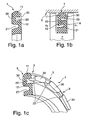
- FIGS. 1 show a sealing ring according to the invention in various, partially perspective, representations.
- a seal 1 according to the invention is in each case inserted to seal a sealing surface 5 between two relatively movable machine parts 6, 7 in a groove 8 in one of the machine parts 7.
- the seal 1 is preferably made in one piece from a rubber-elastic material.
- the sealing body has a nutground document arranged holding part 10, a sealing surface side disposed in the groove 8 sealing part 11 and a resilient connecting part 12 between the sealing part 11 and the holding part 10.
- a recess 20 between the holding part 11 and the connecting part 12 (close to the recess) is formed.
- a further indentation 21 is formed between the connecting part 12 and the sealing part 10 (groove-like indentation).
- spacer elements 25 are formed, which protrude into the recesses 20,21.
- the spacer elements 25 are formed as in the longitudinal direction of the indentations 20,21, that is, in a sealing ring radially extending ribs.
- the sealing surface 5 facing surface of the sealing member 11 a curvature. The degree formed by this curvature forms a sealing lip.
- the pressure equalization channels 3 form pressure equalization paths between the recesses 20,21 and each one arranged on a groove flank of the groove 8 surface of the seal 1, that is, a side surface of the seal 1 from.
- FIGS. 1 show a sealing ring 1 according to the invention with rib-like elevations for forming axial and radial pressure equalization channels 3 in different perspectives.
- the FIG. 1a shows one half of a sealing ring 1 according to the invention prior to its installation in cross-section
- the FIG. 1b shows a half of a seal assembly according to the invention with the built between two mutually movable machine parts 6,7 in a groove 8 sealing ring 1 in cross-section
- Figure 1c shows a part of a three-dimensional representation of the cut-open sealing ring 1.
- the sectional plane of the cross-sectional views is guided in each case through one of the pressure compensation channels 3.
- On the sealing ring 1 radially circumferential groove edge spacers 30 are integrally formed.
- the groove flank spacers 30 present on the near-surface indentation 20 project as an interrupted rib-like elevation into the indentation 20 close to the surface, whereby the groove flank spacers 30 also serve as spacer elements 25.
- the groove flank spacing elements 30 and the spacer elements 25 thus merge into one another and are arranged in the region of the surface of the sealing part 11 on the indentation 20, ie the indentation 20 close to the gasket, or formed on the sealing part 11.
- the pressure compensation channels 3 are formed by interruptions of these groove edge spacers 30.
- the pressure equalization channels 3 extend on the sealing ring 1 in the region of the spacer elements 25 serving as spacer elements 25 in the near-valley recess 20 in the axial direction and extend on the side surface of the sealing ring 1 in the radial direction, ie in the direction of the groove bottom to the sealing surface 5. So there in the radial direction extending pressure equalization channels 3 combined with extending in the axial direction pressure equalization channels 3.
- FIG. 1b It can be seen that the sealing ring 1 in the installed state in the radial direction is pressed together so far that the formed on the sealing member 11 spacer elements 25 abut with its free end on the part formed by the connecting part 12 of the near-surface recess 20. Despite this compressed state, a cavity is formed by the near-valley indentation 20, in which a medium for pressure activation of the sealing ring 1 can flow.
- a seal 1 for sealing a sealing surface 5 between two relatively movable machine parts 6,7, wherein a sealing body of the seal 1 in a groove 8 of the machine parts 7 nutground document to be arranged holding part 10, a sealing surface side in the groove 8 to be arranged sealing member 11 and a resilient connecting part 12 between the sealing part 11 and the holding part 10, and wherein the seal 1 has a formed between the holding part 10 and the connecting part 12 indentation 21 and formed between the connecting part 12 and the sealing part 11 further indentation 20.
- the seal 1 has spacer elements 25, wherein the spacer elements 25 protrude into at least one of the recesses 20, 21, at least the indentation 20 formed between the sealing part 11 and the connecting part 12.
- the invention is not limited to the embodiments given above. Rather, a number of variants are conceivable, which make use of the features of the invention even with fundamentally different type of execution.
Landscapes
- Engineering & Computer Science (AREA)
- General Engineering & Computer Science (AREA)
- Mechanical Engineering (AREA)
- Sealing Devices (AREA)
- Gasket Seals (AREA)
Abstract
Claims (3)
- Joint d'étanchéité annulaire (1) pour étancher une surface d'étanchéité (5) entre deux éléments de machine (6, 7) mobiles l'un par rapport à l'autre,
sachant qu'un corps d'étanchéité du joint d'étanchéité annulaire (1) présente une partie de maintien (10) pouvant être disposée dans une rainure (8), du côté du fond de la rainure, de l'un (7) des éléments de machine, une partie d'étanchéité (11) pouvant être disposée dans la rainure (8) du côté de la surface d'étanchéité, et une partie de liaison souple (12) entre la partie d'étanchéité (11) et la partie de maintien (10),
sachant que le joint d'étanchéité annulaire (1) présente un évidement (21) formé entre la partie de maintien (10) et la partie de liaison (12), et un autre évidement (20) proche de la surface d'étanchéité, formé entre la partie de liaison (12) et la partie d'étanchéité (11),
et sachant que des éléments radialement périphériques (30) d'espacement de flancs de rainure sont formés sur le joint d'étanchéité annulaire,
caractérisé en ce que le joint d'étanchéité annulaire (1) présente des éléments (25) de maintien d'espacement, qui sont prévus au moins dans l'évidement (20) proche de la surface d'étanchéité, formé entre la partie d'étanchéité (11) et la partie de liaison (12),
sachant que les éléments (30) d'espacement de flancs de rainure présents au niveau de l'évidement (20) proche de la surface d'étanchéité s'enfoncent dans l'évidement (20), proche de la surface d'étanchéité, du joint d'étanchéité annulaire (1) sous la forme d'un bossage interrompu du genre nervure et servent en même temps d'éléments (25) de maintien d'espacement, et sachant que les interruptions des éléments (30) d'espacement de flancs de rainure forment des canaux (3) d'égalisation de pression qui s'étendent en direction axiale dans l'évidement (20) proche de la surface d'étanchéité et en direction radiale sur une face supérieure latérale du joint d'étanchéité annulaire (1). - Joint d'étanchéité annulaire selon la revendication 1, caractérisé en ce que les éléments d'espacement de flancs de rainure s'enfoncent dans l'évidement proche de la surface d'étanchéité sur toute l'étendue axiale de l'évidement proche de la surface d'étanchéité.
- Agencement d'étanchéité avec un joint d'étanchéité annulaire (1) selon la revendication 1 ou 2 et avec deux éléments de machine (6, 7) mobiles l'un par rapport à l'autre,
sachant que le joint d'étanchéité annulaire (1) est disposé dans une rainure (8) d'un des deux éléments de machine (6, 7) mobiles l'un par rapport à l'autre.
Applications Claiming Priority (2)
| Application Number | Priority Date | Filing Date | Title |
|---|---|---|---|
| DE102006028467A DE102006028467A1 (de) | 2006-06-21 | 2006-06-21 | Dichtung und Dichtungsanordnung |
| PCT/DE2007/001066 WO2007147391A1 (fr) | 2006-06-21 | 2007-06-15 | Joint et ensemble joint |
Publications (2)
| Publication Number | Publication Date |
|---|---|
| EP2035732A1 EP2035732A1 (fr) | 2009-03-18 |
| EP2035732B1 true EP2035732B1 (fr) | 2012-06-06 |
Family
ID=38476896
Family Applications (1)
| Application Number | Title | Priority Date | Filing Date |
|---|---|---|---|
| EP07764378A Not-in-force EP2035732B1 (fr) | 2006-06-21 | 2007-06-15 | Joint et ensemble joint |
Country Status (8)
| Country | Link |
|---|---|
| US (1) | US8141881B2 (fr) |
| EP (1) | EP2035732B1 (fr) |
| JP (1) | JP5225987B2 (fr) |
| CN (1) | CN101501375B (fr) |
| BR (1) | BRPI0713482B1 (fr) |
| DE (1) | DE102006028467A1 (fr) |
| ES (1) | ES2386881T3 (fr) |
| WO (1) | WO2007147391A1 (fr) |
Families Citing this family (21)
| Publication number | Priority date | Publication date | Assignee | Title |
|---|---|---|---|---|
| JP5081004B2 (ja) * | 2008-01-30 | 2012-11-21 | 日本メクトロン株式会社 | ガスケット |
| JP5892483B2 (ja) * | 2011-06-24 | 2016-03-23 | 株式会社 資生堂 | 化粧料容器 |
| DE102013005711A1 (de) * | 2013-03-30 | 2014-10-02 | Wabco Gmbh | Kolben für ein Druckluft-Steuerventil |
| NO336338B1 (no) * | 2013-06-04 | 2015-08-03 | Seal Eng | Trykkavlastet avskraper |
| US9759330B2 (en) * | 2014-02-04 | 2017-09-12 | Freudenberg-Nok General Partnership | Energy saving seal with rocking dust lip |
| US9695937B2 (en) * | 2014-02-04 | 2017-07-04 | Freudenberg-Nok General Partnership | Energy saving seal with vacuum induced counter-balance and rocking feature |
| US9714710B2 (en) * | 2014-02-04 | 2017-07-25 | Freudenberg-Nok General Partnership | Energy saving self-contact seal with pushing bead |
| JP6483989B2 (ja) * | 2014-10-01 | 2019-03-13 | Ntn株式会社 | シールリング |
| US10344862B2 (en) * | 2015-01-12 | 2019-07-09 | Rolls-Royce Corporation | Shaft coupling seal assembly |
| DE102015101638A1 (de) * | 2015-02-05 | 2016-08-11 | Steffen Dittmar | Dichtungsvorrichtung |
| DE102017202608A1 (de) | 2017-02-17 | 2018-08-23 | Trelleborg Sealing Solutions Germany Gmbh | Dichtungsanordnung mit optimiertem Schmierverhalten |
| DE102017202610A1 (de) * | 2017-02-17 | 2018-08-23 | Trelleborg Sealing Solutions Germany Gmbh | Dichtungsanordnung und Dichtungselement mit hochdruckseitiger Spülfunktion |
| JP6223633B1 (ja) | 2017-03-13 | 2017-11-01 | Tpr株式会社 | シールリングおよび密封装置 |
| AU2017414097B2 (en) * | 2017-05-11 | 2021-05-06 | Valqua, Ltd. | Seal structure |
| CN107763218A (zh) * | 2017-09-04 | 2018-03-06 | 昆明理工大学 | 一种弹性密封圈及圆弧滑动密封装置 |
| US10941829B2 (en) * | 2018-06-29 | 2021-03-09 | Freudenberg-Nok General Partnership | Damper system with a high performance plastic wiper seal |
| JP7325032B2 (ja) * | 2018-12-28 | 2023-08-14 | 株式会社ソミックマネージメントホールディングス | シール体およびロータリダンパ |
| CN110107706B (zh) * | 2019-06-13 | 2024-07-05 | 集美大学 | 一种自清洁插板阀 |
| DE102020129864B4 (de) * | 2020-11-12 | 2025-07-24 | Hanon Systems | Vorrichtung zum Verdichten eines gasförmigen Fluids |
| US11433980B1 (en) * | 2021-01-04 | 2022-09-06 | Brunswick Corporation | Apparatuses for supporting marine drives with respect to marine vessels |
| IT202200009953A1 (it) * | 2022-05-13 | 2023-11-13 | Brembo Spa | Guarnizione primaria per assieme di cilindro, assieme di cilindro |
Family Cites Families (15)
| Publication number | Priority date | Publication date | Assignee | Title |
|---|---|---|---|---|
| DE8405275U1 (de) | 1984-08-09 | Martin Merkel GmbH & Co KG, 2102 Hamburg | Kolben- oder Stangendichtring | |
| BE632658A (fr) * | ||||
| US2188855A (en) * | 1937-10-18 | 1940-01-30 | Timken Roller Bearing Co | Oil seal |
| US2778695A (en) * | 1952-10-09 | 1957-01-22 | Chrysler Corp | Sealing structure |
| FR1298488A (fr) * | 1961-06-01 | 1962-07-13 | Joint d'étanchéité | |
| FR2374575A1 (fr) * | 1976-12-16 | 1978-07-13 | Dunlop Sa | Joint annulaire d'etancheite et ses applications |
| EP0152938A3 (fr) * | 1984-02-21 | 1985-09-25 | Martin Merkel GmbH & Co. KG | Joint d'étanchéité pour piston ou tige de piston |
| DE4141999C2 (de) * | 1991-12-19 | 1997-06-12 | Blohm Voss Ag | Lippendichtung zum Abdichten einer Welle, insbesondere einer Schiffspropellerwelle |
| DE4223671A1 (de) * | 1992-07-17 | 1994-01-20 | Busak & Luyken Gmbh & Co | Dichtungsanordnung |
| US5575484A (en) * | 1995-06-30 | 1996-11-19 | Greene, Tweed Of Delaware, Inc. | Fluid pressure activated piston return spring seal |
| DE29610628U1 (de) | 1996-06-17 | 1997-10-16 | Merkel Dichtelemente GmbH, 21107 Hamburg | Dichtungsanordnung |
| US6290235B1 (en) * | 1997-07-02 | 2001-09-18 | Parker-Hannifin Corporation | Sealing system for a reciprocating shaft |
| DE10154092A1 (de) * | 2001-11-02 | 2003-05-22 | Daimler Chrysler Ag | Radialwellendichtring |
| DE10234542A1 (de) * | 2002-07-30 | 2004-03-04 | Continental Teves Ag & Co. Ohg | Dichtmanschette mit mittlerer Stützrippe |
| DE102006023157B3 (de) * | 2006-05-16 | 2008-01-24 | Trelleborg Sealing Solutions Germany Gmbh | Dichtungsanordnung zur Druckentlastung |
-
2006
- 2006-06-21 DE DE102006028467A patent/DE102006028467A1/de not_active Withdrawn
-
2007
- 2007-06-15 CN CN2007800300964A patent/CN101501375B/zh not_active Expired - Fee Related
- 2007-06-15 ES ES07764378T patent/ES2386881T3/es active Active
- 2007-06-15 WO PCT/DE2007/001066 patent/WO2007147391A1/fr not_active Ceased
- 2007-06-15 JP JP2009515698A patent/JP5225987B2/ja not_active Expired - Fee Related
- 2007-06-15 BR BRPI0713482-7A patent/BRPI0713482B1/pt not_active IP Right Cessation
- 2007-06-15 US US12/308,455 patent/US8141881B2/en not_active Expired - Fee Related
- 2007-06-15 EP EP07764378A patent/EP2035732B1/fr not_active Not-in-force
Also Published As
| Publication number | Publication date |
|---|---|
| JP2009541666A (ja) | 2009-11-26 |
| BRPI0713482B1 (pt) | 2020-01-07 |
| BRPI0713482A2 (pt) | 2012-11-06 |
| EP2035732A1 (fr) | 2009-03-18 |
| DE102006028467A1 (de) | 2008-02-07 |
| US8141881B2 (en) | 2012-03-27 |
| CN101501375B (zh) | 2013-06-05 |
| US20110140368A1 (en) | 2011-06-16 |
| WO2007147391A1 (fr) | 2007-12-27 |
| JP5225987B2 (ja) | 2013-07-03 |
| CN101501375A (zh) | 2009-08-05 |
| ES2386881T3 (es) | 2012-09-04 |
Similar Documents
| Publication | Publication Date | Title |
|---|---|---|
| EP2035732B1 (fr) | Joint et ensemble joint | |
| DE2759943C2 (de) | Dichtungsanordnung für die Kolbenstange eines Stoßdämpfers | |
| EP2027403B1 (fr) | Structure d'étanchéite pour décompression | |
| DE19739472A1 (de) | Dichtungsanordnung | |
| WO2011092111A2 (fr) | Ensemble joint d'étanchéité rotatif | |
| DE102009042142A1 (de) | Ringdichtung für ein Schließglied eines Ventils sowie Dichtungsanordnung mit einer solchen Ringdichtung | |
| EP3872373B1 (fr) | Bague d'étanchéité et son utilisation | |
| DE102018100637B3 (de) | Dichtung und Beschichtungsmittelpumpe mit einer solchen Dichtung | |
| DE102008040996A1 (de) | Dichtungsanordnung | |
| EP3245429B1 (fr) | Système d'étanchéité doté d'élément de décharge de pression et utilisation d'un système d'étanchéité destiné à l'établissement d'une cascade en pression d'espace intermédiaire | |
| EP3149366B1 (fr) | Bague d'étanchéité ou segment racleur | |
| EP1769176A1 (fr) | Ensemble d'etancheite | |
| EP2475915A1 (fr) | Joint annulaire d'élément de fermeture d'une soupape et ensemble d'étanchéité comprenant un tel joint annulaire | |
| DE102011056692A1 (de) | Dichtung mit Druckentlastungsfunktion | |
| DE102011009326A1 (de) | Hydrospeicher und Dichtelement, insbesondere für die Verwendung in einem Hydrospeicher | |
| EP3324083B1 (fr) | Agencement d'étanchéité et son utilisation | |
| EP1762757A1 (fr) | Dispositif de joint d'étanchéité | |
| DE102020121486B3 (de) | Druckmittelzylinder mit statischer Endlagendichtung | |
| EP2653766B1 (fr) | Bague d'équilibrage de pression destinée à être agencée entre deux tubes de creusement d'un pousse-tube souterrain | |
| DE102009036994A1 (de) | Gasfedern mit Rastung | |
| WO2025036915A1 (fr) | Élément de précontrainte constitué de deux matériaux élastomères différents pour la précontrainte radiale d'un joint et dispositif d'étanchéité correspondant | |
| WO2010142645A1 (fr) | Cartouche de gaz avec lubrification à la graisse | |
| WO2007016980A1 (fr) | Joint d'arbre en elastomere | |
| EP1878953A1 (fr) | Dispositif d'étanchéité | |
| DE102020100652A1 (de) | Einsatzdichtung mit rundförmigem Sitz |
Legal Events
| Date | Code | Title | Description |
|---|---|---|---|
| PUAI | Public reference made under article 153(3) epc to a published international application that has entered the european phase |
Free format text: ORIGINAL CODE: 0009012 |
|
| 17P | Request for examination filed |
Effective date: 20090121 |
|
| AK | Designated contracting states |
Kind code of ref document: A1 Designated state(s): AT BE BG CH CY CZ DE DK EE ES FI FR GB GR HU IE IS IT LI LT LU LV MC MT NL PL PT RO SE SI SK TR |
|
| AX | Request for extension of the european patent |
Extension state: AL BA HR MK RS |
|
| 17Q | First examination report despatched |
Effective date: 20091120 |
|
| GRAP | Despatch of communication of intention to grant a patent |
Free format text: ORIGINAL CODE: EPIDOSNIGR1 |
|
| DAX | Request for extension of the european patent (deleted) | ||
| GRAS | Grant fee paid |
Free format text: ORIGINAL CODE: EPIDOSNIGR3 |
|
| GRAA | (expected) grant |
Free format text: ORIGINAL CODE: 0009210 |
|
| AK | Designated contracting states |
Kind code of ref document: B1 Designated state(s): AT BE BG CH CY CZ DE DK EE ES FI FR GB GR HU IE IS IT LI LT LU LV MC MT NL PL PT RO SE SI SK TR |
|
| REG | Reference to a national code |
Ref country code: GB Ref legal event code: FG4D Free format text: NOT ENGLISH |
|
| REG | Reference to a national code |
Ref country code: CH Ref legal event code: EP Ref country code: AT Ref legal event code: REF Ref document number: 561199 Country of ref document: AT Kind code of ref document: T Effective date: 20120615 |
|
| REG | Reference to a national code |
Ref country code: IE Ref legal event code: FG4D Free format text: LANGUAGE OF EP DOCUMENT: GERMAN |
|
| REG | Reference to a national code |
Ref country code: DE Ref legal event code: R096 Ref document number: 502007010006 Country of ref document: DE Effective date: 20120809 |
|
| REG | Reference to a national code |
Ref country code: ES Ref legal event code: FG2A Ref document number: 2386881 Country of ref document: ES Kind code of ref document: T3 Effective date: 20120904 |
|
| REG | Reference to a national code |
Ref country code: NL Ref legal event code: VDEP Effective date: 20120606 |
|
| PG25 | Lapsed in a contracting state [announced via postgrant information from national office to epo] |
Ref country code: FI Free format text: LAPSE BECAUSE OF FAILURE TO SUBMIT A TRANSLATION OF THE DESCRIPTION OR TO PAY THE FEE WITHIN THE PRESCRIBED TIME-LIMIT Effective date: 20120606 Ref country code: CY Free format text: LAPSE BECAUSE OF FAILURE TO SUBMIT A TRANSLATION OF THE DESCRIPTION OR TO PAY THE FEE WITHIN THE PRESCRIBED TIME-LIMIT Effective date: 20120606 Ref country code: SE Free format text: LAPSE BECAUSE OF FAILURE TO SUBMIT A TRANSLATION OF THE DESCRIPTION OR TO PAY THE FEE WITHIN THE PRESCRIBED TIME-LIMIT Effective date: 20120606 Ref country code: LT Free format text: LAPSE BECAUSE OF FAILURE TO SUBMIT A TRANSLATION OF THE DESCRIPTION OR TO PAY THE FEE WITHIN THE PRESCRIBED TIME-LIMIT Effective date: 20120606 |
|
| REG | Reference to a national code |
Ref country code: LT Ref legal event code: MG4D Effective date: 20120606 |
|
| PG25 | Lapsed in a contracting state [announced via postgrant information from national office to epo] |
Ref country code: LV Free format text: LAPSE BECAUSE OF FAILURE TO SUBMIT A TRANSLATION OF THE DESCRIPTION OR TO PAY THE FEE WITHIN THE PRESCRIBED TIME-LIMIT Effective date: 20120606 Ref country code: SI Free format text: LAPSE BECAUSE OF FAILURE TO SUBMIT A TRANSLATION OF THE DESCRIPTION OR TO PAY THE FEE WITHIN THE PRESCRIBED TIME-LIMIT Effective date: 20120606 Ref country code: GR Free format text: LAPSE BECAUSE OF FAILURE TO SUBMIT A TRANSLATION OF THE DESCRIPTION OR TO PAY THE FEE WITHIN THE PRESCRIBED TIME-LIMIT Effective date: 20120907 |
|
| BERE | Be: lapsed |
Owner name: TRELLEBORG SEALING SOLUTIONS GERMANY G.M.B.H. Effective date: 20120630 |
|
| PG25 | Lapsed in a contracting state [announced via postgrant information from national office to epo] |
Ref country code: EE Free format text: LAPSE BECAUSE OF FAILURE TO SUBMIT A TRANSLATION OF THE DESCRIPTION OR TO PAY THE FEE WITHIN THE PRESCRIBED TIME-LIMIT Effective date: 20120606 Ref country code: MC Free format text: LAPSE BECAUSE OF NON-PAYMENT OF DUE FEES Effective date: 20120630 Ref country code: IS Free format text: LAPSE BECAUSE OF FAILURE TO SUBMIT A TRANSLATION OF THE DESCRIPTION OR TO PAY THE FEE WITHIN THE PRESCRIBED TIME-LIMIT Effective date: 20121006 Ref country code: NL Free format text: LAPSE BECAUSE OF FAILURE TO SUBMIT A TRANSLATION OF THE DESCRIPTION OR TO PAY THE FEE WITHIN THE PRESCRIBED TIME-LIMIT Effective date: 20120606 Ref country code: SK Free format text: LAPSE BECAUSE OF FAILURE TO SUBMIT A TRANSLATION OF THE DESCRIPTION OR TO PAY THE FEE WITHIN THE PRESCRIBED TIME-LIMIT Effective date: 20120606 Ref country code: RO Free format text: LAPSE BECAUSE OF FAILURE TO SUBMIT A TRANSLATION OF THE DESCRIPTION OR TO PAY THE FEE WITHIN THE PRESCRIBED TIME-LIMIT Effective date: 20120606 |
|
| REG | Reference to a national code |
Ref country code: CH Ref legal event code: PL |
|
| REG | Reference to a national code |
Ref country code: CH Ref legal event code: PL |
|
| PG25 | Lapsed in a contracting state [announced via postgrant information from national office to epo] |
Ref country code: PT Free format text: LAPSE BECAUSE OF FAILURE TO SUBMIT A TRANSLATION OF THE DESCRIPTION OR TO PAY THE FEE WITHIN THE PRESCRIBED TIME-LIMIT Effective date: 20121008 Ref country code: PL Free format text: LAPSE BECAUSE OF FAILURE TO SUBMIT A TRANSLATION OF THE DESCRIPTION OR TO PAY THE FEE WITHIN THE PRESCRIBED TIME-LIMIT Effective date: 20120606 |
|
| REG | Reference to a national code |
Ref country code: IE Ref legal event code: MM4A |
|
| PLBE | No opposition filed within time limit |
Free format text: ORIGINAL CODE: 0009261 |
|
| STAA | Information on the status of an ep patent application or granted ep patent |
Free format text: STATUS: NO OPPOSITION FILED WITHIN TIME LIMIT |
|
| PG25 | Lapsed in a contracting state [announced via postgrant information from national office to epo] |
Ref country code: BE Free format text: LAPSE BECAUSE OF NON-PAYMENT OF DUE FEES Effective date: 20120630 Ref country code: LI Free format text: LAPSE BECAUSE OF NON-PAYMENT OF DUE FEES Effective date: 20120630 Ref country code: DK Free format text: LAPSE BECAUSE OF FAILURE TO SUBMIT A TRANSLATION OF THE DESCRIPTION OR TO PAY THE FEE WITHIN THE PRESCRIBED TIME-LIMIT Effective date: 20120606 Ref country code: IE Free format text: LAPSE BECAUSE OF NON-PAYMENT OF DUE FEES Effective date: 20120615 Ref country code: CH Free format text: LAPSE BECAUSE OF NON-PAYMENT OF DUE FEES Effective date: 20120630 |
|
| 26N | No opposition filed |
Effective date: 20130307 |
|
| GBPC | Gb: european patent ceased through non-payment of renewal fee |
Effective date: 20120906 |
|
| REG | Reference to a national code |
Ref country code: DE Ref legal event code: R097 Ref document number: 502007010006 Country of ref document: DE Effective date: 20130307 |
|
| REG | Reference to a national code |
Ref country code: HU Ref legal event code: AG4A Ref document number: E015934 Country of ref document: HU |
|
| PG25 | Lapsed in a contracting state [announced via postgrant information from national office to epo] |
Ref country code: MT Free format text: LAPSE BECAUSE OF FAILURE TO SUBMIT A TRANSLATION OF THE DESCRIPTION OR TO PAY THE FEE WITHIN THE PRESCRIBED TIME-LIMIT Effective date: 20120606 Ref country code: BG Free format text: LAPSE BECAUSE OF FAILURE TO SUBMIT A TRANSLATION OF THE DESCRIPTION OR TO PAY THE FEE WITHIN THE PRESCRIBED TIME-LIMIT Effective date: 20120906 Ref country code: GB Free format text: LAPSE BECAUSE OF NON-PAYMENT OF DUE FEES Effective date: 20120906 |
|
| REG | Reference to a national code |
Ref country code: AT Ref legal event code: MM01 Ref document number: 561199 Country of ref document: AT Kind code of ref document: T Effective date: 20120615 |
|
| PG25 | Lapsed in a contracting state [announced via postgrant information from national office to epo] |
Ref country code: AT Free format text: LAPSE BECAUSE OF NON-PAYMENT OF DUE FEES Effective date: 20120615 |
|
| PG25 | Lapsed in a contracting state [announced via postgrant information from national office to epo] |
Ref country code: TR Free format text: LAPSE BECAUSE OF FAILURE TO SUBMIT A TRANSLATION OF THE DESCRIPTION OR TO PAY THE FEE WITHIN THE PRESCRIBED TIME-LIMIT Effective date: 20120606 |
|
| PG25 | Lapsed in a contracting state [announced via postgrant information from national office to epo] |
Ref country code: LU Free format text: LAPSE BECAUSE OF NON-PAYMENT OF DUE FEES Effective date: 20120615 |
|
| REG | Reference to a national code |
Ref country code: FR Ref legal event code: PLFP Year of fee payment: 10 |
|
| REG | Reference to a national code |
Ref country code: FR Ref legal event code: PLFP Year of fee payment: 11 |
|
| REG | Reference to a national code |
Ref country code: FR Ref legal event code: PLFP Year of fee payment: 12 |
|
| PGFP | Annual fee paid to national office [announced via postgrant information from national office to epo] |
Ref country code: CZ Payment date: 20190611 Year of fee payment: 13 Ref country code: IT Payment date: 20190619 Year of fee payment: 13 |
|
| PGFP | Annual fee paid to national office [announced via postgrant information from national office to epo] |
Ref country code: FR Payment date: 20190625 Year of fee payment: 13 Ref country code: HU Payment date: 20190604 Year of fee payment: 13 |
|
| PG25 | Lapsed in a contracting state [announced via postgrant information from national office to epo] |
Ref country code: CZ Free format text: LAPSE BECAUSE OF NON-PAYMENT OF DUE FEES Effective date: 20200615 |
|
| PG25 | Lapsed in a contracting state [announced via postgrant information from national office to epo] |
Ref country code: FR Free format text: LAPSE BECAUSE OF NON-PAYMENT OF DUE FEES Effective date: 20200630 Ref country code: HU Free format text: LAPSE BECAUSE OF NON-PAYMENT OF DUE FEES Effective date: 20200616 |
|
| PG25 | Lapsed in a contracting state [announced via postgrant information from national office to epo] |
Ref country code: IT Free format text: LAPSE BECAUSE OF NON-PAYMENT OF DUE FEES Effective date: 20200615 |
|
| REG | Reference to a national code |
Ref country code: ES Ref legal event code: FD2A Effective date: 20211103 |
|
| PG25 | Lapsed in a contracting state [announced via postgrant information from national office to epo] |
Ref country code: ES Free format text: LAPSE BECAUSE OF NON-PAYMENT OF DUE FEES Effective date: 20200616 |
|
| P01 | Opt-out of the competence of the unified patent court (upc) registered |
Effective date: 20230630 |
|
| PGFP | Annual fee paid to national office [announced via postgrant information from national office to epo] |
Ref country code: DE Payment date: 20240612 Year of fee payment: 18 |
|
| REG | Reference to a national code |
Ref country code: DE Ref legal event code: R119 Ref document number: 502007010006 Country of ref document: DE |