EP2035742B1 - Anordnung für einen zylindrischen tank zum transport von verflüssigten gasen bei niedriger temperatur in einem schiff - Google Patents
Anordnung für einen zylindrischen tank zum transport von verflüssigten gasen bei niedriger temperatur in einem schiff Download PDFInfo
- Publication number
- EP2035742B1 EP2035742B1 EP07747666A EP07747666A EP2035742B1 EP 2035742 B1 EP2035742 B1 EP 2035742B1 EP 07747666 A EP07747666 A EP 07747666A EP 07747666 A EP07747666 A EP 07747666A EP 2035742 B1 EP2035742 B1 EP 2035742B1
- Authority
- EP
- European Patent Office
- Prior art keywords
- tank
- bulkheads
- arrangement according
- support
- cargo
- Prior art date
- Legal status (The legal status is an assumption and is not a legal conclusion. Google has not performed a legal analysis and makes no representation as to the accuracy of the status listed.)
- Not-in-force
Links
- 239000007789 gas Substances 0.000 title claims abstract description 14
- 230000002787 reinforcement Effects 0.000 claims abstract description 16
- 239000003351 stiffener Substances 0.000 claims abstract description 10
- 238000000034 method Methods 0.000 claims abstract description 3
- 238000010276 construction Methods 0.000 claims description 20
- 230000033001 locomotion Effects 0.000 claims description 13
- 239000000463 material Substances 0.000 claims description 9
- 238000012546 transfer Methods 0.000 claims description 9
- 229920000136 polysorbate Polymers 0.000 claims description 5
- 239000012774 insulation material Substances 0.000 claims 1
- 230000001681 protective effect Effects 0.000 claims 1
- 239000003949 liquefied natural gas Substances 0.000 description 8
- 239000012528 membrane Substances 0.000 description 7
- 230000003014 reinforcing effect Effects 0.000 description 6
- 238000013461 design Methods 0.000 description 5
- 229910000831 Steel Inorganic materials 0.000 description 3
- 239000000969 carrier Substances 0.000 description 3
- 238000004519 manufacturing process Methods 0.000 description 3
- 239000010959 steel Substances 0.000 description 3
- 238000009434 installation Methods 0.000 description 2
- 238000009413 insulation Methods 0.000 description 2
- 239000007788 liquid Substances 0.000 description 2
- XAGFODPZIPBFFR-UHFFFAOYSA-N aluminium Chemical compound [Al] XAGFODPZIPBFFR-UHFFFAOYSA-N 0.000 description 1
- 229910052782 aluminium Inorganic materials 0.000 description 1
- 239000004411 aluminium Substances 0.000 description 1
- 230000005540 biological transmission Effects 0.000 description 1
- 238000005520 cutting process Methods 0.000 description 1
- 238000011161 development Methods 0.000 description 1
- 239000011810 insulating material Substances 0.000 description 1
- 238000005259 measurement Methods 0.000 description 1
- 238000005457 optimization Methods 0.000 description 1
- 238000005096 rolling process Methods 0.000 description 1
- 238000007665 sagging Methods 0.000 description 1
- 229910001220 stainless steel Inorganic materials 0.000 description 1
- 239000010935 stainless steel Substances 0.000 description 1
- 230000007704 transition Effects 0.000 description 1
- 238000003466 welding Methods 0.000 description 1
Images


Classifications
-
- F—MECHANICAL ENGINEERING; LIGHTING; HEATING; WEAPONS; BLASTING
- F17—STORING OR DISTRIBUTING GASES OR LIQUIDS
- F17C—VESSELS FOR CONTAINING OR STORING COMPRESSED, LIQUEFIED OR SOLIDIFIED GASES; FIXED-CAPACITY GAS-HOLDERS; FILLING VESSELS WITH, OR DISCHARGING FROM VESSELS, COMPRESSED, LIQUEFIED, OR SOLIDIFIED GASES
- F17C13/00—Details of vessels or of the filling or discharging of vessels
- F17C13/08—Mounting arrangements for vessels
-
- F—MECHANICAL ENGINEERING; LIGHTING; HEATING; WEAPONS; BLASTING
- F17—STORING OR DISTRIBUTING GASES OR LIQUIDS
- F17C—VESSELS FOR CONTAINING OR STORING COMPRESSED, LIQUEFIED OR SOLIDIFIED GASES; FIXED-CAPACITY GAS-HOLDERS; FILLING VESSELS WITH, OR DISCHARGING FROM VESSELS, COMPRESSED, LIQUEFIED, OR SOLIDIFIED GASES
- F17C1/00—Pressure vessels, e.g. gas cylinder, gas tank, replaceable cartridge
- F17C1/02—Pressure vessels, e.g. gas cylinder, gas tank, replaceable cartridge involving reinforcing arrangements
- F17C1/08—Integral reinforcements, e.g. ribs
-
- B—PERFORMING OPERATIONS; TRANSPORTING
- B63—SHIPS OR OTHER WATERBORNE VESSELS; RELATED EQUIPMENT
- B63B—SHIPS OR OTHER WATERBORNE VESSELS; EQUIPMENT FOR SHIPPING
- B63B25/00—Load-accommodating arrangements, e.g. stowing, trimming; Vessels characterised thereby
- B63B25/02—Load-accommodating arrangements, e.g. stowing, trimming; Vessels characterised thereby for bulk goods
- B63B25/08—Load-accommodating arrangements, e.g. stowing, trimming; Vessels characterised thereby for bulk goods fluid
-
- F—MECHANICAL ENGINEERING; LIGHTING; HEATING; WEAPONS; BLASTING
- F17—STORING OR DISTRIBUTING GASES OR LIQUIDS
- F17C—VESSELS FOR CONTAINING OR STORING COMPRESSED, LIQUEFIED OR SOLIDIFIED GASES; FIXED-CAPACITY GAS-HOLDERS; FILLING VESSELS WITH, OR DISCHARGING FROM VESSELS, COMPRESSED, LIQUEFIED, OR SOLIDIFIED GASES
- F17C13/00—Details of vessels or of the filling or discharging of vessels
- F17C13/02—Special adaptations of indicating, measuring, or monitoring equipment
-
- F—MECHANICAL ENGINEERING; LIGHTING; HEATING; WEAPONS; BLASTING
- F17—STORING OR DISTRIBUTING GASES OR LIQUIDS
- F17C—VESSELS FOR CONTAINING OR STORING COMPRESSED, LIQUEFIED OR SOLIDIFIED GASES; FIXED-CAPACITY GAS-HOLDERS; FILLING VESSELS WITH, OR DISCHARGING FROM VESSELS, COMPRESSED, LIQUEFIED, OR SOLIDIFIED GASES
- F17C2201/00—Vessel construction, in particular geometry, arrangement or size
- F17C2201/01—Shape
- F17C2201/0104—Shape cylindrical
- F17C2201/0109—Shape cylindrical with exteriorly curved end-piece
-
- F—MECHANICAL ENGINEERING; LIGHTING; HEATING; WEAPONS; BLASTING
- F17—STORING OR DISTRIBUTING GASES OR LIQUIDS
- F17C—VESSELS FOR CONTAINING OR STORING COMPRESSED, LIQUEFIED OR SOLIDIFIED GASES; FIXED-CAPACITY GAS-HOLDERS; FILLING VESSELS WITH, OR DISCHARGING FROM VESSELS, COMPRESSED, LIQUEFIED, OR SOLIDIFIED GASES
- F17C2201/00—Vessel construction, in particular geometry, arrangement or size
- F17C2201/03—Orientation
- F17C2201/035—Orientation with substantially horizontal main axis
-
- F—MECHANICAL ENGINEERING; LIGHTING; HEATING; WEAPONS; BLASTING
- F17—STORING OR DISTRIBUTING GASES OR LIQUIDS
- F17C—VESSELS FOR CONTAINING OR STORING COMPRESSED, LIQUEFIED OR SOLIDIFIED GASES; FIXED-CAPACITY GAS-HOLDERS; FILLING VESSELS WITH, OR DISCHARGING FROM VESSELS, COMPRESSED, LIQUEFIED, OR SOLIDIFIED GASES
- F17C2201/00—Vessel construction, in particular geometry, arrangement or size
- F17C2201/05—Size
- F17C2201/052—Size large (>1000 m3)
-
- F—MECHANICAL ENGINEERING; LIGHTING; HEATING; WEAPONS; BLASTING
- F17—STORING OR DISTRIBUTING GASES OR LIQUIDS
- F17C—VESSELS FOR CONTAINING OR STORING COMPRESSED, LIQUEFIED OR SOLIDIFIED GASES; FIXED-CAPACITY GAS-HOLDERS; FILLING VESSELS WITH, OR DISCHARGING FROM VESSELS, COMPRESSED, LIQUEFIED, OR SOLIDIFIED GASES
- F17C2203/00—Vessel construction, in particular walls or details thereof
- F17C2203/01—Reinforcing or suspension means
- F17C2203/011—Reinforcing means
- F17C2203/012—Reinforcing means on or in the wall, e.g. ribs
-
- F—MECHANICAL ENGINEERING; LIGHTING; HEATING; WEAPONS; BLASTING
- F17—STORING OR DISTRIBUTING GASES OR LIQUIDS
- F17C—VESSELS FOR CONTAINING OR STORING COMPRESSED, LIQUEFIED OR SOLIDIFIED GASES; FIXED-CAPACITY GAS-HOLDERS; FILLING VESSELS WITH, OR DISCHARGING FROM VESSELS, COMPRESSED, LIQUEFIED, OR SOLIDIFIED GASES
- F17C2203/00—Vessel construction, in particular walls or details thereof
- F17C2203/01—Reinforcing or suspension means
- F17C2203/011—Reinforcing means
- F17C2203/013—Reinforcing means in the vessel, e.g. columns
-
- F—MECHANICAL ENGINEERING; LIGHTING; HEATING; WEAPONS; BLASTING
- F17—STORING OR DISTRIBUTING GASES OR LIQUIDS
- F17C—VESSELS FOR CONTAINING OR STORING COMPRESSED, LIQUEFIED OR SOLIDIFIED GASES; FIXED-CAPACITY GAS-HOLDERS; FILLING VESSELS WITH, OR DISCHARGING FROM VESSELS, COMPRESSED, LIQUEFIED, OR SOLIDIFIED GASES
- F17C2203/00—Vessel construction, in particular walls or details thereof
- F17C2203/01—Reinforcing or suspension means
- F17C2203/014—Suspension means
- F17C2203/015—Bars
-
- F—MECHANICAL ENGINEERING; LIGHTING; HEATING; WEAPONS; BLASTING
- F17—STORING OR DISTRIBUTING GASES OR LIQUIDS
- F17C—VESSELS FOR CONTAINING OR STORING COMPRESSED, LIQUEFIED OR SOLIDIFIED GASES; FIXED-CAPACITY GAS-HOLDERS; FILLING VESSELS WITH, OR DISCHARGING FROM VESSELS, COMPRESSED, LIQUEFIED, OR SOLIDIFIED GASES
- F17C2203/00—Vessel construction, in particular walls or details thereof
- F17C2203/03—Thermal insulations
- F17C2203/0304—Thermal insulations by solid means
-
- F—MECHANICAL ENGINEERING; LIGHTING; HEATING; WEAPONS; BLASTING
- F17—STORING OR DISTRIBUTING GASES OR LIQUIDS
- F17C—VESSELS FOR CONTAINING OR STORING COMPRESSED, LIQUEFIED OR SOLIDIFIED GASES; FIXED-CAPACITY GAS-HOLDERS; FILLING VESSELS WITH, OR DISCHARGING FROM VESSELS, COMPRESSED, LIQUEFIED, OR SOLIDIFIED GASES
- F17C2203/00—Vessel construction, in particular walls or details thereof
- F17C2203/06—Materials for walls or layers thereof; Properties or structures of walls or their materials
- F17C2203/0602—Wall structures; Special features thereof
- F17C2203/0612—Wall structures
- F17C2203/0614—Single wall
- F17C2203/0617—Single wall with one layer
-
- F—MECHANICAL ENGINEERING; LIGHTING; HEATING; WEAPONS; BLASTING
- F17—STORING OR DISTRIBUTING GASES OR LIQUIDS
- F17C—VESSELS FOR CONTAINING OR STORING COMPRESSED, LIQUEFIED OR SOLIDIFIED GASES; FIXED-CAPACITY GAS-HOLDERS; FILLING VESSELS WITH, OR DISCHARGING FROM VESSELS, COMPRESSED, LIQUEFIED, OR SOLIDIFIED GASES
- F17C2203/00—Vessel construction, in particular walls or details thereof
- F17C2203/06—Materials for walls or layers thereof; Properties or structures of walls or their materials
- F17C2203/0634—Materials for walls or layers thereof
- F17C2203/0636—Metals
- F17C2203/0639—Steels
- F17C2203/0643—Stainless steels
-
- F—MECHANICAL ENGINEERING; LIGHTING; HEATING; WEAPONS; BLASTING
- F17—STORING OR DISTRIBUTING GASES OR LIQUIDS
- F17C—VESSELS FOR CONTAINING OR STORING COMPRESSED, LIQUEFIED OR SOLIDIFIED GASES; FIXED-CAPACITY GAS-HOLDERS; FILLING VESSELS WITH, OR DISCHARGING FROM VESSELS, COMPRESSED, LIQUEFIED, OR SOLIDIFIED GASES
- F17C2203/00—Vessel construction, in particular walls or details thereof
- F17C2203/06—Materials for walls or layers thereof; Properties or structures of walls or their materials
- F17C2203/0634—Materials for walls or layers thereof
- F17C2203/0636—Metals
- F17C2203/0646—Aluminium
-
- F—MECHANICAL ENGINEERING; LIGHTING; HEATING; WEAPONS; BLASTING
- F17—STORING OR DISTRIBUTING GASES OR LIQUIDS
- F17C—VESSELS FOR CONTAINING OR STORING COMPRESSED, LIQUEFIED OR SOLIDIFIED GASES; FIXED-CAPACITY GAS-HOLDERS; FILLING VESSELS WITH, OR DISCHARGING FROM VESSELS, COMPRESSED, LIQUEFIED, OR SOLIDIFIED GASES
- F17C2205/00—Vessel construction, in particular mounting arrangements, attachments or identifications means
- F17C2205/01—Mounting arrangements
- F17C2205/0103—Exterior arrangements
- F17C2205/0119—Vessel walls form part of another structure
-
- F—MECHANICAL ENGINEERING; LIGHTING; HEATING; WEAPONS; BLASTING
- F17—STORING OR DISTRIBUTING GASES OR LIQUIDS
- F17C—VESSELS FOR CONTAINING OR STORING COMPRESSED, LIQUEFIED OR SOLIDIFIED GASES; FIXED-CAPACITY GAS-HOLDERS; FILLING VESSELS WITH, OR DISCHARGING FROM VESSELS, COMPRESSED, LIQUEFIED, OR SOLIDIFIED GASES
- F17C2205/00—Vessel construction, in particular mounting arrangements, attachments or identifications means
- F17C2205/01—Mounting arrangements
- F17C2205/0123—Mounting arrangements characterised by number of vessels
- F17C2205/013—Two or more vessels
- F17C2205/0134—Two or more vessels characterised by the presence of fluid connection between vessels
-
- F—MECHANICAL ENGINEERING; LIGHTING; HEATING; WEAPONS; BLASTING
- F17—STORING OR DISTRIBUTING GASES OR LIQUIDS
- F17C—VESSELS FOR CONTAINING OR STORING COMPRESSED, LIQUEFIED OR SOLIDIFIED GASES; FIXED-CAPACITY GAS-HOLDERS; FILLING VESSELS WITH, OR DISCHARGING FROM VESSELS, COMPRESSED, LIQUEFIED, OR SOLIDIFIED GASES
- F17C2205/00—Vessel construction, in particular mounting arrangements, attachments or identifications means
- F17C2205/03—Fluid connections, filters, valves, closure means or other attachments
- F17C2205/0302—Fittings, valves, filters, or components in connection with the gas storage device
- F17C2205/0379—Manholes or access openings for human beings
-
- F—MECHANICAL ENGINEERING; LIGHTING; HEATING; WEAPONS; BLASTING
- F17—STORING OR DISTRIBUTING GASES OR LIQUIDS
- F17C—VESSELS FOR CONTAINING OR STORING COMPRESSED, LIQUEFIED OR SOLIDIFIED GASES; FIXED-CAPACITY GAS-HOLDERS; FILLING VESSELS WITH, OR DISCHARGING FROM VESSELS, COMPRESSED, LIQUEFIED, OR SOLIDIFIED GASES
- F17C2209/00—Vessel construction, in particular methods of manufacturing
- F17C2209/22—Assembling processes
- F17C2209/221—Welding
-
- F—MECHANICAL ENGINEERING; LIGHTING; HEATING; WEAPONS; BLASTING
- F17—STORING OR DISTRIBUTING GASES OR LIQUIDS
- F17C—VESSELS FOR CONTAINING OR STORING COMPRESSED, LIQUEFIED OR SOLIDIFIED GASES; FIXED-CAPACITY GAS-HOLDERS; FILLING VESSELS WITH, OR DISCHARGING FROM VESSELS, COMPRESSED, LIQUEFIED, OR SOLIDIFIED GASES
- F17C2221/00—Handled fluid, in particular type of fluid
- F17C2221/03—Mixtures
- F17C2221/032—Hydrocarbons
- F17C2221/033—Methane, e.g. natural gas, CNG, LNG, GNL, GNC, PLNG
-
- F—MECHANICAL ENGINEERING; LIGHTING; HEATING; WEAPONS; BLASTING
- F17—STORING OR DISTRIBUTING GASES OR LIQUIDS
- F17C—VESSELS FOR CONTAINING OR STORING COMPRESSED, LIQUEFIED OR SOLIDIFIED GASES; FIXED-CAPACITY GAS-HOLDERS; FILLING VESSELS WITH, OR DISCHARGING FROM VESSELS, COMPRESSED, LIQUEFIED, OR SOLIDIFIED GASES
- F17C2223/00—Handled fluid before transfer, i.e. state of fluid when stored in the vessel or before transfer from the vessel
- F17C2223/01—Handled fluid before transfer, i.e. state of fluid when stored in the vessel or before transfer from the vessel characterised by the phase
- F17C2223/0146—Two-phase
- F17C2223/0153—Liquefied gas, e.g. LPG, GPL
- F17C2223/0161—Liquefied gas, e.g. LPG, GPL cryogenic, e.g. LNG, GNL, PLNG
-
- F—MECHANICAL ENGINEERING; LIGHTING; HEATING; WEAPONS; BLASTING
- F17—STORING OR DISTRIBUTING GASES OR LIQUIDS
- F17C—VESSELS FOR CONTAINING OR STORING COMPRESSED, LIQUEFIED OR SOLIDIFIED GASES; FIXED-CAPACITY GAS-HOLDERS; FILLING VESSELS WITH, OR DISCHARGING FROM VESSELS, COMPRESSED, LIQUEFIED, OR SOLIDIFIED GASES
- F17C2223/00—Handled fluid before transfer, i.e. state of fluid when stored in the vessel or before transfer from the vessel
- F17C2223/03—Handled fluid before transfer, i.e. state of fluid when stored in the vessel or before transfer from the vessel characterised by the pressure level
- F17C2223/033—Small pressure, e.g. for liquefied gas
-
- F—MECHANICAL ENGINEERING; LIGHTING; HEATING; WEAPONS; BLASTING
- F17—STORING OR DISTRIBUTING GASES OR LIQUIDS
- F17C—VESSELS FOR CONTAINING OR STORING COMPRESSED, LIQUEFIED OR SOLIDIFIED GASES; FIXED-CAPACITY GAS-HOLDERS; FILLING VESSELS WITH, OR DISCHARGING FROM VESSELS, COMPRESSED, LIQUEFIED, OR SOLIDIFIED GASES
- F17C2250/00—Accessories; Control means; Indicating, measuring or monitoring of parameters
- F17C2250/04—Indicating or measuring of parameters as input values
- F17C2250/0404—Parameters indicated or measured
- F17C2250/043—Pressure
-
- F—MECHANICAL ENGINEERING; LIGHTING; HEATING; WEAPONS; BLASTING
- F17—STORING OR DISTRIBUTING GASES OR LIQUIDS
- F17C—VESSELS FOR CONTAINING OR STORING COMPRESSED, LIQUEFIED OR SOLIDIFIED GASES; FIXED-CAPACITY GAS-HOLDERS; FILLING VESSELS WITH, OR DISCHARGING FROM VESSELS, COMPRESSED, LIQUEFIED, OR SOLIDIFIED GASES
- F17C2250/00—Accessories; Control means; Indicating, measuring or monitoring of parameters
- F17C2250/04—Indicating or measuring of parameters as input values
- F17C2250/0486—Indicating or measuring characterised by the location
- F17C2250/0491—Parameters measured at or inside the vessel
-
- F—MECHANICAL ENGINEERING; LIGHTING; HEATING; WEAPONS; BLASTING
- F17—STORING OR DISTRIBUTING GASES OR LIQUIDS
- F17C—VESSELS FOR CONTAINING OR STORING COMPRESSED, LIQUEFIED OR SOLIDIFIED GASES; FIXED-CAPACITY GAS-HOLDERS; FILLING VESSELS WITH, OR DISCHARGING FROM VESSELS, COMPRESSED, LIQUEFIED, OR SOLIDIFIED GASES
- F17C2260/00—Purposes of gas storage and gas handling
- F17C2260/01—Improving mechanical properties or manufacturing
- F17C2260/011—Improving strength
-
- F—MECHANICAL ENGINEERING; LIGHTING; HEATING; WEAPONS; BLASTING
- F17—STORING OR DISTRIBUTING GASES OR LIQUIDS
- F17C—VESSELS FOR CONTAINING OR STORING COMPRESSED, LIQUEFIED OR SOLIDIFIED GASES; FIXED-CAPACITY GAS-HOLDERS; FILLING VESSELS WITH, OR DISCHARGING FROM VESSELS, COMPRESSED, LIQUEFIED, OR SOLIDIFIED GASES
- F17C2260/00—Purposes of gas storage and gas handling
- F17C2260/01—Improving mechanical properties or manufacturing
- F17C2260/016—Preventing slosh
-
- F—MECHANICAL ENGINEERING; LIGHTING; HEATING; WEAPONS; BLASTING
- F17—STORING OR DISTRIBUTING GASES OR LIQUIDS
- F17C—VESSELS FOR CONTAINING OR STORING COMPRESSED, LIQUEFIED OR SOLIDIFIED GASES; FIXED-CAPACITY GAS-HOLDERS; FILLING VESSELS WITH, OR DISCHARGING FROM VESSELS, COMPRESSED, LIQUEFIED, OR SOLIDIFIED GASES
- F17C2260/00—Purposes of gas storage and gas handling
- F17C2260/01—Improving mechanical properties or manufacturing
- F17C2260/017—Improving mechanical properties or manufacturing by calculation
-
- F—MECHANICAL ENGINEERING; LIGHTING; HEATING; WEAPONS; BLASTING
- F17—STORING OR DISTRIBUTING GASES OR LIQUIDS
- F17C—VESSELS FOR CONTAINING OR STORING COMPRESSED, LIQUEFIED OR SOLIDIFIED GASES; FIXED-CAPACITY GAS-HOLDERS; FILLING VESSELS WITH, OR DISCHARGING FROM VESSELS, COMPRESSED, LIQUEFIED, OR SOLIDIFIED GASES
- F17C2270/00—Applications
- F17C2270/01—Applications for fluid transport or storage
- F17C2270/0102—Applications for fluid transport or storage on or in the water
- F17C2270/0105—Ships
Definitions
- the present invention relates to design, construction and support of large, independent, horizontal and generally cylindrical tanks onboard ships, and for the transportation of liquefied gases at low temperatures.
- the invention is also in principle applicable for so-called twin tanks consisting of two cylindrical tanks built together into one common tank.
- Horizontal and independent cylindrical tanks have to a large extent been used for ships with relatively small total cargo capacity for transportation of liquefied gases at low temperatures, and the largest known and built ship with such cargo tanks has a total cargo capacity of about 30.000 m 3 .
- independent cylindrical tanks have not been applied for the largest ships for liquefied gases, notwithstanding that with regard to design, fabrication and installation onboard ships, such cylindrical tanks should be preferable, for example as compared to spherical tanks.
- a spherical tank has only one degree of freedom (diameter), while a cylindrical tank has two degrees of freedom (diameter and length) which favours the arrangement and installation in a surrounding hull.
- the number of cargo tanks is a significant parameter for the costs for building of ships for LNG. It may be worth mentioning that for the largest ships under contract and construction, it has been necessary to increase the number of cargo tanks from four to five (compared to membrane ships of somewhat smaller size), and the ships have become relatively more expensive to build.
- a common weakness/disadvantage of LNG ships of the membrane and spherical tank types is the arrangement for pipes, electric cables and internal access between the top and bottom of cargo tanks.
- the distance between top and bottom can be in the range of 40-45 metres, and a freestanding tower has to be provided inside each cargo tank for supporting and clamping of pipes and cables, as well as for ladders for access to the bottom of the tank.
- a conceivable alternative for applying independent cylindrical tanks for the large and largest ships for transportation of liquefied gases could be an upscaling of existing constructions of applied cylindrical tanks for smaller types of liquefied gas carriers.
- the independent cylindrical tanks are supported in two saddle constructions, such saddle constructions being integrated in surrounding hull constructions.
- cargo tank either made of aluminium, stainless steel or low-temperature steel
- the saddle construction of steel there is provided a thermal insulating material of sufficient strength to carry the weight of a full cargo tank.
- the critical load points for such cylindrical tanks will be at the supports and at shell and internal reinforcements in way of the supports.
- the internal reinforcements for the smaller type of ships/tanks consist normally of
- Such kinds of reinforcements are sufficient for rather small and medium sized liquefied gas carriers, and restrictions for filling level in such smaller cargo tanks are normally not necessary. Examples of both reinforcements are shown in GB 2032506 A , which is the closest prior art upon which the preamble of the independent claim 1 is based.
- the present invention is providing technical solutions enabling application of large independent cylindrical tanks for transportation of liquefied gases, and especially liquefied natural gas (LNG). Furthermore, the present invention alleviates the above-mentioned major weaknesses/disadvantages of other design concepts.
- An arrangement according to the invention is defined in claim 1 and a method according to the invention is defined in claim 12.
- the invention is providing good technical solutions for the following important items:
- the present invention are providing constructions/reinforcements internally in the tanks at the supports enabling exact stress calculations in materials for cargo tanks and surrounding hull structures at the prevailing load conditions.
- the invention consists mainly of providing two perforated circular wash bulkheads beside one other internally in the cargo tank at each support.
- the distance between the circular wash bulkheads will normally be in the range of 1 - 4 metres.
- a framework of girders/stiffeners will be provided and welded, and such that the two circular perforated bulkheads will be connected to each other through a framework.
- the adjacent sections of external shell plates will subsequently be welded to the periphery of the circular perforated bulkheads and to the radial girders between the bulkheads.
- the two circular perforated bulkheads, the between-lying framework and the external shell plates will accordingly constitute a rigid wheel-like construction.
- the two circular bulkheads in the construction will have many openings/perforations for quick balancing of differences in levels within the tank.
- the two circular and perforated bulkheads together with intermediate framework and external shell will be a very strong construction.
- the radial and global stiffness can be made almost infinite, and it will be almost impossible to have any global or local radial deformation of the tank at the prevailing external loads.
- the space between the two circular and perforated bulkheads at each support can in an efficient manner be used for pipes, cables and access between top and bottom of the tank.
- a dome for connection of pipes and cables and with an access hatch is arranged straight above the double bulkhead.
- the cargo tanks have ambient temperature when installed and adapted to the saddle support constructions of the hull.
- cargo e.g. LNG
- the diameter of the tanks will shrink about 60 mm in diameter for a steel tank of 30 meter diameter.
- the tank might partially deviate from the original contact surface to the saddle support, and the subsequent risk for the tank to become unstable in the transverse direction when the ship is rolling in the sea, cannot be neglected.
- domes above the double wash bulkhead makes it possible to arrange internal stiffening plates in the dome, as well as to arrange external brackets at the domes in plane with the wash bulkheads.
- This enables the structures of the domes, as connected to the circular wash bulkheads, to withstand all prevailing transverse force and to transfer the forces to the surrounding deck structures.
- the transfer of transverse forces from the cargo tank via the dome to the surrounding deck structure is permitted by a system of a specially arranged insulating 'tween material between domes and deck structures.
- the arrangement of the 'tween material is also taking care of required vertical and longitudinal movements due to temperature changes of the cargo tank.
- the required possibility for vertical movement of cargo tank is arranged.
- the required possibility for vertical and longitudinal movements is arranged. If the ship is prone to sagging and hogging, also the aft dome may permit some longitudinal movement.
- An additional advantage of the present design concept is the possibility for production of the cylindrical sections at the supports with built-in bulkheads/frameworks with exact roundness.
- the circular and perforated bulkheads can be constructed and fully welded, and initially made with excess measurements. Upon final weldings, the bulkheads might be measured, marked and cut to the exact desired diameter, and exact circular roundness can be achieved and guaranteed.
- the adjacent shell plates can be welded to the circular and perforated bulkheads and adjoining frameworks, and exact roundness is still maintained.
- Another new proposed item is the application of pressure sensors along the periphery of saddle constructions between tank and hull. Pressure loads on saddles can be monitored continuously, and can also be compared with pre-calculated loads along the periphery of the support system.
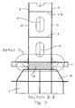
- Fig. 1A and 1B show a general arrangement plan for a LNG-carrier 1 of about 145.000 m 3 total cargo capacity, and with three 3 cylindrical cargo tanks.
- Fig.2A and Fig.2B show a transverse section through the ship and through a cargo tank (see Fig.1A Section A-A), and the section is shown between the perforated bulkheads 3 at one of the supports for one cargo tank.
- the figures show two alternative arrangements/solutions for frameworks between the circular and perforated bulkheads.
- the between-lying framework shown in Fig.2A consists of vertical 4 and horizontal 5 plate girders.
- the between-lying framework shown in Fig.2B consists of concentric ring girders 6 and radial girders 7.
- both figures/alternatives show that the cargo tanks are provided with external thermal insulation 11, saddle supports 12 and an insulating and a weight-bearing material between saddle support and cargo tank 13.
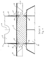
- Fig. 3 show section B-13 as indicated on Fig.2A and Fig.2B , and show the two perforated bulkheads 3 at a certain distance from each other. This distance is previously indicated to be in the range of 1-4 metres.
- the figure shows as well the principle for locking the tank at the saddle support against movement in longitudinal direction at one of the supports. At the other support, the tank 2 is free to slide in longitudinal direction.
- Fig. 3 also shows that vertical and horizontal girders (including concentric girders) are provided with openings 10 and 14 for free flow of liquid cargo, and for access to all spaces between the circular bulkheads.
- vertical and horizontal girders including concentric girders
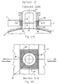
- Fig.4 shows Detail 3 as referred to on Fig.3 , and shows arrangement for transfer of forces (mainly because of sloshing) in longitudinal direction from bulkheads 3 and radial plates 7 to the external shell plates 17.
- bracket 15 Internally in the tank is shown bracket 15 at transition between bulkhead 3 and shell 17, and externally in same plane is shown bracket 16. Both these brackets is sniped and grounded towards zero at the termination towards shell. Furthermore, external brackets 18 are shown in the support zone, and in same radial plane as other brackets 15 and 16 and internal radial plate 7. Arrangement of last-mentioned bracket 18 is characterized by cutting of space for the bracket in the 'tween material 13 between tank and saddle support. For locking of the tank in longitudinal direction, flat bars 19 are arranged externally along the periphery in the support zone of the tank.
- Corresponding flat bars 20 are arranged on the saddle support 12 for locking of the 'tween material 13 to the saddle support 12 and to the surrounding hull 1.
- Fig. 5A and Fig. 5B of Detail 1 as referred to on Fig.1A show the principle for locking the tank 2 in transverse and longitudinal directions at aft dome 23.
- the concentric ring 21 are fixed to the hull 1
- concentric ring 22 are fixed to the aft dome 23, and the surface between the concentric rings will act as sliding surface for vertical movements of the aft dome 23 due to changes in temperature of the tank 2.
- Material quality for these concentric rings might be same as applied between cargo tank and saddle support.
- the aft dome 23 and the tank 2 is locked for movements in transverse and longitudinal directions, and the dynamic forces on the cargo tank 2 when the ship is at sea, are transferred from the tank 2 via the aft dome 23 and concentric rings 21 and 22 to the hull 1.
- the aft dome 23 is internally reinforced by vertical reinforcing plates 24, and horizontal reinforcing plates 25.
- the vertical reinforcing plates 24 are assumed to be arranged in same plane as the two circular wash bulkheads 3, and in same plane is as well arranged brackets 26 between aft dome 23 and shell plates 17 of the tank for reducing stress concentrations at the transfer of forces.
- Fig. 5B shows mainly Section C - C as indicated in Fig. 5A .
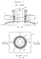
- Fig. 6A and Fig. 6B of Detail 2 as referred to on Fig. 1A show the principle at forward dome 29 for locking the tank 2 in transverse direction, and at the same time to secure free movement of forward dome 29 and the tank 2 in vertical and longitudinal directions due to temperature changes.
- the intermediate elements 27 and 28 are arranged between forward dome and the surrounding hull 1.
- the inner element 27 is fixed to the dome, and the outer elements 28 (two separate pieces) are fixed to the hull 1, and the joint surfaces of the inner element 27 and the outer elements 28 are acting as sliding surfaces for vertical and longitudinal movements of the forward dome 29 due to changes in temperature of the tank 2. Material quality for these intermediate elements might be same as applied between cargo tank and saddle support.
- the forward dome 29 and the tank 2 is locked for movements in transverse direction, and the dynamic transverse forces on the cargo tank 2 are transferred from the tank 2 via the forward dome 29 and intermediate elements 27 and 28 to the hull 1.
- the forward dome 29 is internally reinforced by vertical reinforcing plates 30, and horizontal reinforcing plates 31.
- the vertical reinforcing plates 30 are assumed to be arranged in same plane as the two circular wash bulkheads 3,
- brackets 32 between forward dome 29 and shell plates 17 of the tank for reducing stress concentrations at the transfer of forces.
- Fig. 6B shows mainly Section D - D as indicated in Fig. 6A .
Landscapes
- Engineering & Computer Science (AREA)
- Mechanical Engineering (AREA)
- General Engineering & Computer Science (AREA)
- Chemical & Material Sciences (AREA)
- Combustion & Propulsion (AREA)
- Ocean & Marine Engineering (AREA)
- Filling Or Discharging Of Gas Storage Vessels (AREA)
- Supply Devices, Intensifiers, Converters, And Telemotors (AREA)
- Surgical Instruments (AREA)
Claims (12)
- Anordnung für einen waagerechten und im Allgemeinen zylindrischen Tank (2) zum Transport von Flüssiggasen bei niedriger Temperatur auf Schiffen, wobei der Tank (2) auf dem Schiff in mindestens zwei Trägern (12) getragen wird, und wobei der Tank eine interne Verstärkung aufweist, die ein perforiertes und versteiftes Schott an jedem Träger umfasst,
dadurch gekennzeichnet, dass die interne Verstärkung an jedem Träger zwei angrenzende kreisförmige und perforierte Schotte (3) mit einem Zwischenraum dazwischen umfasst, und dass ein Rahmenbausystem aus gekreuzten Aussteifungen (4 bis 7) angeordnet und an die angrenzenden Schotte in dem Zwischenraum angeschweißt ist. - Anordnung nach Anspruch 1, wobei eine hintere Kuppel (23) zusammen mit den beiden angrenzenden kreisförmigen und perforierten Schotten (3) an einem hinteren Ladetanksattelträger angeordnet ist, um es der hinteren Kuppel durch interne Verstärkungen (24, 25) und externe Stützen (26) in Reihe mit den Schotten (3) zu ermöglichen, Quer- und Längskräfte zwischen dem Ladetank (2) über Zwischenelemente (22, 23) auf den Rumpf (1) zu übertragen, und es der hinteren Kuppel (23) gleichzeitig zu ermöglichen, in der senkrechten Richtung zu gleiten.
- Anordnung nach Anspruch 1 oder 2, wobei eine vordere Kuppel (29) zusammen mit den beiden angrenzenden kreisförmigen und perforierten Schotten (3) an einem vorderen Ladetanksattelträger angeordnet ist, um es der vorderen Kuppel durch interne Verstärkungen (30) und externe Stützen (32) in Reihe mit den Schotten (3) zu ermöglichen, Querkräfte zwischen dem Ladetank (2) über Zwischenelemente (27, 28) auf den Rumpf (1) zu übertragen, und es der vorderen Kuppel (29) gleichzeitig zu ermöglichen, in der senkrechten Richtung und der Längsrichtung zu gleiten.
- Anordnung nach Anspruch 1, wobei die Schotte (3) Öffnungsbereiche (10) des jeweiligen Schotts aufweisen, die durch die nächstgelegenen Balken (4 bis 7) begrenzt sind.
- Anordnung nach Anspruch 1 oder 4, wobei der Raum zwischen den Schotten (3) zum geschützten Durchgang von Rohren und elektrischen Kabeln (9) verwendet wird, und um Zugriff (8) zwischen dem Oberteil und dem Unterteil des Tanks bereitzustellen.
- Anordnung nach Anspruch 1, 4 oder 5, wobei die Aussteifungen tangential und radial orientierte Platten (6, 7) umfassen.
- Anordnung nach Anspruch 6, wobei die Aussteifungen ebenfalls senkrechte und waagerechte Platten (4, 5) umfassen.
- Anordnung nach Anspruch 6 oder 7, wobei mindestens einige der Aussteifungsplatten (4 bis 7) mit Öffnungen (14) versehen sind.
- Anordnung nach einem der vorhergehenden Ansprüche, wobei das Tragsystem ein sattelartiger Träger (12) mit einem Lagerisoliermaterial (13) der gleichen Länge wie der Abstand zwischen den internen Schotten (3) ist, wobei das Zwischenmaterial (13) durch flache Stangenflansche (19), die an dem Mantel (17) des Tanks (2) angeschweißt und mit Stützen (16, 18) verstärkt sind, die bevorzugt geschellt sind, gegen Bewegung blockiert ist, wobei geschellte Stützen (15) auch zwischen dem Mantel (17) des Tanks (2) und den Schotten (3) bereitgestellt werden.
- Anordnung nach Anspruch 9, wobei Drucksensoren bereitgestellt werden und an dem Umfang des Trägersystems entlang angeordnet sind, wobei der senkrechte Druck von dem Tank auf die Träger durchgehend überwacht und aufgezeichnet wird.
- Anordnung nach einem der vorhergehenden Ansprüche, wobei der Tank (2) ein Ladevolumen im Bereich von 40.000 bis 60.000 m3 aufweist, und wobei der Abstand zwischen den angrenzenden Schotten (3) an einem Träger bevorzugt in dem Bereich von 1 bis 4 Metern liegt.
- Verfahren zur Konstruktion eines im Allgemeinen zylindrischen Tanks zum Transport von Flüssiggasen bei niedriger Temperatur auf Schiffen, wobei der Tank (2) mit mindestens zwei Bereichen zum Tragen auf dem Schiff (1) versehen ist, wobei jeder Bereich eine interne Verstärkung aufweist, die ein kreisförmiges und perforiertes Schott umfasst,
dadurch gekennzeichnet, dass die Verstärkung an jedem Bereich in Form von zwei angrenzenden perforierten Schotten (3) besteht und mit übergroßem Durchmesser und einem Rahmenbau aus gekreuzten Aussteifungen (4 bis 7), die zwischen den Schotten (3) geschweißt sind, hergestellt wird, wonach die Schotte (3) und äußeren Aussteifungen (7) auf einen genauen Durchmesser und eine genaue Rundheit zugeschnitten werden, bevor Mantelplatten (17) des Tanks (2) an die Schotte (3) und die äußeren Aussteifungen (7) geschweißt werden.
Priority Applications (1)
| Application Number | Priority Date | Filing Date | Title |
|---|---|---|---|
| PL07747666T PL2035742T3 (pl) | 2006-06-19 | 2007-06-19 | Układ dla zbiornika cylindrycznego do transportu gazów skroplonych w niskiej temperaturze na statku |
Applications Claiming Priority (2)
| Application Number | Priority Date | Filing Date | Title |
|---|---|---|---|
| NO20062869A NO327766B1 (no) | 2006-06-19 | 2006-06-19 | Sylindrisk tank og fremgangsmate for fremstilling av denne |
| PCT/NO2007/000216 WO2007148982A1 (en) | 2006-06-19 | 2007-06-19 | An arrangement for a cylindrical tank for transportation of liquefied gases at low temperature in a ship |
Publications (3)
| Publication Number | Publication Date |
|---|---|
| EP2035742A1 EP2035742A1 (de) | 2009-03-18 |
| EP2035742A4 EP2035742A4 (de) | 2010-01-06 |
| EP2035742B1 true EP2035742B1 (de) | 2011-02-16 |
Family
ID=38833647
Family Applications (1)
| Application Number | Title | Priority Date | Filing Date |
|---|---|---|---|
| EP07747666A Not-in-force EP2035742B1 (de) | 2006-06-19 | 2007-06-19 | Anordnung für einen zylindrischen tank zum transport von verflüssigten gasen bei niedriger temperatur in einem schiff |
Country Status (13)
| Country | Link |
|---|---|
| EP (1) | EP2035742B1 (de) |
| JP (1) | JP5269778B2 (de) |
| KR (1) | KR101257141B1 (de) |
| CN (1) | CN101473163B (de) |
| AT (1) | ATE498800T1 (de) |
| DE (1) | DE602007012544D1 (de) |
| DK (1) | DK2035742T3 (de) |
| ES (1) | ES2360736T3 (de) |
| MY (1) | MY154944A (de) |
| NO (1) | NO327766B1 (de) |
| PL (1) | PL2035742T3 (de) |
| RU (1) | RU2431076C2 (de) |
| WO (1) | WO2007148982A1 (de) |
Cited By (1)
| Publication number | Priority date | Publication date | Assignee | Title |
|---|---|---|---|---|
| CN106143806A (zh) * | 2016-08-29 | 2016-11-23 | 上海斯达瑞船舶海洋工程服务有限公司 | 一种船用独立液罐的支撑装置 |
Families Citing this family (25)
| Publication number | Priority date | Publication date | Assignee | Title |
|---|---|---|---|---|
| US11098850B2 (en) | 2006-10-26 | 2021-08-24 | Altair Engineering, Inc. | Storage tank containment system |
| US10352500B2 (en) | 2006-10-26 | 2019-07-16 | Altair Engineering, Inc. | Storage tank containment system |
| JP5646913B2 (ja) * | 2010-08-24 | 2014-12-24 | ジャパンマリンユナイテッド株式会社 | カーゴタンクの支持構造及び浮体構造物 |
| KR200482015Y1 (ko) * | 2011-08-09 | 2016-12-07 | 대우조선해양 주식회사 | 선박용 탱크의 레벨스위치 보호덮개 |
| CN104011453B (zh) * | 2011-11-21 | 2016-08-10 | 澳汰尔工程公司 | 储罐防护系统 |
| EP2788652B1 (de) * | 2011-12-05 | 2017-11-01 | Blue Wave Co S.A. | Verfahren zur herstellung eines druckbehälters mit einer präpolymerformulierung mit variabler viskosität und dadurch hergestellter druckbehälter |
| CN102815375A (zh) * | 2012-08-26 | 2012-12-12 | 中国葛洲坝集团机械船舶有限公司 | 一种液化氧气运输船 |
| DE102013002576B4 (de) * | 2013-02-12 | 2019-10-17 | Arianegroup Gmbh | Behälter zum Transport von Flüssigkeiten |
| FR3006661B1 (fr) * | 2013-06-07 | 2018-02-02 | Gaztransport Et Technigaz | Procede de fabrication d'une caisse autoporteuse pour l'isolation thermique d'une cuve de stockage d'un fluide et caisse autoporteuse ainsi realisee |
| US10189578B2 (en) * | 2013-06-12 | 2019-01-29 | The Boeing Company | Self-balancing pressure bulkhead |
| CN103448874A (zh) * | 2013-09-21 | 2013-12-18 | 中海工业(江苏)有限公司 | 具有自平衡的用于运输液化石油气的罐装船舶 |
| KR101538866B1 (ko) * | 2013-12-24 | 2015-07-22 | 주식회사 포스코 | 유체저장탱크 |
| CN107074327B (zh) * | 2014-10-08 | 2023-07-18 | 瑞士单浮筒系泊公司 | Lng运输船以及制造这种lng运输船的方法 |
| CN105570682B (zh) * | 2014-11-07 | 2019-10-18 | 中集船舶海洋工程设计研究院有限公司 | 液货罐及lng船 |
| CN106275282A (zh) * | 2015-05-18 | 2017-01-04 | 江南造船(集团)有限责任公司 | 液化气船甲板上的c型液罐支承结构 |
| CN104908891A (zh) * | 2015-06-17 | 2015-09-16 | 大连理工大学 | 一种c型lng液舱的制荡装置 |
| US10876686B2 (en) | 2017-08-31 | 2020-12-29 | Altair Engineering, Inc. | Storage tank containment system |
| JP7071168B2 (ja) * | 2018-03-07 | 2022-05-18 | 川崎重工業株式会社 | 液化ガスタンク |
| FR3080832B1 (fr) | 2018-05-02 | 2020-10-30 | Gaztransport Et Technigaz | Cuve etanche et thermiquement isolante equipee d'une tour de chargement/dechargement |
| CN110877699B (zh) * | 2019-11-19 | 2021-09-21 | 沪东中华造船(集团)有限公司 | 一种用于lng船液货舱船体反面加强筋焊接的方法 |
| KR20230118925A (ko) * | 2020-12-11 | 2023-08-14 | 글로벌 하이드로겐 벤쳐스 피티와이 엘티디 | 가스 저장 및 수송 장치 |
| CN112849342A (zh) * | 2021-03-25 | 2021-05-28 | 江苏扬子鑫福造船有限公司 | 一种双耳lng液罐 |
| CN117916151A (zh) | 2021-11-04 | 2024-04-19 | 三菱造船株式会社 | 储罐及船舶 |
| CN114104223B (zh) * | 2021-12-08 | 2022-12-20 | 江南造船(集团)有限责任公司 | 一种结构鞍座安装精度控制方法及液罐吊装精度控制方法 |
| CN117643695A (zh) * | 2023-10-12 | 2024-03-05 | 舟山中远海运重工有限公司 | 一种集装箱船货舱内co2消防系统管路布置方法 |
Family Cites Families (13)
| Publication number | Priority date | Publication date | Assignee | Title |
|---|---|---|---|---|
| DE533315C (de) * | 1931-09-22 | Ver Stahlwerke Akt Ges | Transportkessel fuer Fluessigkeiten | |
| US3499410A (en) * | 1964-08-03 | 1970-03-10 | Mcmullen Ass John J | Stabilization system for liquid cargo ships |
| US3319431A (en) * | 1966-05-25 | 1967-05-16 | Exxon Research Engineering Co | Double walled cryogenic tank |
| US3863408A (en) * | 1972-09-27 | 1975-02-04 | Preload Technology | Prestressed concrete tanks for liquid natural gas tankers |
| US3979005A (en) * | 1974-05-13 | 1976-09-07 | The Boeing Company | Cryogenic tank and aircraft structural interface |
| GB2032506A (en) * | 1978-10-20 | 1980-05-08 | Kvaerner Brug Kjoleavdelning | Tank |
| NO146351C (no) * | 1978-11-24 | 1982-09-15 | East West Marine | Anordning ved opplagring. |
| JPS57194892U (de) * | 1981-06-04 | 1982-12-10 | ||
| JPH0285600A (ja) * | 1988-09-22 | 1990-03-27 | Mitsubishi Heavy Ind Ltd | Lng船用水平円筒状タンク構造 |
| DE69402067T2 (de) * | 1993-06-04 | 1997-08-28 | Markus Van Der Laan | Tanker mit schlingerschotten |
| DE19524680A1 (de) * | 1995-07-06 | 1997-01-09 | Linde Ag | Speicherbehälter für kryogene Medien |
| DE10008985A1 (de) * | 2000-02-25 | 2001-08-30 | Linde Ag | Speicherbehälter |
| NO20042702D0 (no) * | 2004-06-25 | 2004-06-25 | Det Norske Veritas As | Cellular tanks for storage of fluids at tow temperatures, and cell structure for use in a tank |
-
2006
- 2006-06-19 NO NO20062869A patent/NO327766B1/no not_active IP Right Cessation
-
2007
- 2007-06-19 PL PL07747666T patent/PL2035742T3/pl unknown
- 2007-06-19 KR KR1020097000954A patent/KR101257141B1/ko not_active Expired - Fee Related
- 2007-06-19 CN CN2007800227780A patent/CN101473163B/zh not_active Expired - Fee Related
- 2007-06-19 DE DE602007012544T patent/DE602007012544D1/de active Active
- 2007-06-19 AT AT07747666T patent/ATE498800T1/de not_active IP Right Cessation
- 2007-06-19 RU RU2009100410/06A patent/RU2431076C2/ru not_active IP Right Cessation
- 2007-06-19 EP EP07747666A patent/EP2035742B1/de not_active Not-in-force
- 2007-06-19 DK DK07747666.1T patent/DK2035742T3/da active
- 2007-06-19 MY MYPI20085094A patent/MY154944A/en unknown
- 2007-06-19 JP JP2009516421A patent/JP5269778B2/ja not_active Expired - Fee Related
- 2007-06-19 ES ES07747666T patent/ES2360736T3/es active Active
- 2007-06-19 WO PCT/NO2007/000216 patent/WO2007148982A1/en not_active Ceased
Cited By (2)
| Publication number | Priority date | Publication date | Assignee | Title |
|---|---|---|---|---|
| CN106143806A (zh) * | 2016-08-29 | 2016-11-23 | 上海斯达瑞船舶海洋工程服务有限公司 | 一种船用独立液罐的支撑装置 |
| CN106143806B (zh) * | 2016-08-29 | 2018-05-22 | 上海斯达瑞船舶海洋工程服务有限公司 | 一种船用独立液罐的支撑装置 |
Also Published As
| Publication number | Publication date |
|---|---|
| NO327766B1 (no) | 2009-09-21 |
| RU2009100410A (ru) | 2010-07-27 |
| ATE498800T1 (de) | 2011-03-15 |
| WO2007148982A1 (en) | 2007-12-27 |
| ES2360736T3 (es) | 2011-06-08 |
| DK2035742T3 (da) | 2011-04-18 |
| KR20090032087A (ko) | 2009-03-31 |
| RU2431076C2 (ru) | 2011-10-10 |
| EP2035742A4 (de) | 2010-01-06 |
| CN101473163B (zh) | 2011-02-09 |
| PL2035742T3 (pl) | 2011-07-29 |
| MY154944A (en) | 2015-08-28 |
| NO20062869L (no) | 2007-12-20 |
| KR101257141B1 (ko) | 2013-04-22 |
| EP2035742A1 (de) | 2009-03-18 |
| JP2009541118A (ja) | 2009-11-26 |
| CN101473163A (zh) | 2009-07-01 |
| DE602007012544D1 (de) | 2011-03-31 |
| JP5269778B2 (ja) | 2013-08-21 |
Similar Documents
| Publication | Publication Date | Title |
|---|---|---|
| EP2035742B1 (de) | Anordnung für einen zylindrischen tank zum transport von verflüssigten gasen bei niedriger temperatur in einem schiff | |
| KR101657955B1 (ko) | 독립 주름형 액화천연가스 탱크 | |
| EP0925221B1 (de) | Tank und behältersystem für flüssiges erdgas | |
| CN103608258B (zh) | 液化天然气运输船的制造方法 | |
| US8671863B2 (en) | Hull conversion of existing vessels for tank integration | |
| EP2583023B1 (de) | Stütze für tanks in schiffen | |
| KR20070048174A (ko) | 유체, 바람직하게 저온 유체 저장용 탱크 | |
| JPS6238198B2 (de) | ||
| US6626319B2 (en) | Integrated tank erection and support carriage for a semi-membrane LNG tank | |
| JP5232242B2 (ja) | 底構造に中心ハブを有する液化ガスタンク | |
| US20070014636A1 (en) | System for storage or transport of compressed gas on a floating structure | |
| KR20230009428A (ko) | 추가적인 해치가 갖추어진 개구를 구비하는, 액화 가스를 위한 저장 탱크의 리퀴드 돔 | |
| CN220764637U (zh) | 一种基于支撑系统的低温液货储舱 | |
| KR102050940B1 (ko) | 족장장치 | |
| CN215951093U (zh) | 一种低温储罐内罐顶的固定结构 | |
| KR101498243B1 (ko) | 부유식 해상구조물 | |
| EP2494260A1 (de) | Mit rippen verankerte stützelemente |
Legal Events
| Date | Code | Title | Description |
|---|---|---|---|
| PUAI | Public reference made under article 153(3) epc to a published international application that has entered the european phase |
Free format text: ORIGINAL CODE: 0009012 |
|
| 17P | Request for examination filed |
Effective date: 20090107 |
|
| AK | Designated contracting states |
Kind code of ref document: A1 Designated state(s): AT BE BG CH CY CZ DE DK EE ES FI FR GB GR HU IE IS IT LI LT LU LV MC MT NL PL PT RO SE SI SK TR |
|
| AX | Request for extension of the european patent |
Extension state: AL BA HR MK RS |
|
| A4 | Supplementary search report drawn up and despatched |
Effective date: 20091209 |
|
| RIC1 | Information provided on ipc code assigned before grant |
Ipc: F17C 3/02 20060101ALI20100607BHEP Ipc: F17C 13/08 20060101AFI20100607BHEP |
|
| GRAP | Despatch of communication of intention to grant a patent |
Free format text: ORIGINAL CODE: EPIDOSNIGR1 |
|
| DAX | Request for extension of the european patent (deleted) | ||
| GRAS | Grant fee paid |
Free format text: ORIGINAL CODE: EPIDOSNIGR3 |
|
| GRAA | (expected) grant |
Free format text: ORIGINAL CODE: 0009210 |
|
| AK | Designated contracting states |
Kind code of ref document: B1 Designated state(s): AT BE BG CH CY CZ DE DK EE ES FI FR GB GR HU IE IS IT LI LT LU LV MC MT NL PL PT RO SE SI SK TR |
|
| REG | Reference to a national code |
Ref country code: GB Ref legal event code: FG4D |
|
| REG | Reference to a national code |
Ref country code: CH Ref legal event code: EP |
|
| REG | Reference to a national code |
Ref country code: IE Ref legal event code: FG4D |
|
| REF | Corresponds to: |
Ref document number: 602007012544 Country of ref document: DE Date of ref document: 20110331 Kind code of ref document: P |
|
| REG | Reference to a national code |
Ref country code: DE Ref legal event code: R096 Ref document number: 602007012544 Country of ref document: DE Effective date: 20110331 |
|
| REG | Reference to a national code |
Ref country code: RO Ref legal event code: EPE Ref country code: DK Ref legal event code: T3 |
|
| REG | Reference to a national code |
Ref country code: ES Ref legal event code: FG2A Ref document number: 2360736 Country of ref document: ES Kind code of ref document: T3 Effective date: 20110608 |
|
| REG | Reference to a national code |
Ref country code: NL Ref legal event code: VDEP Effective date: 20110216 |
|
| LTIE | Lt: invalidation of european patent or patent extension |
Effective date: 20110216 |
|
| PG25 | Lapsed in a contracting state [announced via postgrant information from national office to epo] |
Ref country code: LV Free format text: LAPSE BECAUSE OF FAILURE TO SUBMIT A TRANSLATION OF THE DESCRIPTION OR TO PAY THE FEE WITHIN THE PRESCRIBED TIME-LIMIT Effective date: 20110216 Ref country code: GR Free format text: LAPSE BECAUSE OF FAILURE TO SUBMIT A TRANSLATION OF THE DESCRIPTION OR TO PAY THE FEE WITHIN THE PRESCRIBED TIME-LIMIT Effective date: 20110517 Ref country code: PT Free format text: LAPSE BECAUSE OF FAILURE TO SUBMIT A TRANSLATION OF THE DESCRIPTION OR TO PAY THE FEE WITHIN THE PRESCRIBED TIME-LIMIT Effective date: 20110616 Ref country code: LT Free format text: LAPSE BECAUSE OF FAILURE TO SUBMIT A TRANSLATION OF THE DESCRIPTION OR TO PAY THE FEE WITHIN THE PRESCRIBED TIME-LIMIT Effective date: 20110216 Ref country code: SE Free format text: LAPSE BECAUSE OF FAILURE TO SUBMIT A TRANSLATION OF THE DESCRIPTION OR TO PAY THE FEE WITHIN THE PRESCRIBED TIME-LIMIT Effective date: 20110216 |
|
| REG | Reference to a national code |
Ref country code: PL Ref legal event code: T3 |
|
| PG25 | Lapsed in a contracting state [announced via postgrant information from national office to epo] |
Ref country code: CY Free format text: LAPSE BECAUSE OF FAILURE TO SUBMIT A TRANSLATION OF THE DESCRIPTION OR TO PAY THE FEE WITHIN THE PRESCRIBED TIME-LIMIT Effective date: 20110216 Ref country code: BE Free format text: LAPSE BECAUSE OF FAILURE TO SUBMIT A TRANSLATION OF THE DESCRIPTION OR TO PAY THE FEE WITHIN THE PRESCRIBED TIME-LIMIT Effective date: 20110216 Ref country code: BG Free format text: LAPSE BECAUSE OF FAILURE TO SUBMIT A TRANSLATION OF THE DESCRIPTION OR TO PAY THE FEE WITHIN THE PRESCRIBED TIME-LIMIT Effective date: 20110516 Ref country code: SI Free format text: LAPSE BECAUSE OF FAILURE TO SUBMIT A TRANSLATION OF THE DESCRIPTION OR TO PAY THE FEE WITHIN THE PRESCRIBED TIME-LIMIT Effective date: 20110216 Ref country code: AT Free format text: LAPSE BECAUSE OF FAILURE TO SUBMIT A TRANSLATION OF THE DESCRIPTION OR TO PAY THE FEE WITHIN THE PRESCRIBED TIME-LIMIT Effective date: 20110216 Ref country code: NL Free format text: LAPSE BECAUSE OF FAILURE TO SUBMIT A TRANSLATION OF THE DESCRIPTION OR TO PAY THE FEE WITHIN THE PRESCRIBED TIME-LIMIT Effective date: 20110216 |
|
| PGFP | Annual fee paid to national office [announced via postgrant information from national office to epo] |
Ref country code: DK Payment date: 20110616 Year of fee payment: 5 |
|
| PG25 | Lapsed in a contracting state [announced via postgrant information from national office to epo] |
Ref country code: EE Free format text: LAPSE BECAUSE OF FAILURE TO SUBMIT A TRANSLATION OF THE DESCRIPTION OR TO PAY THE FEE WITHIN THE PRESCRIBED TIME-LIMIT Effective date: 20110216 |
|
| PG25 | Lapsed in a contracting state [announced via postgrant information from national office to epo] |
Ref country code: SK Free format text: LAPSE BECAUSE OF FAILURE TO SUBMIT A TRANSLATION OF THE DESCRIPTION OR TO PAY THE FEE WITHIN THE PRESCRIBED TIME-LIMIT Effective date: 20110216 Ref country code: CZ Free format text: LAPSE BECAUSE OF FAILURE TO SUBMIT A TRANSLATION OF THE DESCRIPTION OR TO PAY THE FEE WITHIN THE PRESCRIBED TIME-LIMIT Effective date: 20110216 |
|
| PLBE | No opposition filed within time limit |
Free format text: ORIGINAL CODE: 0009261 |
|
| STAA | Information on the status of an ep patent application or granted ep patent |
Free format text: STATUS: NO OPPOSITION FILED WITHIN TIME LIMIT |
|
| PG25 | Lapsed in a contracting state [announced via postgrant information from national office to epo] |
Ref country code: MT Free format text: LAPSE BECAUSE OF FAILURE TO SUBMIT A TRANSLATION OF THE DESCRIPTION OR TO PAY THE FEE WITHIN THE PRESCRIBED TIME-LIMIT Effective date: 20110216 |
|
| 26N | No opposition filed |
Effective date: 20111117 |
|
| REG | Reference to a national code |
Ref country code: CH Ref legal event code: PL |
|
| GBPC | Gb: european patent ceased through non-payment of renewal fee |
Effective date: 20110619 |
|
| REG | Reference to a national code |
Ref country code: DE Ref legal event code: R097 Ref document number: 602007012544 Country of ref document: DE Effective date: 20111117 |
|
| REG | Reference to a national code |
Ref country code: IE Ref legal event code: MM4A |
|
| PG25 | Lapsed in a contracting state [announced via postgrant information from national office to epo] |
Ref country code: LI Free format text: LAPSE BECAUSE OF NON-PAYMENT OF DUE FEES Effective date: 20110630 Ref country code: CH Free format text: LAPSE BECAUSE OF NON-PAYMENT OF DUE FEES Effective date: 20110630 Ref country code: IE Free format text: LAPSE BECAUSE OF NON-PAYMENT OF DUE FEES Effective date: 20110619 |
|
| PG25 | Lapsed in a contracting state [announced via postgrant information from national office to epo] |
Ref country code: GB Free format text: LAPSE BECAUSE OF NON-PAYMENT OF DUE FEES Effective date: 20110619 |
|
| REG | Reference to a national code |
Ref country code: DK Ref legal event code: EBP |
|
| PG25 | Lapsed in a contracting state [announced via postgrant information from national office to epo] |
Ref country code: MC Free format text: LAPSE BECAUSE OF NON-PAYMENT OF DUE FEES Effective date: 20110630 |
|
| PG25 | Lapsed in a contracting state [announced via postgrant information from national office to epo] |
Ref country code: LU Free format text: LAPSE BECAUSE OF NON-PAYMENT OF DUE FEES Effective date: 20110619 |
|
| PG25 | Lapsed in a contracting state [announced via postgrant information from national office to epo] |
Ref country code: DK Free format text: LAPSE BECAUSE OF NON-PAYMENT OF DUE FEES Effective date: 20120702 Ref country code: IS Free format text: LAPSE BECAUSE OF FAILURE TO SUBMIT A TRANSLATION OF THE DESCRIPTION OR TO PAY THE FEE WITHIN THE PRESCRIBED TIME-LIMIT Effective date: 20110216 |
|
| PG25 | Lapsed in a contracting state [announced via postgrant information from national office to epo] |
Ref country code: TR Free format text: LAPSE BECAUSE OF FAILURE TO SUBMIT A TRANSLATION OF THE DESCRIPTION OR TO PAY THE FEE WITHIN THE PRESCRIBED TIME-LIMIT Effective date: 20110216 |
|
| PG25 | Lapsed in a contracting state [announced via postgrant information from national office to epo] |
Ref country code: HU Free format text: LAPSE BECAUSE OF FAILURE TO SUBMIT A TRANSLATION OF THE DESCRIPTION OR TO PAY THE FEE WITHIN THE PRESCRIBED TIME-LIMIT Effective date: 20110216 |
|
| REG | Reference to a national code |
Ref country code: FR Ref legal event code: PLFP Year of fee payment: 9 |
|
| PGFP | Annual fee paid to national office [announced via postgrant information from national office to epo] |
Ref country code: FI Payment date: 20150624 Year of fee payment: 9 Ref country code: DE Payment date: 20150619 Year of fee payment: 9 Ref country code: RO Payment date: 20150615 Year of fee payment: 9 Ref country code: ES Payment date: 20150616 Year of fee payment: 9 |
|
| PGFP | Annual fee paid to national office [announced via postgrant information from national office to epo] |
Ref country code: PL Payment date: 20150617 Year of fee payment: 9 Ref country code: IT Payment date: 20150618 Year of fee payment: 9 |
|
| PGFP | Annual fee paid to national office [announced via postgrant information from national office to epo] |
Ref country code: FR Payment date: 20150630 Year of fee payment: 9 |
|
| REG | Reference to a national code |
Ref country code: DE Ref legal event code: R119 Ref document number: 602007012544 Country of ref document: DE |
|
| PG25 | Lapsed in a contracting state [announced via postgrant information from national office to epo] |
Ref country code: FI Free format text: LAPSE BECAUSE OF NON-PAYMENT OF DUE FEES Effective date: 20160619 |
|
| REG | Reference to a national code |
Ref country code: FR Ref legal event code: ST Effective date: 20170228 |
|
| PG25 | Lapsed in a contracting state [announced via postgrant information from national office to epo] |
Ref country code: RO Free format text: LAPSE BECAUSE OF NON-PAYMENT OF DUE FEES Effective date: 20160719 Ref country code: FR Free format text: LAPSE BECAUSE OF NON-PAYMENT OF DUE FEES Effective date: 20160630 Ref country code: DE Free format text: LAPSE BECAUSE OF NON-PAYMENT OF DUE FEES Effective date: 20170103 |
|
| PG25 | Lapsed in a contracting state [announced via postgrant information from national office to epo] |
Ref country code: IT Free format text: LAPSE BECAUSE OF NON-PAYMENT OF DUE FEES Effective date: 20160619 |
|
| PG25 | Lapsed in a contracting state [announced via postgrant information from national office to epo] |
Ref country code: PL Free format text: LAPSE BECAUSE OF NON-PAYMENT OF DUE FEES Effective date: 20160619 |
|
| PG25 | Lapsed in a contracting state [announced via postgrant information from national office to epo] |
Ref country code: ES Free format text: LAPSE BECAUSE OF NON-PAYMENT OF DUE FEES Effective date: 20160620 |
|
| REG | Reference to a national code |
Ref country code: ES Ref legal event code: FD2A Effective date: 20181203 |