EP2583023B1 - Stütze für tanks in schiffen - Google Patents
Stütze für tanks in schiffen Download PDFInfo
- Publication number
- EP2583023B1 EP2583023B1 EP11796013.8A EP11796013A EP2583023B1 EP 2583023 B1 EP2583023 B1 EP 2583023B1 EP 11796013 A EP11796013 A EP 11796013A EP 2583023 B1 EP2583023 B1 EP 2583023B1
- Authority
- EP
- European Patent Office
- Prior art keywords
- tank
- pressure
- vessel
- faces
- support
- Prior art date
- Legal status (The legal status is an assumption and is not a legal conclusion. Google has not performed a legal analysis and makes no representation as to the accuracy of the status listed.)
- Active
Links
Images


Classifications
-
- B—PERFORMING OPERATIONS; TRANSPORTING
- B63—SHIPS OR OTHER WATERBORNE VESSELS; RELATED EQUIPMENT
- B63B—SHIPS OR OTHER WATERBORNE VESSELS; EQUIPMENT FOR SHIPPING
- B63B11/00—Interior subdivision of hulls
- B63B11/04—Constructional features of bunkers, e.g. structural fuel tanks, or ballast tanks, e.g. with elastic walls
-
- B—PERFORMING OPERATIONS; TRANSPORTING
- B63—SHIPS OR OTHER WATERBORNE VESSELS; RELATED EQUIPMENT
- B63B—SHIPS OR OTHER WATERBORNE VESSELS; EQUIPMENT FOR SHIPPING
- B63B3/00—Hulls characterised by their structure or component parts
- B63B3/14—Hull parts
- B63B3/70—Reinforcements for carrying localised loads, e.g. propulsion plant, guns
-
- B—PERFORMING OPERATIONS; TRANSPORTING
- B63—SHIPS OR OTHER WATERBORNE VESSELS; RELATED EQUIPMENT
- B63B—SHIPS OR OTHER WATERBORNE VESSELS; EQUIPMENT FOR SHIPPING
- B63B25/00—Load-accommodating arrangements, e.g. stowing, trimming; Vessels characterised thereby
- B63B25/02—Load-accommodating arrangements, e.g. stowing, trimming; Vessels characterised thereby for bulk goods
- B63B25/08—Load-accommodating arrangements, e.g. stowing, trimming; Vessels characterised thereby for bulk goods fluid
- B63B25/12—Load-accommodating arrangements, e.g. stowing, trimming; Vessels characterised thereby for bulk goods fluid closed
-
- B—PERFORMING OPERATIONS; TRANSPORTING
- B63—SHIPS OR OTHER WATERBORNE VESSELS; RELATED EQUIPMENT
- B63B—SHIPS OR OTHER WATERBORNE VESSELS; EQUIPMENT FOR SHIPPING
- B63B25/00—Load-accommodating arrangements, e.g. stowing, trimming; Vessels characterised thereby
- B63B25/02—Load-accommodating arrangements, e.g. stowing, trimming; Vessels characterised thereby for bulk goods
- B63B25/08—Load-accommodating arrangements, e.g. stowing, trimming; Vessels characterised thereby for bulk goods fluid
- B63B25/12—Load-accommodating arrangements, e.g. stowing, trimming; Vessels characterised thereby for bulk goods fluid closed
- B63B25/16—Load-accommodating arrangements, e.g. stowing, trimming; Vessels characterised thereby for bulk goods fluid closed heat-insulated
-
- F—MECHANICAL ENGINEERING; LIGHTING; HEATING; WEAPONS; BLASTING
- F17—STORING OR DISTRIBUTING GASES OR LIQUIDS
- F17C—VESSELS FOR CONTAINING OR STORING COMPRESSED, LIQUEFIED OR SOLIDIFIED GASES; FIXED-CAPACITY GAS-HOLDERS; FILLING VESSELS WITH, OR DISCHARGING FROM VESSELS, COMPRESSED, LIQUEFIED, OR SOLIDIFIED GASES
- F17C13/00—Details of vessels or of the filling or discharging of vessels
- F17C13/08—Mounting arrangements for vessels
-
- F—MECHANICAL ENGINEERING; LIGHTING; HEATING; WEAPONS; BLASTING
- F17—STORING OR DISTRIBUTING GASES OR LIQUIDS
- F17C—VESSELS FOR CONTAINING OR STORING COMPRESSED, LIQUEFIED OR SOLIDIFIED GASES; FIXED-CAPACITY GAS-HOLDERS; FILLING VESSELS WITH, OR DISCHARGING FROM VESSELS, COMPRESSED, LIQUEFIED, OR SOLIDIFIED GASES
- F17C13/00—Details of vessels or of the filling or discharging of vessels
- F17C13/08—Mounting arrangements for vessels
- F17C13/082—Mounting arrangements for vessels for large sea-borne storage vessels
-
- B—PERFORMING OPERATIONS; TRANSPORTING
- B63—SHIPS OR OTHER WATERBORNE VESSELS; RELATED EQUIPMENT
- B63B—SHIPS OR OTHER WATERBORNE VESSELS; EQUIPMENT FOR SHIPPING
- B63B25/00—Load-accommodating arrangements, e.g. stowing, trimming; Vessels characterised thereby
- B63B25/02—Load-accommodating arrangements, e.g. stowing, trimming; Vessels characterised thereby for bulk goods
- B63B25/08—Load-accommodating arrangements, e.g. stowing, trimming; Vessels characterised thereby for bulk goods fluid
- B63B2025/087—Load-accommodating arrangements, e.g. stowing, trimming; Vessels characterised thereby for bulk goods fluid comprising self-contained tanks installed in the ship structure as separate units
-
- B—PERFORMING OPERATIONS; TRANSPORTING
- B63—SHIPS OR OTHER WATERBORNE VESSELS; RELATED EQUIPMENT
- B63B—SHIPS OR OTHER WATERBORNE VESSELS; EQUIPMENT FOR SHIPPING
- B63B2231/00—Material used for some parts or elements, or for particular purposes
- B63B2231/32—Vegetable materials or material comprising predominately vegetable material
- B63B2231/34—Wood or wood products
-
- B—PERFORMING OPERATIONS; TRANSPORTING
- B63—SHIPS OR OTHER WATERBORNE VESSELS; RELATED EQUIPMENT
- B63B—SHIPS OR OTHER WATERBORNE VESSELS; EQUIPMENT FOR SHIPPING
- B63B25/00—Load-accommodating arrangements, e.g. stowing, trimming; Vessels characterised thereby
- B63B25/02—Load-accommodating arrangements, e.g. stowing, trimming; Vessels characterised thereby for bulk goods
- B63B25/08—Load-accommodating arrangements, e.g. stowing, trimming; Vessels characterised thereby for bulk goods fluid
- B63B25/12—Load-accommodating arrangements, e.g. stowing, trimming; Vessels characterised thereby for bulk goods fluid closed
- B63B25/14—Load-accommodating arrangements, e.g. stowing, trimming; Vessels characterised thereby for bulk goods fluid closed pressurised
-
- F—MECHANICAL ENGINEERING; LIGHTING; HEATING; WEAPONS; BLASTING
- F17—STORING OR DISTRIBUTING GASES OR LIQUIDS
- F17C—VESSELS FOR CONTAINING OR STORING COMPRESSED, LIQUEFIED OR SOLIDIFIED GASES; FIXED-CAPACITY GAS-HOLDERS; FILLING VESSELS WITH, OR DISCHARGING FROM VESSELS, COMPRESSED, LIQUEFIED, OR SOLIDIFIED GASES
- F17C2201/00—Vessel construction, in particular geometry, arrangement or size
- F17C2201/01—Shape
- F17C2201/0104—Shape cylindrical
- F17C2201/0109—Shape cylindrical with exteriorly curved end-piece
-
- F—MECHANICAL ENGINEERING; LIGHTING; HEATING; WEAPONS; BLASTING
- F17—STORING OR DISTRIBUTING GASES OR LIQUIDS
- F17C—VESSELS FOR CONTAINING OR STORING COMPRESSED, LIQUEFIED OR SOLIDIFIED GASES; FIXED-CAPACITY GAS-HOLDERS; FILLING VESSELS WITH, OR DISCHARGING FROM VESSELS, COMPRESSED, LIQUEFIED, OR SOLIDIFIED GASES
- F17C2201/00—Vessel construction, in particular geometry, arrangement or size
- F17C2201/01—Shape
- F17C2201/0104—Shape cylindrical
- F17C2201/0119—Shape cylindrical with flat end-piece
-
- F—MECHANICAL ENGINEERING; LIGHTING; HEATING; WEAPONS; BLASTING
- F17—STORING OR DISTRIBUTING GASES OR LIQUIDS
- F17C—VESSELS FOR CONTAINING OR STORING COMPRESSED, LIQUEFIED OR SOLIDIFIED GASES; FIXED-CAPACITY GAS-HOLDERS; FILLING VESSELS WITH, OR DISCHARGING FROM VESSELS, COMPRESSED, LIQUEFIED, OR SOLIDIFIED GASES
- F17C2201/00—Vessel construction, in particular geometry, arrangement or size
- F17C2201/03—Orientation
- F17C2201/032—Orientation with substantially vertical main axis
-
- F—MECHANICAL ENGINEERING; LIGHTING; HEATING; WEAPONS; BLASTING
- F17—STORING OR DISTRIBUTING GASES OR LIQUIDS
- F17C—VESSELS FOR CONTAINING OR STORING COMPRESSED, LIQUEFIED OR SOLIDIFIED GASES; FIXED-CAPACITY GAS-HOLDERS; FILLING VESSELS WITH, OR DISCHARGING FROM VESSELS, COMPRESSED, LIQUEFIED, OR SOLIDIFIED GASES
- F17C2201/00—Vessel construction, in particular geometry, arrangement or size
- F17C2201/03—Orientation
- F17C2201/035—Orientation with substantially horizontal main axis
-
- F—MECHANICAL ENGINEERING; LIGHTING; HEATING; WEAPONS; BLASTING
- F17—STORING OR DISTRIBUTING GASES OR LIQUIDS
- F17C—VESSELS FOR CONTAINING OR STORING COMPRESSED, LIQUEFIED OR SOLIDIFIED GASES; FIXED-CAPACITY GAS-HOLDERS; FILLING VESSELS WITH, OR DISCHARGING FROM VESSELS, COMPRESSED, LIQUEFIED, OR SOLIDIFIED GASES
- F17C2201/00—Vessel construction, in particular geometry, arrangement or size
- F17C2201/05—Size
- F17C2201/052—Size large (>1000 m3)
-
- F—MECHANICAL ENGINEERING; LIGHTING; HEATING; WEAPONS; BLASTING
- F17—STORING OR DISTRIBUTING GASES OR LIQUIDS
- F17C—VESSELS FOR CONTAINING OR STORING COMPRESSED, LIQUEFIED OR SOLIDIFIED GASES; FIXED-CAPACITY GAS-HOLDERS; FILLING VESSELS WITH, OR DISCHARGING FROM VESSELS, COMPRESSED, LIQUEFIED, OR SOLIDIFIED GASES
- F17C2205/00—Vessel construction, in particular mounting arrangements, attachments or identifications means
- F17C2205/01—Mounting arrangements
- F17C2205/0123—Mounting arrangements characterised by number of vessels
- F17C2205/013—Two or more vessels
-
- F—MECHANICAL ENGINEERING; LIGHTING; HEATING; WEAPONS; BLASTING
- F17—STORING OR DISTRIBUTING GASES OR LIQUIDS
- F17C—VESSELS FOR CONTAINING OR STORING COMPRESSED, LIQUEFIED OR SOLIDIFIED GASES; FIXED-CAPACITY GAS-HOLDERS; FILLING VESSELS WITH, OR DISCHARGING FROM VESSELS, COMPRESSED, LIQUEFIED, OR SOLIDIFIED GASES
- F17C2205/00—Vessel construction, in particular mounting arrangements, attachments or identifications means
- F17C2205/01—Mounting arrangements
- F17C2205/0153—Details of mounting arrangements
- F17C2205/018—Supporting feet
-
- F—MECHANICAL ENGINEERING; LIGHTING; HEATING; WEAPONS; BLASTING
- F17—STORING OR DISTRIBUTING GASES OR LIQUIDS
- F17C—VESSELS FOR CONTAINING OR STORING COMPRESSED, LIQUEFIED OR SOLIDIFIED GASES; FIXED-CAPACITY GAS-HOLDERS; FILLING VESSELS WITH, OR DISCHARGING FROM VESSELS, COMPRESSED, LIQUEFIED, OR SOLIDIFIED GASES
- F17C2205/00—Vessel construction, in particular mounting arrangements, attachments or identifications means
- F17C2205/01—Mounting arrangements
- F17C2205/0153—Details of mounting arrangements
- F17C2205/0192—Details of mounting arrangements with external bearing means
-
- F—MECHANICAL ENGINEERING; LIGHTING; HEATING; WEAPONS; BLASTING
- F17—STORING OR DISTRIBUTING GASES OR LIQUIDS
- F17C—VESSELS FOR CONTAINING OR STORING COMPRESSED, LIQUEFIED OR SOLIDIFIED GASES; FIXED-CAPACITY GAS-HOLDERS; FILLING VESSELS WITH, OR DISCHARGING FROM VESSELS, COMPRESSED, LIQUEFIED, OR SOLIDIFIED GASES
- F17C2221/00—Handled fluid, in particular type of fluid
- F17C2221/01—Pure fluids
- F17C2221/013—Carbon dioxide
-
- F—MECHANICAL ENGINEERING; LIGHTING; HEATING; WEAPONS; BLASTING
- F17—STORING OR DISTRIBUTING GASES OR LIQUIDS
- F17C—VESSELS FOR CONTAINING OR STORING COMPRESSED, LIQUEFIED OR SOLIDIFIED GASES; FIXED-CAPACITY GAS-HOLDERS; FILLING VESSELS WITH, OR DISCHARGING FROM VESSELS, COMPRESSED, LIQUEFIED, OR SOLIDIFIED GASES
- F17C2221/00—Handled fluid, in particular type of fluid
- F17C2221/03—Mixtures
- F17C2221/032—Hydrocarbons
- F17C2221/033—Methane, e.g. natural gas, CNG, LNG, GNL, GNC, PLNG
-
- F—MECHANICAL ENGINEERING; LIGHTING; HEATING; WEAPONS; BLASTING
- F17—STORING OR DISTRIBUTING GASES OR LIQUIDS
- F17C—VESSELS FOR CONTAINING OR STORING COMPRESSED, LIQUEFIED OR SOLIDIFIED GASES; FIXED-CAPACITY GAS-HOLDERS; FILLING VESSELS WITH, OR DISCHARGING FROM VESSELS, COMPRESSED, LIQUEFIED, OR SOLIDIFIED GASES
- F17C2223/00—Handled fluid before transfer, i.e. state of fluid when stored in the vessel or before transfer from the vessel
- F17C2223/01—Handled fluid before transfer, i.e. state of fluid when stored in the vessel or before transfer from the vessel characterised by the phase
- F17C2223/0146—Two-phase
- F17C2223/0153—Liquefied gas, e.g. LPG, GPL
-
- F—MECHANICAL ENGINEERING; LIGHTING; HEATING; WEAPONS; BLASTING
- F17—STORING OR DISTRIBUTING GASES OR LIQUIDS
- F17C—VESSELS FOR CONTAINING OR STORING COMPRESSED, LIQUEFIED OR SOLIDIFIED GASES; FIXED-CAPACITY GAS-HOLDERS; FILLING VESSELS WITH, OR DISCHARGING FROM VESSELS, COMPRESSED, LIQUEFIED, OR SOLIDIFIED GASES
- F17C2260/00—Purposes of gas storage and gas handling
- F17C2260/03—Dealing with losses
- F17C2260/031—Dealing with losses due to heat transfer
- F17C2260/033—Dealing with losses due to heat transfer by enhancing insulation
-
- F—MECHANICAL ENGINEERING; LIGHTING; HEATING; WEAPONS; BLASTING
- F17—STORING OR DISTRIBUTING GASES OR LIQUIDS
- F17C—VESSELS FOR CONTAINING OR STORING COMPRESSED, LIQUEFIED OR SOLIDIFIED GASES; FIXED-CAPACITY GAS-HOLDERS; FILLING VESSELS WITH, OR DISCHARGING FROM VESSELS, COMPRESSED, LIQUEFIED, OR SOLIDIFIED GASES
- F17C2270/00—Applications
- F17C2270/01—Applications for fluid transport or storage
- F17C2270/0102—Applications for fluid transport or storage on or in the water
- F17C2270/0105—Ships
Definitions
- the present invention relates to a cargo tank comprising a support system for a vessel, wherein the cargo tank comprises a cylindrical shell having a flat and flexible base; support elements evenly distributed underneath the base of the tank, each comprising an insulation layer, wherein vertical forces from the tank are transferable as pressure evenly distributed from the contents of the tank to the bottom structure of the vessel and that the cargo tank comprising support point pairs with pressure faces (38) fastened to the tank shell (23) and corresponding pressure point faces fixed to vessel with insulation material arranged between each pair of pressure faces.
- Tanks intended for transport of liquids with boats are often formed as spheres, cylinders or prisms.
- the patent USRE029424 describes supporting of tanks having a cylinder shaped cross section that rest on a skirt with opposite sides firmly fastened to a hull of a ship, claim 1.
- the Patent US4013030 describes another form of support, where a number of support units along a horizontal circumference of the tank is put into opposite positioned sleeves, claim 1.
- Vessels may also comprise high vertical cylinder shaped tanks.
- High tanks may be advantageous for transporting liquids because it will then have better opportunity to adapt the amount of liquid that may be transported with a given hull of a vessel.
- An example of such consequences may be conditions regarding the stability of the vessel.
- Another and important example is the vertical and horizontal support of such high tanks.
- the patent application WO2010/020431 describes a device for storing a self supporting vertical tank for LNG. It comprises a support arrangement that enables a horizontal relative motion between the tank and the foundation. In this way the tank may contract and expand according to the temperature of the tank without unwanted tension to appear.
- This application also describes an arrangement with vertical support faces that are distributed evenly around the tank in two heights. In this way the tank is supported when horizontal forces are applied and pitching is prevented.
- a disadvantage with self supporting big and high vertical tanks is that they result in large local load because it is not straightforward to distribute the load. Normally the load is either applied to a ring on the bottom of a ship or to the sidewalls of the hull of the ship. This is described in the WO2010020431 .
- cryogenic tank design for transport of LNG that are being used today.
- One is a self supporting tank while the other is a so called membrane type.
- the most common self supporting type is the Moss tank with a design owned by the Norwegian company Moss Maritime and is a spherical tank.
- One advantage with self supporting tanks like the Moss tank is that they are robust.
- One disadvantage is that they are not very efficient in that much space is wasted in the hull with spherical tanks.
- a membrane tank has a layer of corrugated metal that can maintain its proportions in a wide temperature range so that the tank can fill out the space inside a hull and thus rest on the inner bottom and on the walls of the hull. This results in a very efficient utilization of the space in a ship. Disadvantages of membrane tanks today are that they have a history of leakage and they are not as robust as self supporting tanks. Maintenance on membrane tanks therefore has to be done at frequent intervals and this adds to the cost of running such ships.
- US 3,583,351 relates to a tanker for carrying liquefied gases maintained at atmospheric pressure and cryogenic temperatures, said tanker having an inner hull and an outer hull and a cargo hold partially defined by said inner hull, the improved system which comprises: a. a self-supporting cargo tank supported within said cargo hold; b. a first multilayer insulation system positioned on the exterior of said cargo tank; and c. a secondary barrier independent of said first multilayer insulation system and comprising a plurality of individual insulation panels affixed on the interior walls of said inner hull and disposed in spaced relation.
- FR 2 124 038 relates to a tanker for liquefied gas of which the reservoir has a cell structure, e.g. composed of cylindrical sections with domed ends, which contributes to the rigidity of the hull, and provides increased carrying capacity, as described in parent patent, is modified for use with gas transported at low temperatures, by use of a heat insulating casing.
- the reservoir is supported by clamps which may be loosened to allow for thermal dimensional changes.
- the internal cell structure is self-sustaining in the event of damage to one section, and automatic isolating valves may be included.
- Tanker is suitable e.g. for carrying 1:1 ethane:methane at 20 bars and - 88 degrees C.
- US 4,1734,936 relates to support system is provided for a tank for the storage of fluid media under pressure which tank has its top, bottom and side walls each made up of a series of parallel outwardly convex lobes.
- the bottom supports of the support system comprise A-frame cradles that are secured to external structure, and have traylike saddles at their apices in which rest blocks of load-bearing heat-insulating material shaped at their tops to fit into interlobe nodal recesses of the tank bottom.
- the tray in which it rests is filled with synthetic plastics material which sets to anchor the block in place.
- the support system also comprises top and bottom locating keys which likewise are located at interlobe nodes of the tank top and bottom walls, each consisting of an extension piece or tongue projecting from an interlobe node to engage external support structure. There may be top locating keys at every interlobe node of the tank top but only one central key at the tank bottom.
- US 2007/228045 relates to support assemblies for attaching the walls and top of a semi-membrane tank to surrounding support structure include interlocked angled sliding surfaces, whereby movement perpendicular to the walls and top is permitted as well as movement along one line or two perpendicular lines parallel to the tank sides and top. Arrayed on the surfaces of the walls and tops, these support assemblies provide the necessary support for the tank walls and top while minimizes thermal stresses in the tank. Support systems comprising such arrays, surrounding support structure, and tank insulation can be assembled outside a ship and engagingly lowered into a compartment therein, facilitating construction
- JPS4831784U discloses a support assembly for a tank in a vessel.
- the present invention solves problems regarding bearing and support of cylinder shaped tanks for use in vessels. Not the least are problems regarding tanks intended to contain cold or very cold liquids solved by the present invention.
- the invention relates to tanks having a generally flexible base. In this way such tanks can be seen as a generally self supporting tank but with a base that distributes the load via a number of distributed support elements. These support elements are in turn in contact with the structure in the bottom of the vessel.
- the invention relates to self supporting tanks that are vertically supported in sidewalls and transverse bulkheads of a vessel.
- the tanks also have vertical hull pressure faces that are fastened to the sidewalls and to the inner bottom of the vessel supporting horizontal pressure that appears in vessels.
- One or more of the pressure faces may support in two horizontal orthogonal directions.
- the pressure faces have corresponding faces fastened to the tanks.
- the support system at each place, comprising mutual pairs of pressure faces is referenced as support point pairs and support point quads respectively.
- the insulation layers can transfer pressure without transferring large bending moment from the support loads to the cargo tank structure and, at the same time, thermally insulate between the cargo tank and the vessel.
- LNG Liquid Natural Gas
- the liquid that is to be transported may for instance be LNG having a typical storage temperature of about - 160 °C.
- Another typical liquid that may be transported is CO 2 having a typical storage temperature of -60 °C at a pressure of 600 kPa.
- All support forces from tank to the hull of the vessel are generally transferred as pure pressure straight through hardwood layers or synthetic materials having similar properties. It is essential that the material in these layers have advantageous temperature insulating properties and that they withstand the pressure they are to be subjected to. Hardwood is a well suited material for this purpose, but there also synthetic options are available.
- the vessel is a ship equipped with number of cylinder shaped tanks being arranged vertically.
- a support system for cylinder shaped cargo tanks designed for cooled liquid gas in transport ships and storage ships is presented.
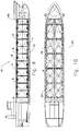
- Fig. 1 shows a typical alongside cross section of a hold for tanks in a gas carrier. Between two transverse bulkheads 5 for example four such tanks may be arranged. All support forces in this example is foreseen to be in three horizontal planes. The number of planes may be altered when desirable. In Figs. 1 and 2 , all vertical forces are supported via a suitable number of transverse webs 14. The number and the size of these webs are depending upon the size of cargo tanks 4, 40 and the structure in the bottom of the ship, possibly a double bottom construction as required today, and the main deck 6. The planes 2 and 3 are arranged to support all horizontal forces including pitching moment.
- Fig. 2 presents a typical detail from one of more vertical support elements 13 below the cargo tank 4, 40.
- the support element 13 comprises a transverse web 14, welded to the inner bottom of the bulkhead 7 aligned with the main webs of the ship and a corresponding web 16, welded to the bottom of the cargo tank. Between these two webs is installed a bottom insulation layer 15 made of hardwood or a material with similar properties.
- the webs are secured against tilting by means of support elements 13 that are aligned with double bottom stiffening ribs 12 in the bottom of the ship and the cargo tank bottom stiffener rib 17.
- the support elements just support vertical force and the bottom insulation layer 15 insulates the cargo tank 4, 40 from the structure of the ship.
- the base of this vertical tank 4, 40 is generally flat and generally flexible. Underneath this base are a number of generally evenly distributed support elements. The pressure from the contents of the tank gets evenly distributed to the support elements and further through the bottom structure of the vessel 41 and then to the water pressure on the outer bottom 10 of the vessel. In this way there are not imposed any sizable bending moment from a tank to the structure of the vessel. If the bottom had a rigid construction, this would be difficult to achieve.
- Common self supporting tanks normally have support frames covering only part of the tank e.g. in a ring underneath and covering the outer part of the base of the tank.
- a support point pair 8 is a word structure shown in Figs. 4 and 5 .
- a support point pair 8 comprises two main components, the first being a hull support pair 24 and the second being a tank support pair.
- the hull support pair 24 comprises a number of generally parallel profiles being welded or otherwise anchored to the transverse bulkhead 5 or to the hull of the ship 41. Orthogonally to these profiles are arranged two opposite surfaces of contact.
- the tank support pair 25 comprises, in a similar fashion, an number of generally parallel profiles being welded or otherwise anchored to the tank shell 23 of the cargo tank 4, 40, 104. Orthogonally to these profiles also are arranged surfaces of contact on two opposite sides.
- an insulation layer 26 is arranged with a purpose of spreading the applied forces over the two surfaces of contact.
- a corresponding insulation layer 26 is arranged between the remaining two surfaces of contact.
- the number of support point pairs 8 in the planes 2 and 3 are in the drawings minimized to 2 in each plane, but in some cases 3 or more may be more suitable.
- the least number of support points that are necessary to support horizontal movements of a vertical tank is 4, preferably separated about 90 degrees, distributed in two planes.
- the construction is preferably carried out horizontal support point pairs 8.
- Figs. 17 to 21 with details from Figs. 4 and 5 , the construction in the presented cross sections orthogonal to the presented forces that are acting. In these is to observe that the support, with positive force, is carried out in such a way that a force in one direction, e.g. from the cargo tank 4, 40, 104 and, upwards in Figs.
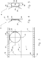
- Fig. 3 presents a horizontal cross section through a typical hold and a typical cargo tank 4, 40. Just one cargo tank 4, 40 is shown in the drawing, but the number may vary.
- Fig. 3 represents cross sections in both planes 2 and 3, these planes possibly being similar. Each plane will have at least 2 support point pairs 8, arranged with a mutual angle that is generally orthogonal, one of the support point pairs being designed to support alongside load and the other transverse load.
- FIG. 4 shows a detail of a typical support point pair 8 and Fig. 5 shows the same detail in exploded view.
- a support point pair 8 comprises a tank support pair 25, comprising a number of parallel faces, each being welded or fastened in some other way to a tank shell 23 of a cargo tank 4, 40, possibly combined with ring stiffeners on the tank, not shown.
- a compatible frame or hull support pair 24 with recess for the support 25 on the tank 4, 40 is welded to the inside of the ship side 19. The recess in the frame on the ship makes room for an insulation layer 26 made of hardwood on each side.
- the insulation layer 26 is foreseen to transfer only general pressure, orthogonally related to the faces of the insulation layer 26, so that the insulation layer 26 on the front side of a support point pair 8 receives loads that are directed forwards, while the pressure plate 26 on the back side receives the loads that are directed backwards.
- Support point pairs 8 in this preferred embodiment address only horizontal forces while all vertical forces are transferred through the construction below plane 1.
- the support point pairs 8 are designed to be as long as to accept a construction where a centre in the reaction force from the ship is generally tangential to the middle of the tank shell 23. This results in that no torque is applied into the tank shell 23, but that the force goes tangentially directly into the shell as pressure. This gives a generally even distribution of stress in the tank shell.
- the construction has enough flexibility in the insulation layers 26, 15, to transfer all forces, including forces from deformation, e.g. initiated by temperature variations and the moving of the ship 41, without undesirable stress being inflicted upon cargo tank 4, 40 or ship.
- the cargo tank may expand or shrink freely in radial directions without inflicting corresponding support point pair 8 any additional force. This is particularly important when expecting as great temperature variations as for e.g. LNG.
- Figs. 6, 7 and 8 illustrate schematically how loads are transferred to the hull.
- the total applied vertical load 29, is transferred in plane 1 by the vertical support elements shown in Fig. 2 .
- Horizontal static and dynamic loads are transferred through the support point pairs 8 in planes 2 and 3.
- a horizontal alongside load 34 applied to the tank 4, 40 will primarily be supported by the support point pair 8 at the longitudinal bulkhead.
- the reaction load 35 will in this example result in a torque 37 applied to the tank which is supported by a secondary reaction load 36 in the support point pair 8 arranged at the transverse bulkhead 5.
- Support point pair 8 in plane 3 may in such cases take on generally the whole load, and the support point pairs 8 in plane 2 will only contribute in extreme cases in which the whole of the tank is influenced to slide or move horizontally. If the support in plane 1 prevents the tank from sliding of move horizontally, one may leave out arranging the support in plane 2.
- the construction has to be designed with flexibility and tolerances to handle all loads, including loads resulting from deformations, that may be initiated e.g. by temperature variations and the movement of the vessel, without undesirable strain being enforced on to the cargo tank 4, 40 or ship 41.
- the cargo tank may in principle expand or shrink freely in its radial or axial direction without adding any additional strain to any of the support point pairs 8 or support point quads 9. This is quite important when having large temperature variations as with e.g. LNG.
- Both horizontal and vertical applied forces acting on big tanks 4, 40 should be applied as close to the tank shell 23 as possible, preferably by letting the forces act along the middle of the shell, so that bending forces do not act into the tank. This is done in the present invention through the construction in the support point pair 8 and the support point quad 9, allowing the forces act along the centre line 27 of this construction 8, 9 tangential to the centre line of the tank 4, 40.
- the length of the hull support pair 24, and tank support pair 25 may vary to a large extent depending on the shape of the tank. It may even be split in separate halves for long designs, including long horizontal tanks.
Landscapes
- Engineering & Computer Science (AREA)
- Mechanical Engineering (AREA)
- Chemical & Material Sciences (AREA)
- Combustion & Propulsion (AREA)
- Ocean & Marine Engineering (AREA)
- General Engineering & Computer Science (AREA)
- Filling Or Discharging Of Gas Storage Vessels (AREA)
- Other Liquid Machine Or Engine Such As Wave Power Use (AREA)
- Supply Devices, Intensifiers, Converters, And Telemotors (AREA)
Claims (5)
- Ladetank (4, 40), der ein Haltesystem für eine vertikale Anordnung des Ladetanks in einem Behälter (41) umfasst, wobei der Ladetank (4, 40) eine zylindrische Hülle umfasst, die eine flache und flexible Basis aufweist;
wobei der Ladetank (4,40) ferner Haltepunktpaare (8) mit an der Tankhülle (23) befestigten Tankdruckflächen (38) und entsprechende Manteldruckflächen umfasst, die mit zwischen den Tankdruckflächen (38) und den Manteldruckflächen (39) angeordnetem Isoliermaterial an dem Behälter befestigbar sind, und wobei
zwei Haltepunktpaare (8) an dem oberen Ende des Tanks (4, 40) angeordnet sind und zwei Haltepunktpaare (8) an dem unteren Ende des Tanks (4, 40) angeordnet sind; wobei:- der Ladetank (4, 40) unterhalb der Basis des Tanks gleichmäßig verteilte Halteelemente (13) umfasst, wobei jedes eine Isolierschicht (15) umfasst, wobei vertikale Kräfte von dem Tank als Druck übertragbar sind, der von den Inhalten des Tanks zu der Bodenstruktur des Behälters gleichmäßig verteilt wird;- ein Haltepunktpaar (8) an dem oberen Ende und ein Haltepunktpaar (8) an dem unteren Ende Tankdruckflächen (38) aufweist, die in dem Behälter quer anordenbar sind,- und das andere obere und untere Haltepunktpaar (8) in dem Behälter (41) längs anordenbare Tankdruckflächen (38) aufweist,- eine entsprechende Manteldruckfläche (39) nahe neben jeder der Tankdruckflächen (38) angeordnet ist und an einer inneren Schiffseite (19) oder an einem Schott (5) befestigbar ist; und wobei- die Tankdruckfläche (38) und die entsprechende Manteldruckfläche (39) derart lang und ausgerichtet hergestellt sind, dass sich eine Mittellinie, die zu der Tankdruckfläche (38) orthogonal und zu der Manteldruckfläche (39) orthogonal ist, entlang einer Linie erstreckt, die tangential zu einem Kreis ist, der mit der Tankhülle konzentrisch ist und durch die Mitte der Wand des Tanks (4, 40) verläuft, und wobei die Isolierschichten (26) zum Übertragen der Last zwischen der Tankdruckfläche (38) und der Manteldruckfläche (39) als bezüglich der Flächen der Isolationsschicht (26) orthogonaler Druck und zur selben Zeit zur thermischen Isolation zwischen dem Ladetank (4,40) und dem Behälter (41) konfiguriert sind. - Ladetank (4, 40) nach Anspruch 1, umfassend:zwischen zwei und sechs Paaren von Tankdruckflächen (38), die an der Tankhülle (23) befestigt sind, wobei in dem Behälter (41) zwischen einem und vier Paaren der Tankdruckflächen (38) quer angeordnet sind und zwischen einem und zwei Paaren der Tankdruckflächen (38) längs angeordnet sind;eine entsprechende Manteldruckfläche (39), die nahe neben jeder der Tankdruckflächen (39) anbringbar und an einer Schiffsseite (19) oder einem Schott (5) befestigbar ist, und eine Isolationsschicht (26), die zwischen den Trankdruckflächen (38) und den Manteldruckflächen (39) anordenbar ist.
- Ladetank (4, 40) nach Anspruch 2, umfassend,
sechs Paare von Tankdruckflächen (38), die an der Tankhülle (23) befestigt sind, wobei in dem Behälter (41) vier Paare der Tankdruckflächen (38) quer angeordnet sind und zwei Paare der Tankdruckflächen (38) längs angeordnet sind;
eine entsprechende Manteldruckfläche (39), die nahe neben jeder der Tankdruckflächen angeordnet und an einer Schiffsseite (19) oder einem Schott (5) befestigbar ist, und eine Isolationsschicht (26), die zwischen den Trankdruckflächen (38) und den Manteldruckflächen (39) anordenbar ist. - Behälter (41), der einen Ladetank (4, 40) nach einem der Ansprüche 1 bis 3 umfasst.
- Verwendung eines Ladetanks (4, 40) nach einem der Ansprüche 1 bis 3 zum Speichern und/oder Transportieren von Flüssigkeiten in einem Behälter (41).
Priority Applications (2)
| Application Number | Priority Date | Filing Date | Title |
|---|---|---|---|
| PL11796013T PL2583023T3 (pl) | 2010-06-18 | 2011-06-20 | Podpora zbiorników w jednostkach pływających |
| HRP20211110TT HRP20211110T1 (hr) | 2010-06-18 | 2011-06-20 | Podrška spremnicima u plovilima |
Applications Claiming Priority (3)
| Application Number | Priority Date | Filing Date | Title |
|---|---|---|---|
| NO20100881 | 2010-06-18 | ||
| NO20101555A NO336135B1 (no) | 2010-11-04 | 2010-11-04 | Opplagring av tanker i fartøy |
| PCT/NO2011/000177 WO2011159170A1 (en) | 2010-06-18 | 2011-06-20 | Support of tanks in vessels |
Publications (3)
| Publication Number | Publication Date |
|---|---|
| EP2583023A1 EP2583023A1 (de) | 2013-04-24 |
| EP2583023A4 EP2583023A4 (de) | 2017-12-27 |
| EP2583023B1 true EP2583023B1 (de) | 2021-04-14 |
Family
ID=45348386
Family Applications (1)
| Application Number | Title | Priority Date | Filing Date |
|---|---|---|---|
| EP11796013.8A Active EP2583023B1 (de) | 2010-06-18 | 2011-06-20 | Stütze für tanks in schiffen |
Country Status (10)
| Country | Link |
|---|---|
| US (1) | US9067645B2 (de) |
| EP (1) | EP2583023B1 (de) |
| JP (1) | JP6121900B2 (de) |
| KR (1) | KR101851025B1 (de) |
| CN (1) | CN102947638B (de) |
| BR (1) | BR112012032220B1 (de) |
| HR (1) | HRP20211110T1 (de) |
| PL (1) | PL2583023T3 (de) |
| SG (1) | SG186091A1 (de) |
| WO (1) | WO2011159170A1 (de) |
Families Citing this family (12)
| Publication number | Priority date | Publication date | Assignee | Title |
|---|---|---|---|---|
| BR112015025794A2 (pt) * | 2013-04-23 | 2017-07-25 | Kawasaki Heavy Ind Ltd | estrutura de sustentação de tanque de navio e carreador de gás liquefeito |
| CN105383644B (zh) * | 2014-08-19 | 2018-06-29 | 江南造船(集团)有限责任公司 | 一种独立c型液舱支承系统 |
| FR3041603B1 (fr) * | 2015-09-29 | 2018-07-13 | Gaztransport Et Technigaz | Cuve etanche et isolante disposee dans un navire |
| KR101819295B1 (ko) * | 2015-12-16 | 2018-01-17 | 주식회사 포스코 | 저장용기 지지장치 |
| SG11201803401TA (en) * | 2016-10-24 | 2019-01-30 | Chiyoda Corp | Manufacturing method of floating liquefied hydrocarbon gas plant |
| WO2018115152A1 (en) * | 2016-12-23 | 2018-06-28 | Single Buoy Moorings Inc. | Floating cryogenic hydrocarbon storage structure |
| KR20220086666A (ko) * | 2019-11-29 | 2022-06-23 | 미츠비시 조우센 가부시키가이샤 | 탱크의 지지 구조, 선박 |
| AU2021394134A1 (en) * | 2020-12-11 | 2023-07-13 | Global Hydrogen Ventures Pty Ltd | Apparatus for gas storage and transport |
| CN113602412B (zh) * | 2021-08-26 | 2024-04-12 | 中国舰船研究设计中心 | 基于钛合金的舷间压载水舱和潜水系统 |
| CN114104189B (zh) * | 2021-11-30 | 2025-06-27 | 中国船舶工业集团公司第七0八研究所 | 一种棱形独立型燃料舱的多功能支撑装置 |
| CN116573106A (zh) * | 2022-12-07 | 2023-08-11 | 大连船舶重工集团有限公司 | 一种少压载水的液化二氧化碳运输船 |
| CN115959260B (zh) * | 2022-12-15 | 2024-09-13 | 招商局金陵鼎衡船舶(扬州)有限公司 | 一种全压式lpg运输船货罐完整性吊装建造工艺 |
Citations (2)
| Publication number | Priority date | Publication date | Assignee | Title |
|---|---|---|---|---|
| JPS4831784U (de) * | 1971-08-20 | 1973-04-17 | ||
| WO2010020431A1 (de) * | 2008-08-21 | 2010-02-25 | Tge Marine Gas-Engineering Gmbh | Vorrichtung zur lagerung eines tanks für tiefkalte medien |
Family Cites Families (12)
| Publication number | Priority date | Publication date | Assignee | Title |
|---|---|---|---|---|
| FR1230091A (fr) * | 1959-06-02 | 1960-09-13 | Anciens Chantiers Dubigeon Sa | Procédés pour assurer l'installation à bord d'un navire, de réservoirs contenantdes hydrocarbures liquéfiés à basse température |
| US3583351A (en) | 1968-10-28 | 1971-06-08 | Exxon Research Engineering Co | Vessel for transporting liquefied hydrocarbon |
| US3583352A (en) * | 1968-12-24 | 1971-06-08 | Technigaz | Supporting device for self-carrying cylindrical or spherical storage tanks and its various applications |
| FR2124037A2 (en) | 1969-12-29 | 1972-09-22 | Leroux Rene | Tanker with multicullular reservoir - modified for transport at low temperature of pressurized liquefied gas |
| US4013030A (en) | 1976-02-26 | 1977-03-22 | Chicago Bridge & Iron Company | Support for LNG ship tanks |
| GB1583029A (en) | 1976-09-08 | 1981-01-21 | Martacto Naviera Sa | Tanks for the storage and transport of fluid media under pressure |
| JP2506609Y2 (ja) * | 1990-09-25 | 1996-08-14 | 石川島播磨重工業株式会社 | 液体運搬船用ガスタンクの支持装置 |
| WO2005093315A1 (en) | 2004-03-05 | 2005-10-06 | New York Bulk Carriers Inc. | Support assemblies and systems for semi-membrane tanks |
| CN100390459C (zh) * | 2006-09-07 | 2008-05-28 | 国营武昌造船厂 | 船用水垫式半浮动贮罐支承装置 |
| GB0703693D0 (en) * | 2007-02-26 | 2007-04-04 | Jahre Group As | Support structure |
| CN101737623A (zh) * | 2008-11-17 | 2010-06-16 | 张家港韩中深冷科技有限公司 | 低温贮罐中内容器的支撑装置 |
| NO20090735A (no) | 2009-02-16 | 2010-06-14 | Inocean As | Uavhengig lagringstank for lagring av flytende gass |
-
2011
- 2011-06-20 PL PL11796013T patent/PL2583023T3/pl unknown
- 2011-06-20 EP EP11796013.8A patent/EP2583023B1/de active Active
- 2011-06-20 CN CN201180030043.9A patent/CN102947638B/zh active Active
- 2011-06-20 KR KR1020127033550A patent/KR101851025B1/ko active Active
- 2011-06-20 BR BR112012032220-6A patent/BR112012032220B1/pt not_active IP Right Cessation
- 2011-06-20 SG SG2012087623A patent/SG186091A1/en unknown
- 2011-06-20 HR HRP20211110TT patent/HRP20211110T1/hr unknown
- 2011-06-20 WO PCT/NO2011/000177 patent/WO2011159170A1/en not_active Ceased
- 2011-06-20 JP JP2013515291A patent/JP6121900B2/ja active Active
-
2012
- 2012-12-05 US US13/705,612 patent/US9067645B2/en active Active
Patent Citations (2)
| Publication number | Priority date | Publication date | Assignee | Title |
|---|---|---|---|---|
| JPS4831784U (de) * | 1971-08-20 | 1973-04-17 | ||
| WO2010020431A1 (de) * | 2008-08-21 | 2010-02-25 | Tge Marine Gas-Engineering Gmbh | Vorrichtung zur lagerung eines tanks für tiefkalte medien |
Also Published As
| Publication number | Publication date |
|---|---|
| JP6121900B2 (ja) | 2017-04-26 |
| KR20130087404A (ko) | 2013-08-06 |
| US9067645B2 (en) | 2015-06-30 |
| HRP20211110T1 (hr) | 2021-10-29 |
| EP2583023A4 (de) | 2017-12-27 |
| BR112012032220A2 (pt) | 2016-11-29 |
| BR112012032220B1 (pt) | 2020-11-03 |
| KR101851025B1 (ko) | 2018-04-20 |
| US20130092073A1 (en) | 2013-04-18 |
| SG186091A1 (en) | 2013-01-30 |
| WO2011159170A1 (en) | 2011-12-22 |
| JP2013530080A (ja) | 2013-07-25 |
| EP2583023A1 (de) | 2013-04-24 |
| CN102947638B (zh) | 2015-04-01 |
| CN102947638A (zh) | 2013-02-27 |
| PL2583023T3 (pl) | 2021-10-11 |
Similar Documents
| Publication | Publication Date | Title |
|---|---|---|
| US9067645B2 (en) | Support of tanks in vessels | |
| US4182254A (en) | Tanks for the storage and transport of fluid media under pressure | |
| EP2157013B1 (de) | Flüssiggasspeichertank und Schiff, das diesen Tank enthält | |
| EP0925221B1 (de) | Tank und behältersystem für flüssiges erdgas | |
| EP2035742B1 (de) | Anordnung für einen zylindrischen tank zum transport von verflüssigten gasen bei niedriger temperatur in einem schiff | |
| CN101687534B (zh) | 支撑结构 | |
| ES2763430T3 (es) | Estructura de soporte de un depósito de carga, estructura flotante y método de soporte de un depósito de carga | |
| US6786166B1 (en) | Liquefied gas storage barge with concrete floating structure | |
| AU2014251665B2 (en) | LNG ship or LPG ship | |
| US8091494B2 (en) | Liquefied gas tank with a central hub in the bottom structure | |
| CN101932867B (zh) | 底部结构中具有中心毂的液化气体罐 | |
| KR20110105464A (ko) | 복합형 엘엔지 독립 탱크 | |
| AU2008332002B2 (en) | A liquefied gas tank with a central hub in the bottom structure | |
| EP2985218B1 (de) | Lng-tanker oder lpg-tanker | |
| KR100918199B1 (ko) | Lng 저장탱크 및 상기 lng 저장탱크를 가지는 부유식 해상구조물 | |
| KR101599294B1 (ko) | 저장탱크의 선적 및 하역장치, 그리고 상기 선적 및 하역장치를 가지는 부유식 구조물 | |
| KR101498243B1 (ko) | 부유식 해상구조물 | |
| CN120697897A (zh) | 一种纤维复合材料c型货罐二氧化碳运输船 |
Legal Events
| Date | Code | Title | Description |
|---|---|---|---|
| PUAI | Public reference made under article 153(3) epc to a published international application that has entered the european phase |
Free format text: ORIGINAL CODE: 0009012 |
|
| 17P | Request for examination filed |
Effective date: 20121127 |
|
| AK | Designated contracting states |
Kind code of ref document: A1 Designated state(s): AL AT BE BG CH CY CZ DE DK EE ES FI FR GB GR HR HU IE IS IT LI LT LU LV MC MK MT NL NO PL PT RO RS SE SI SK SM TR |
|
| RIN1 | Information on inventor provided before grant (corrected) |
Inventor name: REINES, ARNT HALVAR Inventor name: JACOBSEN, JACOB, IVAR |
|
| RIN1 | Information on inventor provided before grant (corrected) |
Inventor name: REINES, ARNT HALVAR Inventor name: JACOBSEN, JACOB, IVAR |
|
| DAX | Request for extension of the european patent (deleted) | ||
| STAA | Information on the status of an ep patent application or granted ep patent |
Free format text: STATUS: EXAMINATION IS IN PROGRESS |
|
| RA4 | Supplementary search report drawn up and despatched (corrected) |
Effective date: 20171128 |
|
| RIC1 | Information provided on ipc code assigned before grant |
Ipc: B63B 25/16 20060101ALI20171122BHEP Ipc: F17C 13/08 20060101AFI20171122BHEP |
|
| 17Q | First examination report despatched |
Effective date: 20171211 |
|
| GRAP | Despatch of communication of intention to grant a patent |
Free format text: ORIGINAL CODE: EPIDOSNIGR1 |
|
| STAA | Information on the status of an ep patent application or granted ep patent |
Free format text: STATUS: GRANT OF PATENT IS INTENDED |
|
| INTG | Intention to grant announced |
Effective date: 20201218 |
|
| GRAS | Grant fee paid |
Free format text: ORIGINAL CODE: EPIDOSNIGR3 |
|
| GRAA | (expected) grant |
Free format text: ORIGINAL CODE: 0009210 |
|
| STAA | Information on the status of an ep patent application or granted ep patent |
Free format text: STATUS: THE PATENT HAS BEEN GRANTED |
|
| AK | Designated contracting states |
Kind code of ref document: B1 Designated state(s): AL AT BE BG CH CY CZ DE DK EE ES FI FR GB GR HR HU IE IS IT LI LT LU LV MC MK MT NL NO PL PT RO RS SE SI SK SM TR |
|
| REG | Reference to a national code |
Ref country code: GB Ref legal event code: FG4D |
|
| RIN1 | Information on inventor provided before grant (corrected) |
Inventor name: REINES, ARNT HALVAR Inventor name: JACOBSEN, JACOB, IVAR |
|
| REG | Reference to a national code |
Ref country code: CH Ref legal event code: EP |
|
| REG | Reference to a national code |
Ref country code: DE Ref legal event code: R096 Ref document number: 602011070695 Country of ref document: DE |
|
| REG | Reference to a national code |
Ref country code: IE Ref legal event code: FG4D |
|
| REG | Reference to a national code |
Ref country code: AT Ref legal event code: REF Ref document number: 1382710 Country of ref document: AT Kind code of ref document: T Effective date: 20210515 |
|
| REG | Reference to a national code |
Ref country code: NL Ref legal event code: FP |
|
| REG | Reference to a national code |
Ref country code: RO Ref legal event code: EPE |
|
| REG | Reference to a national code |
Ref country code: HR Ref legal event code: TUEP Ref document number: P20211110T Country of ref document: HR |
|
| REG | Reference to a national code |
Ref country code: FI Ref legal event code: FGE |
|
| REG | Reference to a national code |
Ref country code: LT Ref legal event code: MG9D |
|
| REG | Reference to a national code |
Ref country code: AT Ref legal event code: MK05 Ref document number: 1382710 Country of ref document: AT Kind code of ref document: T Effective date: 20210414 |
|
| REG | Reference to a national code |
Ref country code: HR Ref legal event code: ODRP Ref document number: P20211110T Country of ref document: HR Payment date: 20210712 Year of fee payment: 11 |
|
| PG25 | Lapsed in a contracting state [announced via postgrant information from national office to epo] |
Ref country code: AT Free format text: LAPSE BECAUSE OF FAILURE TO SUBMIT A TRANSLATION OF THE DESCRIPTION OR TO PAY THE FEE WITHIN THE PRESCRIBED TIME-LIMIT Effective date: 20210414 Ref country code: BG Free format text: LAPSE BECAUSE OF FAILURE TO SUBMIT A TRANSLATION OF THE DESCRIPTION OR TO PAY THE FEE WITHIN THE PRESCRIBED TIME-LIMIT Effective date: 20210714 Ref country code: LT Free format text: LAPSE BECAUSE OF FAILURE TO SUBMIT A TRANSLATION OF THE DESCRIPTION OR TO PAY THE FEE WITHIN THE PRESCRIBED TIME-LIMIT Effective date: 20210414 |
|
| REG | Reference to a national code |
Ref country code: HR Ref legal event code: T1PR Ref document number: P20211110 Country of ref document: HR |
|
| PG25 | Lapsed in a contracting state [announced via postgrant information from national office to epo] |
Ref country code: IS Free format text: LAPSE BECAUSE OF FAILURE TO SUBMIT A TRANSLATION OF THE DESCRIPTION OR TO PAY THE FEE WITHIN THE PRESCRIBED TIME-LIMIT Effective date: 20210814 Ref country code: LV Free format text: LAPSE BECAUSE OF FAILURE TO SUBMIT A TRANSLATION OF THE DESCRIPTION OR TO PAY THE FEE WITHIN THE PRESCRIBED TIME-LIMIT Effective date: 20210414 Ref country code: GR Free format text: LAPSE BECAUSE OF FAILURE TO SUBMIT A TRANSLATION OF THE DESCRIPTION OR TO PAY THE FEE WITHIN THE PRESCRIBED TIME-LIMIT Effective date: 20210715 Ref country code: SE Free format text: LAPSE BECAUSE OF FAILURE TO SUBMIT A TRANSLATION OF THE DESCRIPTION OR TO PAY THE FEE WITHIN THE PRESCRIBED TIME-LIMIT Effective date: 20210414 Ref country code: RS Free format text: LAPSE BECAUSE OF FAILURE TO SUBMIT A TRANSLATION OF THE DESCRIPTION OR TO PAY THE FEE WITHIN THE PRESCRIBED TIME-LIMIT Effective date: 20210414 Ref country code: ES Free format text: LAPSE BECAUSE OF FAILURE TO SUBMIT A TRANSLATION OF THE DESCRIPTION OR TO PAY THE FEE WITHIN THE PRESCRIBED TIME-LIMIT Effective date: 20210414 Ref country code: PT Free format text: LAPSE BECAUSE OF FAILURE TO SUBMIT A TRANSLATION OF THE DESCRIPTION OR TO PAY THE FEE WITHIN THE PRESCRIBED TIME-LIMIT Effective date: 20210816 Ref country code: NO Free format text: LAPSE BECAUSE OF FAILURE TO SUBMIT A TRANSLATION OF THE DESCRIPTION OR TO PAY THE FEE WITHIN THE PRESCRIBED TIME-LIMIT Effective date: 20210714 |
|
| REG | Reference to a national code |
Ref country code: DE Ref legal event code: R097 Ref document number: 602011070695 Country of ref document: DE |
|
| PG25 | Lapsed in a contracting state [announced via postgrant information from national office to epo] |
Ref country code: MC Free format text: LAPSE BECAUSE OF FAILURE TO SUBMIT A TRANSLATION OF THE DESCRIPTION OR TO PAY THE FEE WITHIN THE PRESCRIBED TIME-LIMIT Effective date: 20210414 Ref country code: EE Free format text: LAPSE BECAUSE OF FAILURE TO SUBMIT A TRANSLATION OF THE DESCRIPTION OR TO PAY THE FEE WITHIN THE PRESCRIBED TIME-LIMIT Effective date: 20210414 Ref country code: DK Free format text: LAPSE BECAUSE OF FAILURE TO SUBMIT A TRANSLATION OF THE DESCRIPTION OR TO PAY THE FEE WITHIN THE PRESCRIBED TIME-LIMIT Effective date: 20210414 Ref country code: CZ Free format text: LAPSE BECAUSE OF FAILURE TO SUBMIT A TRANSLATION OF THE DESCRIPTION OR TO PAY THE FEE WITHIN THE PRESCRIBED TIME-LIMIT Effective date: 20210414 Ref country code: SK Free format text: LAPSE BECAUSE OF FAILURE TO SUBMIT A TRANSLATION OF THE DESCRIPTION OR TO PAY THE FEE WITHIN THE PRESCRIBED TIME-LIMIT Effective date: 20210414 Ref country code: SM Free format text: LAPSE BECAUSE OF FAILURE TO SUBMIT A TRANSLATION OF THE DESCRIPTION OR TO PAY THE FEE WITHIN THE PRESCRIBED TIME-LIMIT Effective date: 20210414 |
|
| REG | Reference to a national code |
Ref country code: CH Ref legal event code: PL |
|
| PLBE | No opposition filed within time limit |
Free format text: ORIGINAL CODE: 0009261 |
|
| STAA | Information on the status of an ep patent application or granted ep patent |
Free format text: STATUS: NO OPPOSITION FILED WITHIN TIME LIMIT |
|
| 26N | No opposition filed |
Effective date: 20220117 |
|
| PG25 | Lapsed in a contracting state [announced via postgrant information from national office to epo] |
Ref country code: LU Free format text: LAPSE BECAUSE OF NON-PAYMENT OF DUE FEES Effective date: 20210620 |
|
| PG25 | Lapsed in a contracting state [announced via postgrant information from national office to epo] |
Ref country code: LI Free format text: LAPSE BECAUSE OF NON-PAYMENT OF DUE FEES Effective date: 20210630 Ref country code: IE Free format text: LAPSE BECAUSE OF NON-PAYMENT OF DUE FEES Effective date: 20210620 Ref country code: CH Free format text: LAPSE BECAUSE OF NON-PAYMENT OF DUE FEES Effective date: 20210630 |
|
| PG25 | Lapsed in a contracting state [announced via postgrant information from national office to epo] |
Ref country code: IS Free format text: LAPSE BECAUSE OF FAILURE TO SUBMIT A TRANSLATION OF THE DESCRIPTION OR TO PAY THE FEE WITHIN THE PRESCRIBED TIME-LIMIT Effective date: 20210814 Ref country code: AL Free format text: LAPSE BECAUSE OF FAILURE TO SUBMIT A TRANSLATION OF THE DESCRIPTION OR TO PAY THE FEE WITHIN THE PRESCRIBED TIME-LIMIT Effective date: 20210414 |
|
| REG | Reference to a national code |
Ref country code: HR Ref legal event code: ODRP Ref document number: P20211110 Country of ref document: HR Payment date: 20220615 Year of fee payment: 12 |
|
| PG25 | Lapsed in a contracting state [announced via postgrant information from national office to epo] |
Ref country code: HU Free format text: LAPSE BECAUSE OF FAILURE TO SUBMIT A TRANSLATION OF THE DESCRIPTION OR TO PAY THE FEE WITHIN THE PRESCRIBED TIME-LIMIT; INVALID AB INITIO Effective date: 20110620 Ref country code: CY Free format text: LAPSE BECAUSE OF FAILURE TO SUBMIT A TRANSLATION OF THE DESCRIPTION OR TO PAY THE FEE WITHIN THE PRESCRIBED TIME-LIMIT Effective date: 20210414 |
|
| REG | Reference to a national code |
Ref country code: HR Ref legal event code: ODRP Ref document number: P20211110 Country of ref document: HR Payment date: 20230614 Year of fee payment: 13 |
|
| PGFP | Annual fee paid to national office [announced via postgrant information from national office to epo] |
Ref country code: IT Payment date: 20230523 Year of fee payment: 13 Ref country code: FR Payment date: 20230523 Year of fee payment: 13 Ref country code: DE Payment date: 20230523 Year of fee payment: 13 |
|
| PGFP | Annual fee paid to national office [announced via postgrant information from national office to epo] |
Ref country code: FI Payment date: 20230523 Year of fee payment: 13 |
|
| PGFP | Annual fee paid to national office [announced via postgrant information from national office to epo] |
Ref country code: BE Payment date: 20230523 Year of fee payment: 13 |
|
| PG25 | Lapsed in a contracting state [announced via postgrant information from national office to epo] |
Ref country code: MK Free format text: LAPSE BECAUSE OF FAILURE TO SUBMIT A TRANSLATION OF THE DESCRIPTION OR TO PAY THE FEE WITHIN THE PRESCRIBED TIME-LIMIT Effective date: 20210414 |
|
| REG | Reference to a national code |
Ref country code: HR Ref legal event code: ODRP Ref document number: P20211110 Country of ref document: HR Payment date: 20240527 Year of fee payment: 14 |
|
| PGFP | Annual fee paid to national office [announced via postgrant information from national office to epo] |
Ref country code: GB Payment date: 20240628 Year of fee payment: 14 |
|
| PGFP | Annual fee paid to national office [announced via postgrant information from national office to epo] |
Ref country code: HR Payment date: 20240527 Year of fee payment: 14 Ref country code: NL Payment date: 20240607 Year of fee payment: 14 |
|
| PGFP | Annual fee paid to national office [announced via postgrant information from national office to epo] |
Ref country code: RO Payment date: 20240618 Year of fee payment: 14 |
|
| PGFP | Annual fee paid to national office [announced via postgrant information from national office to epo] |
Ref country code: PL Payment date: 20240523 Year of fee payment: 14 |
|
| PGFP | Annual fee paid to national office [announced via postgrant information from national office to epo] |
Ref country code: TR Payment date: 20240522 Year of fee payment: 14 |
|
| PG25 | Lapsed in a contracting state [announced via postgrant information from national office to epo] |
Ref country code: MT Free format text: LAPSE BECAUSE OF FAILURE TO SUBMIT A TRANSLATION OF THE DESCRIPTION OR TO PAY THE FEE WITHIN THE PRESCRIBED TIME-LIMIT Effective date: 20210414 |
|
| REG | Reference to a national code |
Ref country code: DE Ref legal event code: R119 Ref document number: 602011070695 Country of ref document: DE |
|
| PG25 | Lapsed in a contracting state [announced via postgrant information from national office to epo] |
Ref country code: FI Free format text: LAPSE BECAUSE OF NON-PAYMENT OF DUE FEES Effective date: 20240620 |
|
| PG25 | Lapsed in a contracting state [announced via postgrant information from national office to epo] |
Ref country code: FI Free format text: LAPSE BECAUSE OF NON-PAYMENT OF DUE FEES Effective date: 20240620 |
|
| PG25 | Lapsed in a contracting state [announced via postgrant information from national office to epo] |
Ref country code: DE Free format text: LAPSE BECAUSE OF NON-PAYMENT OF DUE FEES Effective date: 20250101 |
|
| PG25 | Lapsed in a contracting state [announced via postgrant information from national office to epo] |
Ref country code: BE Free format text: LAPSE BECAUSE OF NON-PAYMENT OF DUE FEES Effective date: 20240630 |
|
| PG25 | Lapsed in a contracting state [announced via postgrant information from national office to epo] |
Ref country code: FR Free format text: LAPSE BECAUSE OF NON-PAYMENT OF DUE FEES Effective date: 20240630 |
|
| PG25 | Lapsed in a contracting state [announced via postgrant information from national office to epo] |
Ref country code: IT Free format text: LAPSE BECAUSE OF NON-PAYMENT OF DUE FEES Effective date: 20240620 |
|
| REG | Reference to a national code |
Ref country code: BE Ref legal event code: MM Effective date: 20240630 |
|
| REG | Reference to a national code |
Ref country code: HR Ref legal event code: PBON Ref document number: P20211110 Country of ref document: HR Effective date: 20250620 |
|
| PG25 | Lapsed in a contracting state [announced via postgrant information from national office to epo] |
Ref country code: RO Free format text: LAPSE BECAUSE OF NON-PAYMENT OF DUE FEES Effective date: 20250620 |
|
| REG | Reference to a national code |
Ref country code: NL Ref legal event code: MM Effective date: 20250701 |
|
| GBPC | Gb: european patent ceased through non-payment of renewal fee |
Effective date: 20250620 |
|
| PG25 | Lapsed in a contracting state [announced via postgrant information from national office to epo] |
Ref country code: NL Free format text: LAPSE BECAUSE OF NON-PAYMENT OF DUE FEES Effective date: 20250701 |
|
| PG25 | Lapsed in a contracting state [announced via postgrant information from national office to epo] |
Ref country code: GB Free format text: LAPSE BECAUSE OF NON-PAYMENT OF DUE FEES Effective date: 20250620 |
|
| PG25 | Lapsed in a contracting state [announced via postgrant information from national office to epo] |
Ref country code: HR Free format text: LAPSE BECAUSE OF NON-PAYMENT OF DUE FEES Effective date: 20250620 |