EP2036580B1 - Appareil de Stérilisation - Google Patents
Appareil de Stérilisation Download PDFInfo
- Publication number
- EP2036580B1 EP2036580B1 EP08020908.3A EP08020908A EP2036580B1 EP 2036580 B1 EP2036580 B1 EP 2036580B1 EP 08020908 A EP08020908 A EP 08020908A EP 2036580 B1 EP2036580 B1 EP 2036580B1
- Authority
- EP
- European Patent Office
- Prior art keywords
- electrode
- needle
- ceramic plate
- air
- shaped electrode
- Prior art date
- Legal status (The legal status is an assumption and is not a legal conclusion. Google has not performed a legal analysis and makes no representation as to the accuracy of the status listed.)
- Expired - Lifetime
Links
Images




Classifications
-
- A—HUMAN NECESSITIES
- A61—MEDICAL OR VETERINARY SCIENCE; HYGIENE
- A61L—METHODS OR APPARATUS FOR STERILISING MATERIALS OR OBJECTS IN GENERAL; DISINFECTION, STERILISATION OR DEODORISATION OF AIR; CHEMICAL ASPECTS OF BANDAGES, DRESSINGS, ABSORBENT PADS OR SURGICAL ARTICLES; MATERIALS FOR BANDAGES, DRESSINGS, ABSORBENT PADS OR SURGICAL ARTICLES
- A61L9/00—Disinfection, sterilisation or deodorisation of air
- A61L9/16—Disinfection, sterilisation or deodorisation of air using physical phenomena
- A61L9/22—Ionisation
-
- B—PERFORMING OPERATIONS; TRANSPORTING
- B03—SEPARATION OF SOLID MATERIALS USING LIQUIDS OR USING PNEUMATIC TABLES OR JIGS; MAGNETIC OR ELECTROSTATIC SEPARATION OF SOLID MATERIALS FROM SOLID MATERIALS OR FLUIDS; SEPARATION BY HIGH-VOLTAGE ELECTRIC FIELDS
- B03C—MAGNETIC OR ELECTROSTATIC SEPARATION OF SOLID MATERIALS FROM SOLID MATERIALS OR FLUIDS; SEPARATION BY HIGH-VOLTAGE ELECTRIC FIELDS
- B03C3/00—Separating dispersed particles from gases or vapour, e.g. air, by electrostatic effect
- B03C3/34—Constructional details or accessories or operation thereof
- B03C3/38—Particle charging or ionising stations, e.g. using electric discharge, radioactive radiation or flames
-
- F—MECHANICAL ENGINEERING; LIGHTING; HEATING; WEAPONS; BLASTING
- F24—HEATING; RANGES; VENTILATING
- F24F—AIR-CONDITIONING; AIR-HUMIDIFICATION; VENTILATION; USE OF AIR CURRENTS FOR SCREENING
- F24F8/00—Treatment, e.g. purification, of air supplied to human living or working spaces otherwise than by heating, cooling, humidifying or drying
- F24F8/20—Treatment, e.g. purification, of air supplied to human living or working spaces otherwise than by heating, cooling, humidifying or drying by sterilisation
-
- F—MECHANICAL ENGINEERING; LIGHTING; HEATING; WEAPONS; BLASTING
- F24—HEATING; RANGES; VENTILATING
- F24F—AIR-CONDITIONING; AIR-HUMIDIFICATION; VENTILATION; USE OF AIR CURRENTS FOR SCREENING
- F24F8/00—Treatment, e.g. purification, of air supplied to human living or working spaces otherwise than by heating, cooling, humidifying or drying
- F24F8/30—Treatment, e.g. purification, of air supplied to human living or working spaces otherwise than by heating, cooling, humidifying or drying by ionisation
-
- H—ELECTRICITY
- H01—ELECTRIC ELEMENTS
- H01T—SPARK GAPS; OVERVOLTAGE ARRESTERS USING SPARK GAPS; SPARKING PLUGS; CORONA DEVICES; GENERATING IONS TO BE INTRODUCED INTO NON-ENCLOSED GASES
- H01T23/00—Apparatus for generating ions to be introduced into non-enclosed gases, e.g. into the atmosphere
Definitions
- the present invention relates to a sterilizing apparatus for killing bacteria by generating ions.
- an air cleaning apparatus includes a filter mounted in a housing for filtering diverse impurities; a blowing fan for introducing air from a room space into the housing, thereby forcing the introduced air to pass through the filter, and for discharging the filtered air out of the housing; and an anion generator for generating anions.
- JP 2004-138268 refers to emitting electrons in a straight line from a needle electrode generated by corona discharge, and distantly delivering a generated ionic wind.
- EP 1 625 890 A2 discloses an ion generating element and an ion generating apparatus that, by releasing positive and negative ions into a space, can decompose bacteria, mold spores, toxic substances, and the like floating in the air.
- EP 1 791 232 A1 which was published after the application date of the present invention discloses an ion generating apparatus and an air cleaning apparatus using the same, and, more particularly, an ion generating apparatus for generating anions and cations, and an air cleaning apparatus using the same.
- the room air is cleaned while passing through the filter when the blowing fan is driven, and is then discharged into the room space, together with anions generated from the anion generator.
- a conventional air cleaning apparatus which includes a filter and an anion generator, is limited in its ability to kill bacteria floating in the air, using only the filter and anions generated from the anion generator.
- a new ion generator has been proposed which performs sterilization using both anions and cations. Such an ion generator, which can generate both anions and cations, is described in Japanese Patent Laid-open Publication No. 2003-123940 .
- this conventional ion generator has a problem in that the hydrogen ions, which are harmful to the human body, are discharged into the room space intact, so that the user's health may be negatively impacted upon inhaling the hydrogen ions.
- each electrode since each electrode alternately generates anions and cations, considerable amounts of anions and cations are coupled before they can be used for sterilization, so that their effectiveness is lost.
- each electrode since each electrode alternately generates anions and cations, it is impossible to generate sufficient amounts of anions and cations required for sterilization within a short period of time.
- the invention provides a sterilizing apparatus according to claim 1.
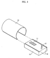
- FIGS. 1 and 2 illustrate a sterilizing apparatus .
- the sterilizing apparatus includes a base 10, a ceramic plate 11 mounted on an upper surface of the base 10, a needle-shaped electrode 12 mounted on the base 10 while being spaced apart from the ceramic plate 11 by a predetermined distance, and a cover 13 which defines the diffusion range of ions generated from the ceramic plate 11 and needle-shaped electrode 12 within a predetermined space.
- a recess is provided at the upper surface of the base 10 for mounting the ceramic plate 11.
- the ceramic plate 11 is fitted in the base 10.
- the ceramic plate 11 is adapted for generating cations.
- a discharge electrode 14 is provided at an upper surface of the ceramic plate 11 inside the ceramic plate 11.
- An induction electrode 15 is also provided at a middle portion within the ceramic plate 11 when viewed in a thickness direction of the ceramic plate 11. The remaining portion of the ceramic plate 11 is made of ceramic to form a protective layer.
- a high positive voltage is applied between the discharge electrode 14 and the induction electrode 15.
- the high positive voltage is preferably 3.9kV to 4.3kV, even though it may have other voltage ranges.
- plasma discharge occurs at the ceramic plate 11, so that moisture (H 2 O) present in the air around the ceramic plate 11 is ionized, thereby generating hydrogen ions (H + ).
- a high negative voltage is applied between the needle-shaped electrode 12 and a ground electrode 17.
- the high negative voltage is preferably - 3.2kV to -3.6kV, even through it may have other voltage ranges.
- plasma discharge occurs at the needle-shaped electrode 12, so that cations are accumulated around the needle-shaped electrode 12, and a large amount of electrons are discharged from the needle-shaped electrode 12 into the air.
- the electrons discharged into the air are very unstable and therefore are captured by oxygen molecules (O 2 ) in the air, thereby forming super-oxide anions (O 2 - ).
- O 2 oxygen molecules
- O 2 - super-oxide anions
- Electrons discharged from the needle-shaped electrode 12 are coupled with hydrogen ions reaching the needle-shaped electrode 12 after being generated from the ceramic plate 11, so that hydrogen atoms (or active hydrogen) are produced.
- a blower 18 may be arranged at one side of the sterilizing apparatus to forcibly feed the hydrogen ions toward the needle-shaped electrode 12.
- the needle-shaped electrode 12 is spaced apart from the ceramic plate 11 by a predetermined distance. It is desirable to appropriately determine the spacing between the ceramic plate 11 and the needle-spaced electrode 12, based on the size of the ceramic plate 11 and the height of the needle-shaped electrode 12. This is because the amount of hydrogen atoms formed from the hydrogen ions generated from the ceramic plate 11 varies depending on the spacing between the ceramic plate 11 and the needle-shaped electrode 12.
- the cover 13 has a tunnel-shaped structure opened at the bottom thereof to have a pair of laterally-spaced longitudinal lower ends.
- the cover 13 is separably coupled with the base 10 in such a manner that the lower ends of the cover 13 are slidably engaged with cover rails 16 formed at lateral ends of the base 10 on the upper surface of the base 10, respectively.
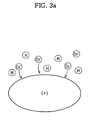
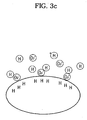
- FIGS. 3a to 3e a sterilizing method carried out by the sterilizing apparatus of FIG. 1 will be described with reference to FIGS. 3a to 3e .
- a high positive voltage is first applied between the discharge electrode 14 and induction electrode 15 in the ceramic plate 11, thereby generating hydrogen ions.
- a high negative voltage is applied to the needle-shaped electrode 12, thereby generating electrons and super-oxide anions.
- air is blown into the cover 13 at one side of the cover 13 to feed the hydrogen ions to the needle-shaped electrode 12 or a region around the needle-shaped electrode 12.
- the super-oxide anions which are discharged from the sterilizing apparatus into the air, exhibit a polarity opposite to static electricity (+) of bacteria floating in the air, so that the super-oxide anions are adsorbed to the surface of the bacteria, as shown in FIG. 3a .
- the hydrogen atoms which are discharged from the sterilizing apparatus into the air, react with the super-oxide anions, as shown in FIGS. 3b and 3c .
- the super-oxide anions and hydrogen atoms which react with each other, form hydroperoxy radicals.
- the electrons of the super-oxide anions offset the static electricity of the bacteria.
- Each hydroperoxy radical then captures three hydrogen atoms from the protein forming the cell membrane of the bacteria, thereby producing two water molecules.
- the protein molecules of the cell membrane which donate the hydrogen atoms, are destroyed, thereby causing the cell membrane of the bacteria to be destroyed.
- sterilization is achieved.
- the testing apparatus includes a chamber 30, a virus supplier 31 arranged at one side wall of the chamber 30, an ambient air sucking filter 32 arranged at one side wall of the chamber 30 beneath the virus supplier 31, and a discharge duct 33 connected to the other side wall of the chamber 30.
- a detection filter 34 is arranged in the discharge duct 33.
- a suction pump 35 is mounted to an outlet end of the discharge duct 33.
- a table 36, on which the sterilizing apparatus is to be laid for testing thereof, is arranged in the chamber 30.
- a blowing fan 37 is also arranged in the chamber 30 to blow air to the sterilizing apparatus.
- the sterilizing apparatus is first laid on the table 36 in the testing apparatus. Thereafter, viruses (Influenza viruses, New Caledonia) are supplied from the virus supplier 31 into the chamber 30 for 10 minutes. After completion of the virus supply from the virus supplier 31, the sterilizing apparatus and blowing fan 37 are driven for 30 minutes. Subsequently, the suction pump 35 is driven. In this state, the number of viruses detected by the detection filter 34 is checked.
- FIG. 5 shows graphs respectively depicting the number of supplied viruses and the number of viruses detected by the detection filter 34.
- the Y-axis represents the number of viruses (log scale)
- the graph A represents the number of viruses supplied from the virus supplier 31
- the graph B represents the number of viruses detected after 30 minutes without driving the sterilizing apparatus
- the graph C represents the number of viruses detected after 30 minutes of driving the sterilizing apparatus.
- FIGS. 6 and 7 a sterilizing apparatus according to an embodiment of the present invention is illustrated.
- constituent elements respectively corresponding to those in FIGS. 1 and 2 are denoted by the same reference numerals. As shown in FIGS.
- the sterilizing apparatus includes a base 10, a ceramic plate 11 mounted on an upper surface of the base 10, a first needle-shaped electrode 19 mounted on the base 10 while being spaced apart from the ceramic plate 11 by a desired distance to generate electrons, a second needle-shaped electrode 21 mounted on the base 10 while being spaced apart from the first needle-shaped electrode 19 by a desired distance to generate super-oxide anions, and a cover 13 to define the diffusion range of ions generated from the ceramic plate 11 and needle-shaped electrodes 19 and 21 within a predetermined space.
- the ceramic plate 11 and cover 13 of FIG. 6 are the same as those of FIGS. 1 and 2 , so that no description thereof will be given.
- a high negative voltage is applied between the first needle-shaped electrode 19 and the ground electrode 17
- plasma discharge occurs at the first needle-shaped electrode 19, so that cations accumulate around the first needle-shaped electrode 19, and a large amount of electrons are discharged from the first needle-shaped electrode 19 into the air.
- the first needle-shaped electrode 19 Since the first needle-shaped electrode 19 is arranged in the vicinity of the ceramic plate 11, the electrons discharged from the first needle-shaped electrode 19 are coupled with hydrogen ions reaching the first needle-shaped electrode 19 after being generated from the ceramic plate 11, so that hydrogen atoms (or active hydrogen) are produced.
- a blower 18 may be arranged at one side of the sterilizing apparatus to forcibly feed the hydrogen ions toward the first needle-shaped electrode 19.
- the hydrogen ions discharged from the ceramic plate 11 are coupled with the electrons generated from the first needle-shaped electrode 19, thereby producing hydrogen atoms.
- the hydrogen atoms react with the super-oxide anions generated from the second needle-shaped electrode 21, thereby producing hydroperoxy radicals having a sterilizing function.
- hydrogen atoms are produced, using electrons generated from the first needle-shaped electrode 19, and super-oxide anions are generated from the second needle-shaped electrode 21, as compared to the first embodiment.
- the first and second needle-shaped electrodes 19 and 21 are spaced apart from the ceramic plate 11 by predetermined distances, respectively. It is desirable to appropriately determine the spacing between the ceramic plate 11 and each needle-spaced electrode, based on the size of the ceramic plate 11 and the height of the needle-shaped electrode, to achieve maximal hydrogen atom producing performance.
- the embodiment of the present invention has been described in terms of a method in which a high negative voltage is applied to both the first and second needle-shaped electrodes 19 and 21, the high negative voltage may be applied to the first needle-shaped electrode 19 alone.
- hydrogen atoms, which are generated from the first needle-shaped electrode 19 are coupled with super-oxide anions, which are a kind of active oxygen naturally generated in the air, thereby removing the super-oxide anions.
- the air cleaning apparatus includes a body 40, an inlet 41 arranged at one side wall of the body 40, an outlet 42 arranged at the other side wall of the body 40, a filter 43 mounted in the body 40, a blower 44 to forcibly circulate room air such that the room air is discharged out of the body 40 after passing through the filter 43, and the sterilizing apparatus of FIG. 1 arranged in an air discharge path 45 defined in the body 40.
- the blower 44 When the blower 44 is driven to clean the room air in the air cleaning apparatus, the room air is sucked into the interior of the body 40 through the inlet 41, and then passes through the filter 43, so that impurities are removed from the room air by the filter 43. Thereafter, the room air is fed along the air discharge path 45 to be discharged out of the body 40 through the outlet 42.
- the sterilizing apparatus may be driven, simultaneously with the driving of the blower 44.
- hydrogen atoms and super-oxide anions are discharged into the air discharge path 45. Accordingly, bacteria present in the room air passing through the air discharge path 45 are removed in accordance with the above-described sterilizing process using the generated hydrogen atoms and super-oxide anions.
- the sterilizing apparatus of FIG. 1 and the sterilizing method using the same may also be applied to appliances requiring sterilization, other than air cleaners, for example, air conditioners, ventilators, and refrigerators.
- hydroperoxy radicals themselves may be distributed into the air.
- the hydrogen atoms and super-oxide anions are coupled in the sterilizing apparatus to produce hydroperoxy radicals which are, in turn, distributed into the air.
- the cover 13 is used to promote the reaction between hydrogen ions and electrons and the reaction between hydrogen atoms and super-oxide anions.
- the present invention may be implemented without using the cover 13.
- hydrogen atoms are used for sterilization, in place of hydrogen ions harmful to the human body. Accordingly, it is possible to prevent the user from being exposed to the harmful hydrogen ions during the sterilization.
- the sterilizing apparatus includes a cation generator and an anion generator, which are separated from each other. Accordingly, it is possible to prevent a reduction in the number of ions available for sterilization due to ion loss caused by coupling of cations and anions prior to the use thereof for sterilization, as in conventional cases in which cations and anions are alternately generated from the same ion generator.
Landscapes
- Engineering & Computer Science (AREA)
- Chemical & Material Sciences (AREA)
- Combustion & Propulsion (AREA)
- Mechanical Engineering (AREA)
- General Engineering & Computer Science (AREA)
- Health & Medical Sciences (AREA)
- Epidemiology (AREA)
- Life Sciences & Earth Sciences (AREA)
- Animal Behavior & Ethology (AREA)
- General Health & Medical Sciences (AREA)
- Public Health (AREA)
- Veterinary Medicine (AREA)
- Disinfection, Sterilisation Or Deodorisation Of Air (AREA)
Claims (1)
- Appareil de stérilisation pour stériliser de l'air comprenant :une première électrode (14, 15) adaptée à générer des ions d'hydrogène dans l'air ;une deuxième électrode (19, 17) adaptée à générer des électrons et agencée de telle sorte que les ions d'hydrogène générés par la première électrode (14, 15) réagissent avec les électrons générés par la deuxième électrode (19, 17) pour produire des atomes d'hydrogène ; etune troisième électrode (21, 17) adaptée à générer des anions de superoxyde et agencée de telle sorte que les atomes d'hydrogène réagissent avec les anions de superoxyde générés par la troisième électrode (21, 17),l'appareil comprenant en outre :une soufflante (18) adaptée à fournir les ions d'hydrogène générés par la première électrode (11) vers la deuxième électrode (19, 17) ;une base (10) ;une plaque en céramique (11) montée sur la surface supérieure de la base (10) ;dans lequel la première électrode comprend une électrode de décharge (14) et une électrode d'induction (15) ;ladite électrode de décharge (14) est disposée sur la surface supérieure de ladite plaque en céramique (11) à l'intérieur de ladite plaque en céramique (11) ;ladite électrode d'induction (15) est disposée dans la partie médiane de ladite plaque en céramique (11) ; etdans lequel la seconde électrode (19) comprend une électrode en forme d'aiguille et une électrode de masse (17) ; ladite électrode en forme d'aiguille étant montée sur la base (10), tout en étant séparée de la première électrode (14, 15) d'une distance prédéterminée ;dans lequel la troisième électrode (21) comprend une électrode en forme d'aiguille et ladite électrode de masse (17) ; ladite électrode en forme d'aiguille étant montée sur la base (10) tout en étant séparée de la seconde électrode (19) d'une distance prédéterminée ;un couvercle (13) adapté à définir la plage de diffusion des ions générés par la plaque en céramique (11) et les électrodes en forme d'aiguille (19) et (21) dans un espace prédéterminé.
Priority Applications (1)
| Application Number | Priority Date | Filing Date | Title |
|---|---|---|---|
| EP08020908.3A EP2036580B1 (fr) | 2005-11-28 | 2005-11-28 | Appareil de Stérilisation |
Applications Claiming Priority (2)
| Application Number | Priority Date | Filing Date | Title |
|---|---|---|---|
| EP08020908.3A EP2036580B1 (fr) | 2005-11-28 | 2005-11-28 | Appareil de Stérilisation |
| EP05025903.5A EP1790360B1 (fr) | 2005-11-28 | 2005-11-28 | Méthode de stérilisation, |
Related Parent Applications (1)
| Application Number | Title | Priority Date | Filing Date |
|---|---|---|---|
| EP05025903.5A Division EP1790360B1 (fr) | 2005-11-28 | 2005-11-28 | Méthode de stérilisation, |
Publications (2)
| Publication Number | Publication Date |
|---|---|
| EP2036580A1 EP2036580A1 (fr) | 2009-03-18 |
| EP2036580B1 true EP2036580B1 (fr) | 2014-02-12 |
Family
ID=36216284
Family Applications (2)
| Application Number | Title | Priority Date | Filing Date |
|---|---|---|---|
| EP08020908.3A Expired - Lifetime EP2036580B1 (fr) | 2005-11-28 | 2005-11-28 | Appareil de Stérilisation |
| EP05025903.5A Expired - Lifetime EP1790360B1 (fr) | 2005-11-28 | 2005-11-28 | Méthode de stérilisation, |
Family Applications After (1)
| Application Number | Title | Priority Date | Filing Date |
|---|---|---|---|
| EP05025903.5A Expired - Lifetime EP1790360B1 (fr) | 2005-11-28 | 2005-11-28 | Méthode de stérilisation, |
Country Status (1)
| Country | Link |
|---|---|
| EP (2) | EP2036580B1 (fr) |
Families Citing this family (2)
| Publication number | Priority date | Publication date | Assignee | Title |
|---|---|---|---|---|
| DE202008008732U1 (de) * | 2008-07-02 | 2009-11-19 | Melitta Haushaltsprodukte Gmbh & Co. Kg | Vorrichtung zur Reinigung von Raumluft |
| ITTO20120589A1 (it) * | 2012-07-04 | 2014-01-05 | Matteo Longo | Sistema di esecuzione, tracciabilita', monitoraggio e controllo di un procedimento di riduzione della carica microbica in un ambiente confinato |
Citations (2)
| Publication number | Priority date | Publication date | Assignee | Title |
|---|---|---|---|---|
| JP2004138268A (ja) * | 2002-10-15 | 2004-05-13 | Yamaoka Kinzoku Kogyo Kk | イオン風を利用したカーテン装置およびカーテン装置を使用した分煙システム |
| EP1791232A1 (fr) * | 2005-11-25 | 2007-05-30 | Samsung Electronics Co., Ltd. | Générateur d'ions et purificateur d'air l'utilisant |
Family Cites Families (7)
| Publication number | Priority date | Publication date | Assignee | Title |
|---|---|---|---|---|
| US3942072A (en) * | 1974-10-18 | 1976-03-02 | Burlington Industries, Inc. | Method and system for maintaining an electrically neutral atmosphere |
| US6350417B1 (en) * | 1998-11-05 | 2002-02-26 | Sharper Image Corporation | Electrode self-cleaning mechanism for electro-kinetic air transporter-conditioner devices |
| JP3435543B2 (ja) | 2001-10-12 | 2003-08-11 | シャープ株式会社 | イオン発生装置及びこれを備えた空気調節装置 |
| US6850403B1 (en) * | 2001-11-30 | 2005-02-01 | Ion Systems, Inc. | Air ionizer and method |
| JP4063784B2 (ja) * | 2003-05-15 | 2008-03-19 | シャープ株式会社 | イオン発生素子、イオン発生装置 |
| JP2005116229A (ja) * | 2003-10-03 | 2005-04-28 | Sharp Corp | イオン発生装置及びこれを備えた電気機器 |
| US7553353B2 (en) * | 2004-02-11 | 2009-06-30 | Jean-Pierre Lepage | System for treating contaminated gas |
-
2005
- 2005-11-28 EP EP08020908.3A patent/EP2036580B1/fr not_active Expired - Lifetime
- 2005-11-28 EP EP05025903.5A patent/EP1790360B1/fr not_active Expired - Lifetime
Patent Citations (2)
| Publication number | Priority date | Publication date | Assignee | Title |
|---|---|---|---|---|
| JP2004138268A (ja) * | 2002-10-15 | 2004-05-13 | Yamaoka Kinzoku Kogyo Kk | イオン風を利用したカーテン装置およびカーテン装置を使用した分煙システム |
| EP1791232A1 (fr) * | 2005-11-25 | 2007-05-30 | Samsung Electronics Co., Ltd. | Générateur d'ions et purificateur d'air l'utilisant |
Also Published As
| Publication number | Publication date |
|---|---|
| EP1790360A1 (fr) | 2007-05-30 |
| EP2036580A1 (fr) | 2009-03-18 |
| EP1790360B1 (fr) | 2014-01-08 |
Similar Documents
| Publication | Publication Date | Title |
|---|---|---|
| US8404182B2 (en) | Sterilizing method, sterilizing apparatus, and air cleaning method and apparatus using the same | |
| AU2009263696B2 (en) | Ventilator | |
| JP5707094B2 (ja) | 殺菌・不活化装置及びこれを用いた空気清浄装置 | |
| WO2008004411A1 (fr) | Épurateur d'air | |
| JP4266537B2 (ja) | 殺菌方法、イオン送り装置及び空間殺菌装置 | |
| JP3770782B2 (ja) | イオン発生装置を備えた空気清浄機及び空気調和機 | |
| KR20160021242A (ko) | 방전을 이용한 제균 장치 | |
| KR20200079911A (ko) | 고효율 플라즈마, uv 및 촉매를 이용한 공기 살균 탈취기 | |
| JP4188801B2 (ja) | 掃除機およびそれを用いた浄化方法 | |
| CN100404077C (zh) | 杀菌装置和离子产生装置 | |
| KR20120036214A (ko) | 공기제균장치 및 이를 이용하는 공기정화방법 | |
| EP2036580B1 (fr) | Appareil de Stérilisation | |
| KR101942658B1 (ko) | 입자를 대전시킬 수 있는 플라즈마 발생장치를 이용한 미세먼지 제거기 | |
| CN1728484A (zh) | 离子发生器 | |
| KR20200082771A (ko) | 오존 저감 기능이 내장된 플라즈마 살균장치 | |
| WO2006013710A1 (fr) | Climatiseur et procédé d’enlèvement d’odeur | |
| JP3680120B2 (ja) | イオン発生装置及びそれを備えた空気清浄機並びに空気調和機 | |
| JP2002319471A (ja) | イオン発生素子及びそれを備えた装置 | |
| KR20100129355A (ko) | 클러스터 이온발생장치 | |
| JP2012075964A (ja) | 洗浄器及び該洗浄器を備えた加湿装置 | |
| KR100575224B1 (ko) | 이온 발생기 | |
| JPH11319631A (ja) | 空気清浄機 | |
| JP4488836B2 (ja) | 空気調節装置 | |
| JP2001074265A (ja) | 空気調和機の室内ユニット | |
| KR20220136787A (ko) | 휴대용 공기 살균기 |
Legal Events
| Date | Code | Title | Description |
|---|---|---|---|
| PUAI | Public reference made under article 153(3) epc to a published international application that has entered the european phase |
Free format text: ORIGINAL CODE: 0009012 |
|
| AC | Divisional application: reference to earlier application |
Ref document number: 1790360 Country of ref document: EP Kind code of ref document: P |
|
| AK | Designated contracting states |
Kind code of ref document: A1 Designated state(s): DE FR GB |
|
| 17P | Request for examination filed |
Effective date: 20090916 |
|
| 17Q | First examination report despatched |
Effective date: 20091013 |
|
| AKX | Designation fees paid |
Designated state(s): DE FR GB |
|
| RIC1 | Information provided on ipc code assigned before grant |
Ipc: H01T 23/00 20060101ALI20120327BHEP Ipc: A61L 9/22 20060101AFI20120327BHEP |
|
| RAP1 | Party data changed (applicant data changed or rights of an application transferred) |
Owner name: SAMSUNG ELECTRONICS CO., LTD. |
|
| GRAP | Despatch of communication of intention to grant a patent |
Free format text: ORIGINAL CODE: EPIDOSNIGR1 |
|
| INTG | Intention to grant announced |
Effective date: 20130712 |
|
| GRAS | Grant fee paid |
Free format text: ORIGINAL CODE: EPIDOSNIGR3 |
|
| GRAA | (expected) grant |
Free format text: ORIGINAL CODE: 0009210 |
|
| AC | Divisional application: reference to earlier application |
Ref document number: 1790360 Country of ref document: EP Kind code of ref document: P |
|
| AK | Designated contracting states |
Kind code of ref document: B1 Designated state(s): DE FR GB |
|
| REG | Reference to a national code |
Ref country code: GB Ref legal event code: FG4D |
|
| REG | Reference to a national code |
Ref country code: DE Ref legal event code: R096 Ref document number: 602005042710 Country of ref document: DE Effective date: 20140320 |
|
| REG | Reference to a national code |
Ref country code: DE Ref legal event code: R097 Ref document number: 602005042710 Country of ref document: DE |
|
| PLBE | No opposition filed within time limit |
Free format text: ORIGINAL CODE: 0009261 |
|
| STAA | Information on the status of an ep patent application or granted ep patent |
Free format text: STATUS: NO OPPOSITION FILED WITHIN TIME LIMIT |
|
| 26N | No opposition filed |
Effective date: 20141113 |
|
| REG | Reference to a national code |
Ref country code: DE Ref legal event code: R097 Ref document number: 602005042710 Country of ref document: DE Effective date: 20141113 |
|
| REG | Reference to a national code |
Ref country code: FR Ref legal event code: PLFP Year of fee payment: 12 |
|
| REG | Reference to a national code |
Ref country code: FR Ref legal event code: PLFP Year of fee payment: 13 |
|
| REG | Reference to a national code |
Ref country code: FR Ref legal event code: PLFP Year of fee payment: 14 |
|
| PGFP | Annual fee paid to national office [announced via postgrant information from national office to epo] |
Ref country code: FR Payment date: 20201008 Year of fee payment: 16 Ref country code: DE Payment date: 20201006 Year of fee payment: 16 Ref country code: GB Payment date: 20201012 Year of fee payment: 16 |
|
| REG | Reference to a national code |
Ref country code: DE Ref legal event code: R119 Ref document number: 602005042710 Country of ref document: DE |
|
| GBPC | Gb: european patent ceased through non-payment of renewal fee |
Effective date: 20211128 |
|
| PG25 | Lapsed in a contracting state [announced via postgrant information from national office to epo] |
Ref country code: GB Free format text: LAPSE BECAUSE OF NON-PAYMENT OF DUE FEES Effective date: 20211128 Ref country code: DE Free format text: LAPSE BECAUSE OF NON-PAYMENT OF DUE FEES Effective date: 20220601 |
|
| PG25 | Lapsed in a contracting state [announced via postgrant information from national office to epo] |
Ref country code: FR Free format text: LAPSE BECAUSE OF NON-PAYMENT OF DUE FEES Effective date: 20211130 |