EP2036627A1 - Elektrische Maschine zum Verformung von Profilsenden - Google Patents
Elektrische Maschine zum Verformung von Profilsenden Download PDFInfo
- Publication number
- EP2036627A1 EP2036627A1 EP08356126A EP08356126A EP2036627A1 EP 2036627 A1 EP2036627 A1 EP 2036627A1 EP 08356126 A EP08356126 A EP 08356126A EP 08356126 A EP08356126 A EP 08356126A EP 2036627 A1 EP2036627 A1 EP 2036627A1
- Authority
- EP
- European Patent Office
- Prior art keywords
- profile
- cam
- machine according
- longitudinal axis
- movable
- Prior art date
- Legal status (The legal status is an assumption and is not a legal conclusion. Google has not performed a legal analysis and makes no representation as to the accuracy of the status listed.)
- Withdrawn
Links
- 238000006073 displacement reaction Methods 0.000 claims description 8
- 230000005540 biological transmission Effects 0.000 claims description 4
- 230000001419 dependent effect Effects 0.000 description 2
- 230000014759 maintenance of location Effects 0.000 description 2
- 235000020303 café frappé Nutrition 0.000 description 1
- 230000000295 complement effect Effects 0.000 description 1
- 230000000694 effects Effects 0.000 description 1
- 230000001681 protective effect Effects 0.000 description 1
- 230000000717 retained effect Effects 0.000 description 1
- 238000007493 shaping process Methods 0.000 description 1
Images



Classifications
-
- B—PERFORMING OPERATIONS; TRANSPORTING
- B21—MECHANICAL METAL-WORKING WITHOUT ESSENTIALLY REMOVING MATERIAL; PUNCHING METAL
- B21D—WORKING OR PROCESSING OF SHEET METAL OR METAL TUBES, RODS OR PROFILES WITHOUT ESSENTIALLY REMOVING MATERIAL; PUNCHING METAL
- B21D41/00—Application of procedures in order to alter the diameter of tube ends
Definitions
- the present invention relates to an electric machine for deforming the ends of a profile such as a tube, wire or the like into a specific shape.
- Machines of this kind are known, but the movements of the movable elements according to their movements are ensured by several hydraulic devices.
- the electric machine according to the present invention aims to use a single electric motor for all moving elements for the introduction, retention and deformation of the end of a profile in a specific form.
- the electric machine for deforming the ends of a profile such as a tube, a wire or the like into a predetermined shape comprises a frame provided with a single electric motor providing along the longitudinal axis xx 'of said machine the displacements of a mobile push carriage guided on said frame, said mobile push carriage simultaneously driving on the one hand a cam holder for clamping the profile between clamping jaws of a jaw device and on the other hand a solidarity tool holder at least one punch allowing under a thrust force to deform the end of the profile.
- the electric machine for deforming the ends of a profile such as a tube, wire or the like into a form determined in accordance with the present invention comprises other essential features which are described and protected in the dependent claims directly or indirectly dependent on the main claim.
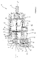
- an electric machine 1 comprising a fixed frame 2 on which are assembled and assembled the various fixed and movable elements for the introduction, retention and deformation of the end of a profile 3 in a specific form.
- the electric machine 1 comprises a single electric motor 4 integral with the frame 2 and providing all the displacements of all the movable elements along the longitudinal axis xx 'of said machine for retaining and deformation of the end of the profile 3 according to a specific form.
- the electric machine 1 comprises moving elements which move along the main axes of symmetries xx 'and yy' of the electric machine 1 or parallel thereto and whose main axis xx 'passes through the profile 3 to be deformed and the motor Electric 4 ( figure 3 ).
- the electric motor 4 is fixed on the frame 2 at one end of the electric machine 1, while opposite the latter and on the same longitudinal axis xx 'the frame 2 is secured to a device to jaws 5 for retaining the profile 3 to deform.
- the jaw device 5 consists of a first clamping jaw said fixed jaw 6 and a second clamping jaw said movable jaw 7.
- the electric machine 1 comprises between the electric motor 4 and the jaw device 5 and centered on the longitudinal axis xx 'a movable thrust trolley 8 which is guided in translation on rails 9 integral with the frame 2.
- the electric motor 4 comprises an output shaft associated with a transmission screw 24 of thrust forces whose free end cooperates with the movable thrust trolley 8 to ensure said carriage its movements along the longitudinal axis xx 'in order to bring it closer or away from the end of the profile 3 to deform.
- the movable thrust trolley 8 comprises, centered on the longitudinal axis xx 'of the electric machine 1, a tool carrier 10 which is slidably mounted on a slide device 11 so that said tool carrier 10 can move relative to the movable carriage thrust 8 in a transverse direction and perpendicular to the longitudinal axis xx '. of the electric machine 1.
- the tool carrier 10 is driven in its displacements by means of an electric jack 12 fixed on the mobile thrust carriage 8.
- the tool holder 10 comprises retaining devices 13 allowing the fixing of punches 14 shaped to ensure the deformation by successive pressures of the free end of the profile 3 retained in the jaw device 5.
- the tool holder 10 comprises between two punches 14 a material-making stop 15 for adjusting the length of the end of the profile 3 to be deformed.
- the movable thrust carriage 8 comprises, shifted laterally with respect to the longitudinal axis xx 'of the electric machine 1, a cam holder 16 carried by a longitudinal axis cc' parallel to the longitudinal axis xx '.
- the cam holder 16 is integral with a cam 17 of rectangular section cooperating as a function of its axial position and longitudinal displacements of the mobile thrust carriage 8 with a clamping device 18 actuating the movable clamping jaw 7 of the jaw device 5.
- the cam holder 16 is rotated about its longitudinal axis cc 'by means of an electric or pneumatic jack 19 fixed on the mobile thrust carriage 8.
- the electric machine 1 comprises on the fixed frame 2 a pre-clamping device 22 consisting of an electric or pneumatic jack 23 acting on the movable clamping jaw 7 of the jaw device 5 to allow pre-clamping of the profile 3 between the jaws 6, 7.
- a pre-clamping device 22 consisting of an electric or pneumatic jack 23 acting on the movable clamping jaw 7 of the jaw device 5 to allow pre-clamping of the profile 3 between the jaws 6, 7.
- the figure 4 shows the adjustment of the length of the end of the profile 3 to be conformed.
- the profile 3 is positioned and held between the jaws 6, 7 of the jaw device 5.
- the tool holder 10 is moved on the movable thrust trolley 8 in a direction parallel to the yy 'axis of the electric machine 1 by the electric or pneumatic cylinder 12 to position the material stopper 15 on the axis xx'.
- the movable thrust trolley 8 is moved by the thrust transmission screw 24 connected to the electric motor 4 in the direction of the end of the profile 3 along the axis xx 'to bring against the end of the profile 3 the stop of take material 15 and adjust the length of the latter depending on the conformation to achieve.
- the cam gate 16 and more particularly the cam 17 is positioned (e) via the electric or pneumatic cylinder 19 in its angular position of smaller dimension so that said cam 17 does not come into operation. contact with the pressure rollers 20, 21 of the clamping device 18.
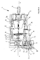
- the figure 5 shows the pre-tightening of the movable clamping jaw 7 of the jaw device 5 around the profile 3 before the deformation of its end.
- the electric or pneumatic cylinder 23 of the pre-clamping device 22 is actuated so that the movable jaw 7 comes to press pre-tightened against the profile 3 in order to maintain the latter between the jaws 6, 7 of the jaw device 5.
- the movable thrust trolley 8 is remote from the end of the profile 3 to be deformed, causing the cam holder 16 and the cam 17 to retract.
- the tool holder 10 After moving the movable thrust trolley 8, the tool holder 10 is moved transversely by means of the electric or pneumatic cylinder 12 along the slide 11 in order to position the first punch 14 on the axis xx 'and in front of the end of the profile 3 to conform.
- the electric or pneumatic cylinder 19 rotates the cam 17 to place the latter in its angular position of larger size.
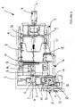
- the figure 6 shows the clamping jaws 6, 7 in the tight position around the profile 3 just before the deformation of its end by means of the punch 14 of the tool holder 10.
- the tight position of the jaw device 5 and more particularly the movable jaw 7 against the profile 3 is obtained by moving the movable thrust trolley 8 towards the end of the profile 3 to be shaped so that the cam 17 disposed in its angular position of greater dimension comes to bear against the pressure rollers 20, 21 of the clamping device 18.
- the introduction of the cam 17 between the pressure rollers 20, 21 makes it possible to act more particularly on the mobile pressure roller 20 so that the latter, because of the dimensions of the cam 17, comes to push on a spring device 25 amplifying the pressure forces of the mobile pressure roller 20. Under the thrust of the mobile pressure roller 20, the spring device 25 exerts an amplified pressure allowing the movable jaw 7 to clamp and lock the profile 3 in the jaw device 5.
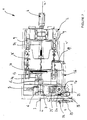
- the figure 7 shows the electric machine 1 in striking position allowing the punch 14 to perform the deformation of the end of the profile 3 in a specific form.
- the punch change 14 is obtained by a retreat of the movable thrust trolley 8.
- the recoil of the movable thrust trolley 8 is provided so as to release only the punch 14 from the end of the profile 3 without completely removing the cam 17 of the rollers pressers 20, 21 for maintaining the pressure force on the spring device 25 and the movable jaw 7 of the jaw device 5.
- the cam 17 has a working length which is sufficient to maintain the pressure rollers 20, 21 in pressure while the movable thrust carriage 8 makes movements of short stroke along the axis xx '.
- the change of punch is obtained by moving the tool carrier in a direction transverse and parallel to the axis yy 'of the electric machine 1 so as to present on the axis xx' another punch 14 of different shape and complementary to continue conformation of the end of the profile 3.
- profiles 3 are positioned between the jaws 6, 7 of the jaw device 5 via a feed device, not shown, for example to automate the supply of the electric machine 1.
- the electric machine 1 is connected to a central programming and control unit, not shown, to act on all the mobile production elements.
- the machine 1 may comprise a protective cap 30 hinged to the fixed frame 2 and coming to close and protect the production area and the moving elements.
- the electrical machine 1 may have a tool carrier 10 with a circular profile rotated about its axis and making it possible to accept a greater number of punches 14 or other tools for shaping the end of the profile 3.
Landscapes
- Engineering & Computer Science (AREA)
- Mechanical Engineering (AREA)
- Hand Tools For Fitting Together And Separating, Or Other Hand Tools (AREA)
- Press Drives And Press Lines (AREA)
Applications Claiming Priority (1)
| Application Number | Priority Date | Filing Date | Title |
|---|---|---|---|
| FR0706500A FR2921003B1 (fr) | 2007-09-17 | 2007-09-17 | Machine electrique pour la deformation des extremites d'un profil. |
Publications (1)
| Publication Number | Publication Date |
|---|---|
| EP2036627A1 true EP2036627A1 (de) | 2009-03-18 |
Family
ID=39052393
Family Applications (1)
| Application Number | Title | Priority Date | Filing Date |
|---|---|---|---|
| EP08356126A Withdrawn EP2036627A1 (de) | 2007-09-17 | 2008-09-16 | Elektrische Maschine zum Verformung von Profilsenden |
Country Status (2)
| Country | Link |
|---|---|
| EP (1) | EP2036627A1 (de) |
| FR (1) | FR2921003B1 (de) |
Cited By (3)
| Publication number | Priority date | Publication date | Assignee | Title |
|---|---|---|---|---|
| ITCO20100054A1 (it) * | 2010-10-12 | 2012-04-13 | Bertini Flii Snc | Regolatore di posizione ottimale relativa alle corse passive di gruppi d'utensili - portautensili |
| EP3922372A1 (de) | 2020-06-09 | 2021-12-15 | Simat SRL | Maschine zum formen von rohrenden |
| CN114043515A (zh) * | 2021-11-26 | 2022-02-15 | 江苏科技大学 | 一种单电机控制的换向夹取装置 |
Citations (5)
| Publication number | Priority date | Publication date | Assignee | Title |
|---|---|---|---|---|
| FR2282953A1 (fr) * | 1974-08-30 | 1976-03-26 | Mannesmann Roehren Werke Ag | Machine pour munir les tubes d'une soie |
| EP1097761A1 (de) * | 1999-11-04 | 2001-05-09 | Financière Robolix, Société à Responsabilité Limitée | Vorrichtung zur Bearbeitung von Rohrenden |
| WO2002013992A1 (de) * | 2000-08-16 | 2002-02-21 | Parker Hannifin Gmbh | Vorrichtung zum umformen eines werkstück-endbereichs |
| WO2003022481A1 (en) * | 2001-09-07 | 2003-03-20 | New Tech S.R.L. | Multipurpose horizontal press having a fixed workpiece-holder for a tubular workpiece to be drawn or tapered |
| US6705148B1 (en) * | 2001-02-23 | 2004-03-16 | Dana Corporation | End-forming of corrugated metal foil wrap tubing |
-
2007
- 2007-09-17 FR FR0706500A patent/FR2921003B1/fr not_active Expired - Fee Related
-
2008
- 2008-09-16 EP EP08356126A patent/EP2036627A1/de not_active Withdrawn
Patent Citations (5)
| Publication number | Priority date | Publication date | Assignee | Title |
|---|---|---|---|---|
| FR2282953A1 (fr) * | 1974-08-30 | 1976-03-26 | Mannesmann Roehren Werke Ag | Machine pour munir les tubes d'une soie |
| EP1097761A1 (de) * | 1999-11-04 | 2001-05-09 | Financière Robolix, Société à Responsabilité Limitée | Vorrichtung zur Bearbeitung von Rohrenden |
| WO2002013992A1 (de) * | 2000-08-16 | 2002-02-21 | Parker Hannifin Gmbh | Vorrichtung zum umformen eines werkstück-endbereichs |
| US6705148B1 (en) * | 2001-02-23 | 2004-03-16 | Dana Corporation | End-forming of corrugated metal foil wrap tubing |
| WO2003022481A1 (en) * | 2001-09-07 | 2003-03-20 | New Tech S.R.L. | Multipurpose horizontal press having a fixed workpiece-holder for a tubular workpiece to be drawn or tapered |
Cited By (4)
| Publication number | Priority date | Publication date | Assignee | Title |
|---|---|---|---|---|
| ITCO20100054A1 (it) * | 2010-10-12 | 2012-04-13 | Bertini Flii Snc | Regolatore di posizione ottimale relativa alle corse passive di gruppi d'utensili - portautensili |
| EP3922372A1 (de) | 2020-06-09 | 2021-12-15 | Simat SRL | Maschine zum formen von rohrenden |
| CN114043515A (zh) * | 2021-11-26 | 2022-02-15 | 江苏科技大学 | 一种单电机控制的换向夹取装置 |
| CN114043515B (zh) * | 2021-11-26 | 2024-01-30 | 江苏科技大学 | 一种单电机控制的换向夹取装置 |
Also Published As
| Publication number | Publication date |
|---|---|
| FR2921003B1 (fr) | 2009-12-18 |
| FR2921003A1 (fr) | 2009-03-20 |
Similar Documents
| Publication | Publication Date | Title |
|---|---|---|
| EP2177292B1 (de) | Vorrichtung zum Richten und Zuführen von einem halbstarren Materialstreifen in eine Maschine | |
| EP0383704A1 (de) | Antriebsvorrichtung für Bahn-, Blatt- oder Drahtmaterial | |
| FR2530980A1 (fr) | Cintreuse a courbures multiples | |
| FR2469964A1 (fr) | Aplanisseur a cylindres | |
| FR2921003A1 (fr) | Machine electrique pour la deformation des extremites d'un profil. | |
| FR2774024A1 (fr) | Plieuse d'une machine rotative a imprimer | |
| FR2509205A1 (fr) | Groupe de cintrage pour tubes et fils metalliques et procede de mise en oeuvre du groupe | |
| FR3121622A1 (fr) | Tete de prehension et de poinçonnage d’une piece permettant son entrainement en rotation pour son usinage | |
| EP0015223A1 (de) | Vorrichtung zum Binden von Drahtspulen | |
| FR2488494A1 (fr) | Procede et appareil pour appliquer des butees d'extremite superieure a une longueur continue de bandes d'accrochage de fermeture a glissiere | |
| FR2772652A1 (fr) | Procede et dispositif de formage de fils metalliques | |
| EP1311356B1 (de) | Vorrichtung zum biegen von rohren | |
| FR2715334A1 (fr) | Machine pour cintrer un matériau se présentant sous une forme sensiblement rectiligne. | |
| FR2619739A1 (fr) | Changeur d'outils pour machine-outil possedant une broche et un magasin d'outils | |
| BE1012430A5 (fr) | Dispositif d'etirage et d'alimentation de fil integre. | |
| FR2639569A1 (fr) | Tete de bridage a rattrapage de jeux | |
| EP0032868B1 (de) | Verfahren und Vorrichtung zur Herstellung eines Werkstücks mit einer Aussparung an seiner Umfangsfläche durch Strangpressen | |
| FR3067645B1 (fr) | Outillage d’emboutissage | |
| EP2324955A1 (de) | Maschine zum Finishen | |
| FR2717109A1 (fr) | Dispositif de pliage d'une tôle le long d'une ligne droite. | |
| FR2746682A1 (fr) | Machine a cambrer les fils metalliques | |
| FR2869829A1 (fr) | Dispositif pour effectuer un changement de plaque sur un cylindre porte-plaques d'une machine d'impression | |
| EP1951993B1 (de) | Verfahren zum halten und montieren eines objekts und entsprechendes verfahren | |
| FR2769253A1 (fr) | Dispositif de bridage rotatif pour l'usinage de profile | |
| FR2822736A1 (fr) | Procede de fabrication d'un element en fil metallique |
Legal Events
| Date | Code | Title | Description |
|---|---|---|---|
| PUAI | Public reference made under article 153(3) epc to a published international application that has entered the european phase |
Free format text: ORIGINAL CODE: 0009012 |
|
| AK | Designated contracting states |
Kind code of ref document: A1 Designated state(s): AT BE BG CH CY CZ DE DK EE ES FI FR GB GR HR HU IE IS IT LI LT LU LV MC MT NL NO PL PT RO SE SI SK TR |
|
| AX | Request for extension of the european patent |
Extension state: AL BA MK RS |
|
| AKX | Designation fees paid | ||
| REG | Reference to a national code |
Ref country code: DE Ref legal event code: 8566 |
|
| STAA | Information on the status of an ep patent application or granted ep patent |
Free format text: STATUS: THE APPLICATION IS DEEMED TO BE WITHDRAWN |
|
| 18D | Application deemed to be withdrawn |
Effective date: 20090919 |