EP2036628B1 - Procédé et dispositif de fabrication d'une pièce à usiner comprenant des courbures à l'aide d'un fluide sous pression - Google Patents
Procédé et dispositif de fabrication d'une pièce à usiner comprenant des courbures à l'aide d'un fluide sous pression Download PDFInfo
- Publication number
- EP2036628B1 EP2036628B1 EP08016051A EP08016051A EP2036628B1 EP 2036628 B1 EP2036628 B1 EP 2036628B1 EP 08016051 A EP08016051 A EP 08016051A EP 08016051 A EP08016051 A EP 08016051A EP 2036628 B1 EP2036628 B1 EP 2036628B1
- Authority
- EP
- European Patent Office
- Prior art keywords
- workpiece
- pressure medium
- mold
- base plate
- mold halves
- Prior art date
- Legal status (The legal status is an assumption and is not a legal conclusion. Google has not performed a legal analysis and makes no representation as to the accuracy of the status listed.)
- Not-in-force
Links
Images

Classifications
-
- B—PERFORMING OPERATIONS; TRANSPORTING
- B21—MECHANICAL METAL-WORKING WITHOUT ESSENTIALLY REMOVING MATERIAL; PUNCHING METAL
- B21D—WORKING OR PROCESSING OF SHEET METAL OR METAL TUBES, RODS OR PROFILES WITHOUT ESSENTIALLY REMOVING MATERIAL; PUNCHING METAL
- B21D26/00—Shaping without cutting otherwise than using rigid devices or tools or yieldable or resilient pads, i.e. applying fluid pressure or magnetic forces
- B21D26/02—Shaping without cutting otherwise than using rigid devices or tools or yieldable or resilient pads, i.e. applying fluid pressure or magnetic forces by applying fluid pressure
- B21D26/033—Deforming tubular bodies
- B21D26/047—Mould construction
-
- B—PERFORMING OPERATIONS; TRANSPORTING
- B21—MECHANICAL METAL-WORKING WITHOUT ESSENTIALLY REMOVING MATERIAL; PUNCHING METAL
- B21D—WORKING OR PROCESSING OF SHEET METAL OR METAL TUBES, RODS OR PROFILES WITHOUT ESSENTIALLY REMOVING MATERIAL; PUNCHING METAL
- B21D26/00—Shaping without cutting otherwise than using rigid devices or tools or yieldable or resilient pads, i.e. applying fluid pressure or magnetic forces
- B21D26/02—Shaping without cutting otherwise than using rigid devices or tools or yieldable or resilient pads, i.e. applying fluid pressure or magnetic forces by applying fluid pressure
- B21D26/033—Deforming tubular bodies
- B21D26/039—Means for controlling the clamping or opening of the moulds
-
- B—PERFORMING OPERATIONS; TRANSPORTING
- B21—MECHANICAL METAL-WORKING WITHOUT ESSENTIALLY REMOVING MATERIAL; PUNCHING METAL
- B21D—WORKING OR PROCESSING OF SHEET METAL OR METAL TUBES, RODS OR PROFILES WITHOUT ESSENTIALLY REMOVING MATERIAL; PUNCHING METAL
- B21D39/00—Application of procedures in order to connect objects or parts, e.g. coating with sheet metal otherwise than by plating; Tube expanders
- B21D39/08—Tube expanders
- B21D39/20—Tube expanders with mandrels, e.g. expandable
- B21D39/203—Tube expanders with mandrels, e.g. expandable expandable by fluid or elastic material
Definitions
- the ends of the workpiece sealingly engage in a recess of the hydroforming die enclosing a cone, wherein subsequently a pressure medium for generating an internal pressure in the hollow profile-shaped workpiece to be deformed is fed in by a feed provided in the first mold half.
- a pressure medium for generating an internal pressure in the hollow profile-shaped workpiece to be deformed is fed in by a feed provided in the first mold half.
- a corresponding pressure booster is required to increase the internal pressure.
- the tool halves continue to press together under pressure until the tool is closed, whereby the workpiece has created to realize its final shape of the engraving / negative mold of the tool.
- a vent hole for the pressure medium is in the second mold half, which may be a virtually incompressible liquid, such as water or a water-oil mixture.
- a disadvantage of this solution is that the filling of the workpiece cavity with the printing medium as an independent, the cycle time increasing process can be done after inserting the workpiece in the tool, with the ends of the workpiece by moving the mold halves already in its sealing position in the recess the tool halves must be located. There is a risk that the workpiece buckles and comes to rest in the division plane between the tool halves. In addition, a series-steady insertion of the workpieces is not guaranteed because the cones alone do not contribute enough to the orthogonal guidance of the workpiece. Ultimately, the removal of the workpieces causes difficulties in that they can jam in the recess of one of the two mold halves. To increase the internal pressure, a pressure booster is necessary for the direct pressurization.
- the object of the invention is to propose a solution in which the filling of the cavity of the workpiece with the printing medium as a separate, the cycle time increasing process can be dispensed with, as well as to the already required at this time realization of the sealing position at the ends of the workpiece.
- a buckling of the workpiece is excluded, created the conditions for a reliable insertion of the workpiece and the trouble-free removal of the workpiece are possible.
- no pressure booster should be required for the increase of the internal pressure.
- the advantages of the invention are that can be dispensed with the filling medium of the workpiece with the pressure medium as a separate, the cycle time increasing process, because this when inserting into the already located in the pressure medium of the container lower mold half of the device completely with the print medium is filled.
- the realization of the sealing position at the ends of the workpiece is not required at this time.
- a buckling of the workpiece is prevented, created the conditions for a reliable insertion of the workpieces and allows easy removal of the workpieces.
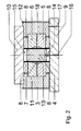
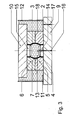
- a device 1 for producing a bulge 2 ( Fig. 3 ) having workpiece 3 by means of a pressure medium 11.
- This device 1 consists of two transverse to the longitudinal axis 4 of the workpiece 3 divided tool halves, the lower mold half 5 and the upper mold half 6, which have a later final shape of the workpiece corresponding engraving / negative mold 7.
- the tool halves 5, 6 are associated with distance springs 8, via which they are each connected to a lower tool base plate 9 and an upper tool base plate 10.
- the tool base plates 9, 10 cooperate with a press, not shown.
- the lower tool base plate 9 is associated with a used as a pressure medium 11 incompressible liquid, preferably water, filled container 12, in which at least the workpiece 3 is completely immersed.
- the lower and upper mold base plates 9, 10 each have a (lower and upper) punch 14, 15 for the mutual engagement in the cavity 13 of the workpiece 3.
- a channel 16 is arranged in the lower tool base plate 9 and its punch 14.
- the lower tool base plate 9 includes an inlet and outlet 17 for the incompressible fluid used as the pressure medium 11. This inlet and outlet 17 can also be arranged on the container 12.
- at least one of the tool halves 5, 6 is equipped with a displacement channel 18 for the pressure medium 11, as a result of which the liquid pressure medium 11 can escape from the space between the workpiece 3 and the engraved / negative mold 7.
- this displacement channel 18 is arranged in the dividing plane between the two mold halves 5, 6.
Landscapes
- Engineering & Computer Science (AREA)
- Mechanical Engineering (AREA)
- Physics & Mathematics (AREA)
- Fluid Mechanics (AREA)
- Shaping Metal By Deep-Drawing, Or The Like (AREA)
Claims (7)
- Procédé et dispositif de fabrication d'une pièce à usiner (3) comprenant deux courbures à l'aide d'un fluide sous pression (11), ladite pièce à usiner étant une pièce de profil creux qui elle est insérée de façon planimétrique dans un outil de formage consistant de deux moitiés (5, 6) disposées en sens transversal par rapport à l'axe longitudinal, cet outil présentant une gravure/une forme non moulée qui correspond à la forme postérieure et définitive de la pièce à usiner (3) où, après le serrage des deux moitiés d'outil (5, 6), les bouts de la pièce à usiner (3) sont rendus étanches avant d'appliquer à la pièce à usiner (3) une force de compression axiale et où, en augmentant la pression d'un fluide sous pression (11) qui se trouve dans le creux de la pièce à usiner (3), cette pièce à usiner (3) se met, à l'aide d'un liquide incompressible, contre la gravure/une forme non moulée de l'outil de formage afin de prendre sa forma définitive,
caractérisé en ce
que la pièce à usiner (3) est insérée dans l'une des deux moitiés (5) de l'outil de formage, que ladite moitié d'outil (5) est située dans un récipient (12) rempli d'un liquide incompressible, en l'occurrence du fluide sous pression (11), de sorte qu'au moins la pièce à usiner (3) sera complètement imbibée et entourée du liquide. Ensuite, les deux moitiés d'outil (5, 6) sont serrées, ce qui fait que les poinçons (14, 15) disposés tant au-dessus des bouts de la pièce à usiner (3) situés dans le creux (13) étanche et engrenant qu'au niveau de la plaque de base supérieure et inférieure de formage (9, 10) commencent à refouler le fluide sous pression (11), que les deux moitiés d'outil (5, 6) gardent, au moyen de ressorts d'écartement (8), une distance déterminée de la plaque de base supérieure et inférieure de formage (9, 10), et que, grâce à une force de compression appliquée à ces ressorts d'écartement (8), les deux moitiés d'outil (5, 6) entrent en contact aussi bien l'une avec l'autre qu'avec la plaque de base de formage (9, 10) respective, ce qui fait que, grâce au refoulement continu du fluide sous pression (11), le procédé de formage ayant pour but la réalisation de la forme définitive de la pièce à usiner (3) soit fini. - Procédé suivant la revendication 2,
caractérisé en ce
que le fluide liquide sous pression (11) presque entièrement incompressible est de l'eau. - Dispositif pour fabriquer une pièce à usiner comprenant de courbures à l'aide d'un fluide sous pression, ce dispositif consistant de deux moitiés d'outil (5, 6) disposées en sens transversal par rapport à l'axe longitudinal (4) de la pièce à usiner (3) qui elles présentent une gravure/une forme non moulée (7) correspondant à la forme postérieure et définitive de la pièce à usiner (3).
caractérisé en ce
que les deux moitiés d'outil (5, 6) sont dotées de ressorts d'écartement (8) qui eux relient les deux moitiés à une plaque de base supérieure et inférieure de formage (9, 10), la plaque de base inférieure de formage (9) étant munie d'un récipient (12) qui lui est rempli d'un liquide incompressible, en l'occurrence du fluide sous pression (11), dans lequel au moins la pièce à usiner (3) est complètement immergée et où, afin d'assurer l'engrenage dans le creux (13) de la pièce à usiner (3), chacune des plaques de base supérieure et inférieure de formage (9, 10) est équipée d'un poinçon (14, 15). - Dispositif suivant la revendication 3,
caractérisé en ce
que dans la plaque de base inférieure de formage (9) et dans son poinçon (14) respectif est disposé un canal (16) pour un clapet de surpression. - Dispositif suivant la revendication 3,
caractérisé en ce
que la plaque de base inférieure de formage (9) ou le récipient (12) sont dotés d'un canal d'amenée et de sortie (14) pour le fluide sous pression (11). - Dispositif suivant la revendication 3,
caractérisé en ce
qu'au moins l'une des deux moitiés d'outil (5, 6) comprend un canal de refoulement (18) pour le fluide sous pression (11). - Dispositif suivant la revendication 6,
caractérisé en ce
que la canal de refoulement (18) est disposé au niveau du plan d'engrenage situé entre les deux moitiés d'outil (5, 6).
Applications Claiming Priority (1)
| Application Number | Priority Date | Filing Date | Title |
|---|---|---|---|
| DE102007043316A DE102007043316B4 (de) | 2007-09-12 | 2007-09-12 | Verfahren und Vorrichtung zur Herstellung eines Ausbuchtungen aufweisenden Werkstückes mittels eines Druckmediums |
Publications (2)
| Publication Number | Publication Date |
|---|---|
| EP2036628A1 EP2036628A1 (fr) | 2009-03-18 |
| EP2036628B1 true EP2036628B1 (fr) | 2010-05-05 |
Family
ID=40223746
Family Applications (1)
| Application Number | Title | Priority Date | Filing Date |
|---|---|---|---|
| EP08016051A Not-in-force EP2036628B1 (fr) | 2007-09-12 | 2008-09-11 | Procédé et dispositif de fabrication d'une pièce à usiner comprenant des courbures à l'aide d'un fluide sous pression |
Country Status (4)
| Country | Link |
|---|---|
| EP (1) | EP2036628B1 (fr) |
| AT (1) | ATE466675T1 (fr) |
| DE (2) | DE102007043316B4 (fr) |
| ES (1) | ES2345853T3 (fr) |
Families Citing this family (4)
| Publication number | Priority date | Publication date | Assignee | Title |
|---|---|---|---|---|
| DE102009030089B3 (de) * | 2009-06-22 | 2010-11-11 | Benteler Automobiltechnik Gmbh | Verfahren zur Innenhochdruckumformung |
| DE102011052888A1 (de) * | 2011-08-22 | 2013-02-28 | Benteler Automobiltechnik Gmbh | Verfahren zur Umformung eines Hohlprofils für ein Kraftfahrzeug |
| DE102011116993B4 (de) | 2011-10-26 | 2024-07-25 | Cellcentric Gmbh & Co. Kg | Verfahren und Vorrichtung zur Herstellung eines metallischen Folienbauteiles, insbesondere einer Brennstoffzellenkomponente |
| CN102423784A (zh) * | 2011-11-08 | 2012-04-25 | 哈尔滨工程大学 | 基于弹性介质的形状记忆合金管接头扩径装置及方法 |
Family Cites Families (7)
| Publication number | Priority date | Publication date | Assignee | Title |
|---|---|---|---|---|
| US3625040A (en) * | 1969-08-06 | 1971-12-07 | Koppy Tool Corp | Method and apparatus for forming articles from a tubular blank |
| DE4017072A1 (de) * | 1990-05-26 | 1991-11-28 | Benteler Werke Ag | Verfahren zum hydraulischen umformen eines rohrfoermigen hohlkoerpers und vorrichtung zur durchfuehrung des verfahrens |
| DE4337517A1 (de) * | 1993-11-03 | 1995-05-04 | Klaas Friedrich | Verfahren zum Innenhochdruck-Umformen von hohlen abgesetzten Wellen aus kaltumformbarem Metall |
| US6128936A (en) * | 1998-09-09 | 2000-10-10 | Kabushiki Kaisha Opton | Bulging device and bulging method |
| TWI267410B (en) * | 2002-11-08 | 2006-12-01 | Mitsubishi Motors Corp | Deformed element pipe for hydraulic bulging, hydraulic bulging device using the element pipe, hydraulic bulging method using the element pipe, and hydraulic-bulged product |
| DE10357341B4 (de) * | 2003-12-09 | 2006-02-09 | Daimlerchrysler Ag | Vorrichtung und Verfahren zur Innenhochdruckumformung eines Rohlings |
| DE102005036419B4 (de) * | 2005-07-29 | 2015-05-21 | Tower Automotive Hydroforming Gmbh & Co. Kg | Vorrichtung zur Herstellung ausgebauchter Hohlprofile, insbesondere von Gasgeneratorgehäusen für Airbageinrichtungen |
-
2007
- 2007-09-12 DE DE102007043316A patent/DE102007043316B4/de not_active Expired - Fee Related
-
2008
- 2008-09-11 DE DE502008000612T patent/DE502008000612D1/de active Active
- 2008-09-11 AT AT08016051T patent/ATE466675T1/de active
- 2008-09-11 EP EP08016051A patent/EP2036628B1/fr not_active Not-in-force
- 2008-09-11 ES ES08016051T patent/ES2345853T3/es active Active
Also Published As
| Publication number | Publication date |
|---|---|
| DE102007043316B4 (de) | 2009-08-20 |
| EP2036628A1 (fr) | 2009-03-18 |
| ATE466675T1 (de) | 2010-05-15 |
| DE102007043316A1 (de) | 2009-03-19 |
| ES2345853T3 (es) | 2010-10-04 |
| DE502008000612D1 (de) | 2010-06-17 |
Similar Documents
| Publication | Publication Date | Title |
|---|---|---|
| DE2642963A1 (de) | Einspannvorrichtung | |
| EP2036628B1 (fr) | Procédé et dispositif de fabrication d'une pièce à usiner comprenant des courbures à l'aide d'un fluide sous pression | |
| DE19717953A1 (de) | Verfahren zum hydromechanischen Stülpziehen von Metallblechen | |
| DE19833006B4 (de) | Verfahren und Vorrichtung zur Herstellung rohrförmiger gebogener Hohlkörper durch Innenhochdruckumformen | |
| DE10230284B4 (de) | Verfahren und Vorrichtung zur Befestigung von Bauteilen an umfänglich geschlossensn Hohlprofilen | |
| DE10164662B4 (de) | Vorrichtung und Verfahren zum hydromechanischen Tiefziehen | |
| DE10248329A1 (de) | Verfahren und Vorrichtung zum wirkmedienbasierten Umformen eines Bauteilrohling | |
| EP2076342B1 (fr) | Dispositif de déformation sous haute pression intérieure | |
| EP1216769B1 (fr) | Pocédé et dispositif de fabrication d' un profilé creux fermé | |
| EP1207974B1 (fr) | Procede et outillage d'emboutissage profond | |
| DE602004003986T2 (de) | Verfahren zum Umformen von rohrförmigen Werkstücken mit einem segmentierten Werkzeug | |
| EP0865845A1 (fr) | Procédé pour maintenir ensemble moules ou matrices en deux parties soumises à pression interne et dispositif pour la mise en oeuvre du procédé | |
| DE10048005B4 (de) | Vorrichtung zum Verbinden mindestens zweier flächiger, übereinander liegender Bauteile | |
| DE102004028078B4 (de) | Verfahren und Vorrichtung zum Ausbilden eines Kragenabschnitts an einem Werkstück | |
| DE102005036377B4 (de) | Vorrichtung und Verfahren zur Formgebung eines Werkstückes | |
| DE19533828C2 (de) | Vorrichtung zum Innenhochdruckumformen von rohrförmigen Rohlingen | |
| DE19955518B4 (de) | Etagenumformwerkzeug für eine Innenhochdruck-Umformpresse | |
| EP2332667B1 (fr) | Procédé de fabrication de composants selon la technique de formage sous haute pression interne | |
| DE10030792C2 (de) | Mehrstufenpresse, insbesondere Quertransportpresse, mit hydraulischer Schließvorrichtung | |
| DE2402190B2 (de) | Vorrichtung zum biegen von stahlblechen bzw. -platten | |
| DE102007017030B3 (de) | Verfahren und Vorrichtung zum Herstellen eines Innenhochdruckumformteils | |
| DE102005000852B4 (de) | Verfahren und Vorrichtung zur Herstellung eines umfänglich geschlossenen Hohlprofils | |
| DE19911364C2 (de) | Verfahren und Vorrichtung zur Abdichtung der Enden von Hohlprofilen beim Innenhochdruckumformverfahren | |
| DE102005050202A1 (de) | Blechteil mit partiellen Verstärkungselementen hergestellt nach dem Außenhochdruckumformverfahren | |
| WO2005092535A1 (fr) | Dispositif de moulage interne haute pression |
Legal Events
| Date | Code | Title | Description |
|---|---|---|---|
| PUAI | Public reference made under article 153(3) epc to a published international application that has entered the european phase |
Free format text: ORIGINAL CODE: 0009012 |
|
| AK | Designated contracting states |
Kind code of ref document: A1 Designated state(s): AT BE BG CH CY CZ DE DK EE ES FI FR GB GR HR HU IE IS IT LI LT LU LV MC MT NL NO PL PT RO SE SI SK TR |
|
| AX | Request for extension of the european patent |
Extension state: AL BA MK RS |
|
| 17P | Request for examination filed |
Effective date: 20090902 |
|
| GRAP | Despatch of communication of intention to grant a patent |
Free format text: ORIGINAL CODE: EPIDOSNIGR1 |
|
| AKX | Designation fees paid |
Designated state(s): AT BE BG CH CY CZ DE DK EE ES FI FR GB GR HR HU IE IS IT LI LT LU LV MC MT NL NO PL PT RO SE SI SK TR |
|
| GRAS | Grant fee paid |
Free format text: ORIGINAL CODE: EPIDOSNIGR3 |
|
| GRAA | (expected) grant |
Free format text: ORIGINAL CODE: 0009210 |
|
| AK | Designated contracting states |
Kind code of ref document: B1 Designated state(s): AT BE BG CH CY CZ DE DK EE ES FI FR GB GR HR HU IE IS IT LI LT LU LV MC MT NL NO PL PT RO SE SI SK TR |
|
| REG | Reference to a national code |
Ref country code: GB Ref legal event code: FG4D Free format text: NOT ENGLISH |
|
| REG | Reference to a national code |
Ref country code: CH Ref legal event code: EP |
|
| REG | Reference to a national code |
Ref country code: IE Ref legal event code: FG4D Free format text: LANGUAGE OF EP DOCUMENT: GERMAN |
|
| REF | Corresponds to: |
Ref document number: 502008000612 Country of ref document: DE Date of ref document: 20100617 Kind code of ref document: P |
|
| REG | Reference to a national code |
Ref country code: NL Ref legal event code: VDEP Effective date: 20100505 |
|
| REG | Reference to a national code |
Ref country code: SE Ref legal event code: TRGR |
|
| REG | Reference to a national code |
Ref country code: ES Ref legal event code: FG2A Ref document number: 2345853 Country of ref document: ES Kind code of ref document: T3 |
|
| LTIE | Lt: invalidation of european patent or patent extension |
Effective date: 20100505 |
|
| PG25 | Lapsed in a contracting state [announced via postgrant information from national office to epo] |
Ref country code: LT Free format text: LAPSE BECAUSE OF FAILURE TO SUBMIT A TRANSLATION OF THE DESCRIPTION OR TO PAY THE FEE WITHIN THE PRESCRIBED TIME-LIMIT Effective date: 20100505 Ref country code: NL Free format text: LAPSE BECAUSE OF FAILURE TO SUBMIT A TRANSLATION OF THE DESCRIPTION OR TO PAY THE FEE WITHIN THE PRESCRIBED TIME-LIMIT Effective date: 20100505 Ref country code: NO Free format text: LAPSE BECAUSE OF FAILURE TO SUBMIT A TRANSLATION OF THE DESCRIPTION OR TO PAY THE FEE WITHIN THE PRESCRIBED TIME-LIMIT Effective date: 20100805 |
|
| REG | Reference to a national code |
Ref country code: SK Ref legal event code: T3 Ref document number: E 7628 Country of ref document: SK |
|
| PG25 | Lapsed in a contracting state [announced via postgrant information from national office to epo] |
Ref country code: FI Free format text: LAPSE BECAUSE OF FAILURE TO SUBMIT A TRANSLATION OF THE DESCRIPTION OR TO PAY THE FEE WITHIN THE PRESCRIBED TIME-LIMIT Effective date: 20100505 Ref country code: SI Free format text: LAPSE BECAUSE OF FAILURE TO SUBMIT A TRANSLATION OF THE DESCRIPTION OR TO PAY THE FEE WITHIN THE PRESCRIBED TIME-LIMIT Effective date: 20100505 Ref country code: LV Free format text: LAPSE BECAUSE OF FAILURE TO SUBMIT A TRANSLATION OF THE DESCRIPTION OR TO PAY THE FEE WITHIN THE PRESCRIBED TIME-LIMIT Effective date: 20100505 Ref country code: IS Free format text: LAPSE BECAUSE OF FAILURE TO SUBMIT A TRANSLATION OF THE DESCRIPTION OR TO PAY THE FEE WITHIN THE PRESCRIBED TIME-LIMIT Effective date: 20100905 Ref country code: HR Free format text: LAPSE BECAUSE OF FAILURE TO SUBMIT A TRANSLATION OF THE DESCRIPTION OR TO PAY THE FEE WITHIN THE PRESCRIBED TIME-LIMIT Effective date: 20100505 |
|
| REG | Reference to a national code |
Ref country code: IE Ref legal event code: FD4D |
|
| REG | Reference to a national code |
Ref country code: HU Ref legal event code: AG4A Ref document number: E008692 Country of ref document: HU |
|
| PG25 | Lapsed in a contracting state [announced via postgrant information from national office to epo] |
Ref country code: CY Free format text: LAPSE BECAUSE OF FAILURE TO SUBMIT A TRANSLATION OF THE DESCRIPTION OR TO PAY THE FEE WITHIN THE PRESCRIBED TIME-LIMIT Effective date: 20100609 Ref country code: PL Free format text: LAPSE BECAUSE OF FAILURE TO SUBMIT A TRANSLATION OF THE DESCRIPTION OR TO PAY THE FEE WITHIN THE PRESCRIBED TIME-LIMIT Effective date: 20100505 |
|
| RAP2 | Party data changed (patent owner data changed or rights of a patent transferred) |
Owner name: FISCHER HYDROFORMING GMBH |
|
| RIN2 | Information on inventor provided after grant (corrected) |
Inventor name: SCHULZE, BERND |
|
| PG25 | Lapsed in a contracting state [announced via postgrant information from national office to epo] |
Ref country code: DK Free format text: LAPSE BECAUSE OF FAILURE TO SUBMIT A TRANSLATION OF THE DESCRIPTION OR TO PAY THE FEE WITHIN THE PRESCRIBED TIME-LIMIT Effective date: 20100505 Ref country code: IE Free format text: LAPSE BECAUSE OF FAILURE TO SUBMIT A TRANSLATION OF THE DESCRIPTION OR TO PAY THE FEE WITHIN THE PRESCRIBED TIME-LIMIT Effective date: 20100505 Ref country code: EE Free format text: LAPSE BECAUSE OF FAILURE TO SUBMIT A TRANSLATION OF THE DESCRIPTION OR TO PAY THE FEE WITHIN THE PRESCRIBED TIME-LIMIT Effective date: 20100505 |
|
| PG25 | Lapsed in a contracting state [announced via postgrant information from national office to epo] |
Ref country code: RO Free format text: LAPSE BECAUSE OF FAILURE TO SUBMIT A TRANSLATION OF THE DESCRIPTION OR TO PAY THE FEE WITHIN THE PRESCRIBED TIME-LIMIT Effective date: 20100505 |
|
| PLBE | No opposition filed within time limit |
Free format text: ORIGINAL CODE: 0009261 |
|
| STAA | Information on the status of an ep patent application or granted ep patent |
Free format text: STATUS: NO OPPOSITION FILED WITHIN TIME LIMIT |
|
| BERE | Be: lapsed |
Owner name: SCHULZE, BERND Effective date: 20100930 |
|
| 26N | No opposition filed |
Effective date: 20110208 |
|
| REG | Reference to a national code |
Ref country code: DE Ref legal event code: R081 Ref document number: 502008000612 Country of ref document: DE Owner name: FISCHER HYDROFORMING GMBH, DE Free format text: FORMER OWNER: SCHULZE, BERND, DR., 09366 NIEDERDORF, DE Effective date: 20110214 |
|
| PG25 | Lapsed in a contracting state [announced via postgrant information from national office to epo] |
Ref country code: MC Free format text: LAPSE BECAUSE OF NON-PAYMENT OF DUE FEES Effective date: 20100930 |
|
| REG | Reference to a national code |
Ref country code: DE Ref legal event code: R097 Ref document number: 502008000612 Country of ref document: DE Effective date: 20110207 |
|
| PG25 | Lapsed in a contracting state [announced via postgrant information from national office to epo] |
Ref country code: GR Free format text: LAPSE BECAUSE OF FAILURE TO SUBMIT A TRANSLATION OF THE DESCRIPTION OR TO PAY THE FEE WITHIN THE PRESCRIBED TIME-LIMIT Effective date: 20100806 |
|
| PG25 | Lapsed in a contracting state [announced via postgrant information from national office to epo] |
Ref country code: BE Free format text: LAPSE BECAUSE OF NON-PAYMENT OF DUE FEES Effective date: 20100930 |
|
| PG25 | Lapsed in a contracting state [announced via postgrant information from national office to epo] |
Ref country code: MT Free format text: LAPSE BECAUSE OF FAILURE TO SUBMIT A TRANSLATION OF THE DESCRIPTION OR TO PAY THE FEE WITHIN THE PRESCRIBED TIME-LIMIT Effective date: 20100505 |
|
| PG25 | Lapsed in a contracting state [announced via postgrant information from national office to epo] |
Ref country code: BG Free format text: LAPSE BECAUSE OF FAILURE TO SUBMIT A TRANSLATION OF THE DESCRIPTION OR TO PAY THE FEE WITHIN THE PRESCRIBED TIME-LIMIT Effective date: 20100505 Ref country code: LU Free format text: LAPSE BECAUSE OF NON-PAYMENT OF DUE FEES Effective date: 20100911 |
|
| PG25 | Lapsed in a contracting state [announced via postgrant information from national office to epo] |
Ref country code: TR Free format text: LAPSE BECAUSE OF FAILURE TO SUBMIT A TRANSLATION OF THE DESCRIPTION OR TO PAY THE FEE WITHIN THE PRESCRIBED TIME-LIMIT Effective date: 20100505 |
|
| REG | Reference to a national code |
Ref country code: CH Ref legal event code: PL |
|
| GBPC | Gb: european patent ceased through non-payment of renewal fee |
Effective date: 20120911 |
|
| PG25 | Lapsed in a contracting state [announced via postgrant information from national office to epo] |
Ref country code: LI Free format text: LAPSE BECAUSE OF NON-PAYMENT OF DUE FEES Effective date: 20120930 Ref country code: PT Free format text: LAPSE BECAUSE OF NON-PAYMENT OF DUE FEES Effective date: 20100505 Ref country code: CH Free format text: LAPSE BECAUSE OF NON-PAYMENT OF DUE FEES Effective date: 20120930 Ref country code: GB Free format text: LAPSE BECAUSE OF NON-PAYMENT OF DUE FEES Effective date: 20120911 |
|
| PG25 | Lapsed in a contracting state [announced via postgrant information from national office to epo] |
Ref country code: BG Free format text: LAPSE BECAUSE OF FAILURE TO SUBMIT A TRANSLATION OF THE DESCRIPTION OR TO PAY THE FEE WITHIN THE PRESCRIBED TIME-LIMIT Effective date: 20100805 |
|
| REG | Reference to a national code |
Ref country code: FR Ref legal event code: PLFP Year of fee payment: 8 |
|
| REG | Reference to a national code |
Ref country code: FR Ref legal event code: PLFP Year of fee payment: 9 |
|
| REG | Reference to a national code |
Ref country code: FR Ref legal event code: PLFP Year of fee payment: 10 |
|
| REG | Reference to a national code |
Ref country code: FR Ref legal event code: PLFP Year of fee payment: 11 |
|
| PGFP | Annual fee paid to national office [announced via postgrant information from national office to epo] |
Ref country code: CZ Payment date: 20230830 Year of fee payment: 16 Ref country code: AT Payment date: 20230915 Year of fee payment: 16 |
|
| PGFP | Annual fee paid to national office [announced via postgrant information from national office to epo] |
Ref country code: SK Payment date: 20230905 Year of fee payment: 16 Ref country code: SE Payment date: 20230921 Year of fee payment: 16 Ref country code: HU Payment date: 20230911 Year of fee payment: 16 Ref country code: FR Payment date: 20230918 Year of fee payment: 16 Ref country code: DE Payment date: 20230609 Year of fee payment: 16 |
|
| PGFP | Annual fee paid to national office [announced via postgrant information from national office to epo] |
Ref country code: ES Payment date: 20231019 Year of fee payment: 16 |
|
| PGFP | Annual fee paid to national office [announced via postgrant information from national office to epo] |
Ref country code: IT Payment date: 20230929 Year of fee payment: 16 |
|
| REG | Reference to a national code |
Ref country code: DE Ref legal event code: R119 Ref document number: 502008000612 Country of ref document: DE |
|
| REG | Reference to a national code |
Ref country code: SK Ref legal event code: MM4A Ref document number: E 7628 Country of ref document: SK Effective date: 20240911 |
|
| PG25 | Lapsed in a contracting state [announced via postgrant information from national office to epo] |
Ref country code: CZ Free format text: LAPSE BECAUSE OF NON-PAYMENT OF DUE FEES Effective date: 20240911 |
|
| REG | Reference to a national code |
Ref country code: SE Ref legal event code: EUG |
|
| REG | Reference to a national code |
Ref country code: AT Ref legal event code: MM01 Ref document number: 466675 Country of ref document: AT Kind code of ref document: T Effective date: 20240911 |
|
| PG25 | Lapsed in a contracting state [announced via postgrant information from national office to epo] |
Ref country code: DE Free format text: LAPSE BECAUSE OF NON-PAYMENT OF DUE FEES Effective date: 20250401 |
|
| PG25 | Lapsed in a contracting state [announced via postgrant information from national office to epo] |
Ref country code: HU Free format text: LAPSE BECAUSE OF NON-PAYMENT OF DUE FEES Effective date: 20240912 |
|
| PG25 | Lapsed in a contracting state [announced via postgrant information from national office to epo] |
Ref country code: IT Free format text: LAPSE BECAUSE OF NON-PAYMENT OF DUE FEES Effective date: 20240911 |
|
| PG25 | Lapsed in a contracting state [announced via postgrant information from national office to epo] |
Ref country code: FR Free format text: LAPSE BECAUSE OF NON-PAYMENT OF DUE FEES Effective date: 20240930 |
|
| PG25 | Lapsed in a contracting state [announced via postgrant information from national office to epo] |
Ref country code: AT Free format text: LAPSE BECAUSE OF NON-PAYMENT OF DUE FEES Effective date: 20240911 |
|
| PG25 | Lapsed in a contracting state [announced via postgrant information from national office to epo] |
Ref country code: SK Free format text: LAPSE BECAUSE OF NON-PAYMENT OF DUE FEES Effective date: 20240911 |
|
| PG25 | Lapsed in a contracting state [announced via postgrant information from national office to epo] |
Ref country code: SE Free format text: LAPSE BECAUSE OF NON-PAYMENT OF DUE FEES Effective date: 20240912 |
|
| REG | Reference to a national code |
Ref country code: ES Ref legal event code: FD2A Effective date: 20251030 |
|
| PG25 | Lapsed in a contracting state [announced via postgrant information from national office to epo] |
Ref country code: ES Free format text: LAPSE BECAUSE OF NON-PAYMENT OF DUE FEES Effective date: 20240912 |