EP2076342B1 - Dispositif de déformation sous haute pression intérieure - Google Patents
Dispositif de déformation sous haute pression intérieure Download PDFInfo
- Publication number
- EP2076342B1 EP2076342B1 EP07818541A EP07818541A EP2076342B1 EP 2076342 B1 EP2076342 B1 EP 2076342B1 EP 07818541 A EP07818541 A EP 07818541A EP 07818541 A EP07818541 A EP 07818541A EP 2076342 B1 EP2076342 B1 EP 2076342B1
- Authority
- EP
- European Patent Office
- Prior art keywords
- carriage
- workpiece
- mold
- drive
- guide
- Prior art date
- Legal status (The legal status is an assumption and is not a legal conclusion. Google has not performed a legal analysis and makes no representation as to the accuracy of the status listed.)
- Not-in-force
Links
- 230000008878 coupling Effects 0.000 claims abstract description 9
- 238000010168 coupling process Methods 0.000 claims abstract description 9
- 238000005859 coupling reaction Methods 0.000 claims abstract description 9
- 238000007789 sealing Methods 0.000 claims description 18
- 230000005540 biological transmission Effects 0.000 abstract description 2
- 238000000926 separation method Methods 0.000 abstract description 2
- 238000000465 moulding Methods 0.000 description 12
- 238000006073 displacement reaction Methods 0.000 description 11
- 239000012530 fluid Substances 0.000 description 9
- 238000000034 method Methods 0.000 description 7
- 230000000694 effects Effects 0.000 description 6
- 230000008569 process Effects 0.000 description 6
- 238000006243 chemical reaction Methods 0.000 description 4
- 230000005489 elastic deformation Effects 0.000 description 4
- 239000007788 liquid Substances 0.000 description 3
- 230000015572 biosynthetic process Effects 0.000 description 2
- 239000000463 material Substances 0.000 description 2
- 238000003825 pressing Methods 0.000 description 2
- 230000008901 benefit Effects 0.000 description 1
- 239000000969 carrier Substances 0.000 description 1
- 239000003795 chemical substances by application Substances 0.000 description 1
- 230000006835 compression Effects 0.000 description 1
- 238000007906 compression Methods 0.000 description 1
- 238000010276 construction Methods 0.000 description 1
- 238000007654 immersion Methods 0.000 description 1
- 238000004519 manufacturing process Methods 0.000 description 1
- 230000007246 mechanism Effects 0.000 description 1
- 230000009466 transformation Effects 0.000 description 1
- 238000000844 transformation Methods 0.000 description 1
- 239000013598 vector Substances 0.000 description 1
Images



Classifications
-
- B—PERFORMING OPERATIONS; TRANSPORTING
- B21—MECHANICAL METAL-WORKING WITHOUT ESSENTIALLY REMOVING MATERIAL; PUNCHING METAL
- B21D—WORKING OR PROCESSING OF SHEET METAL OR METAL TUBES, RODS OR PROFILES WITHOUT ESSENTIALLY REMOVING MATERIAL; PUNCHING METAL
- B21D26/00—Shaping without cutting otherwise than using rigid devices or tools or yieldable or resilient pads, i.e. applying fluid pressure or magnetic forces
- B21D26/02—Shaping without cutting otherwise than using rigid devices or tools or yieldable or resilient pads, i.e. applying fluid pressure or magnetic forces by applying fluid pressure
- B21D26/033—Deforming tubular bodies
- B21D26/045—Closing or sealing means
-
- Y—GENERAL TAGGING OF NEW TECHNOLOGICAL DEVELOPMENTS; GENERAL TAGGING OF CROSS-SECTIONAL TECHNOLOGIES SPANNING OVER SEVERAL SECTIONS OF THE IPC; TECHNICAL SUBJECTS COVERED BY FORMER USPC CROSS-REFERENCE ART COLLECTIONS [XRACs] AND DIGESTS
- Y10—TECHNICAL SUBJECTS COVERED BY FORMER USPC
- Y10T—TECHNICAL SUBJECTS COVERED BY FORMER US CLASSIFICATION
- Y10T29/00—Metal working
- Y10T29/49—Method of mechanical manufacture
- Y10T29/49805—Shaping by direct application of fluent pressure
Definitions
- the invention relates to a device for hydroforming components of tubular workpieces, in particular microcomponents, comprising an at least two-part mold into which a workpiece can be inserted, and means for sealing and / or pressurizing the workpiece at the workpiece ends.
- Such devices are well known in the art for traditional components.
- metallic tubular workpieces by pressurization from the inside by means of a fluid, often a liquid fluid, widened. Due to the expansion within a molding tool, the expansion can take place until the flared wall of the workpiece rests against a contoured inner wall of a molding tool.
- the contoured inner wall which is also referred to as a form engraving, thus defines the later outer shape of a workpiece to be reshaped.
- a known device for carrying out such hydroforming usually comprises an at least two-part mold, which can be opened to insert a tubular workpiece for the forming process. After closing the mold, in particular by pressing an upper mold part onto a lower mold part, means for sealing and means for filling / pressurizing with fluid under pressure are pressed onto the open workpiece ends and the workpiece is shaped by the generated internal pressure. To The so formed forming and in particular removal of the aforementioned means can then open the mold and the formed workpiece can be removed.
- a forming apparatus according to the preamble of claim 1 shows the JP 2004 276077 A ,
- device and tool parts may be subject to elastic shape changes during the forming process due to the comparatively high loads / pressures used for forming.
- Such changes in shape can affect both the molds, as well as in the inserted workpieces and the adjacent parts of the device.
- the object of the invention is to provide a device of the aforementioned type, in which the aforementioned disadvantages are reduced or overcome and thus unavoidable elastic deformations show no negative effects.
- the essential core idea here is, on the one hand, that at the same time a displacement of the molding tool due to the guide attached thereto by the arrangement of a guide on the mold at an elastic deformation of the mold due to a closing force Displacement of the guide causes, so that the relative position between the guide and mold is maintained.
- Such an agent may be e.g. to act a sealing die, which seals the workpiece against the internal pressure during forming at the open end of the workpiece.
- a sealing die which seals the workpiece against the internal pressure during forming at the open end of the workpiece.
- it can be a filling punch, which, like a sealing punch, is set and pressed against an open end of a workpiece, which has a bore or a channel, with the fluid, e.g. liquid fluid can be poured into the interior of the workpiece and can be pressurized.
- a slide is displaceable by means of a drive arranged separately from the at least one guide, which drive is coupled to the slide at least substantially without lateral force.
- the arrangement of a drive for moving and pressing a carriage separately from the guide and thus also separated from the mold prevents any deformation or distortion that may arise due to reaction forces between the drive and mold.
- the at least substantially lateral force-free coupling causes no or substantially no transverse forces to arise due to the force effect between drive and slide, but only forces in the direction of the possible direction of displacement of the slide on / in the guide.
- transverse forces which are avoided according to the invention, thus any forces are understood that a vertical component to the direction of displacement of a carriage and thus could contribute to a distortion or deformation of the mold or at the connection points between the workpiece ends and said means.
- the at least one guide is arranged on at least one of the parts of the molding tool.
- the lower part of a molding tool is preferably selected, so that when the upper molding tool part is lifted off for removal from the mold, the guide leads in place.
- each of the workpiece ends is associated with a guide with a carriage and a drive.
- a guide with a carriage and a drive.
- the guides e.g. be parallel with axial workpieces and aligned with each other or have an offset on both sides of the mold.
- the guides are arranged at an angle to each other.
- the device can be designed such that a guide is arranged in the parting plane of the molding tool. This ensures that at any size of the incoming deformation, the position of a guide relative to a workpiece end, which is usually in the parting plane is preserved. Thus, at the same time, the position of a respective carriage with means mounted thereon for sealing and / or filling / pressurizing remains the same relative to the workpiece end,
- the arrangement of a guide is particularly preferably chosen such that a guide extends through a forming tool, in particular from one workpiece end to another workpiece end.
- a guide extends through a forming tool, in particular from one workpiece end to another workpiece end.
- the one guide is formed by two rods, at least outside the mold, which are in particular encompassed by a slide.
- it may be round bars, preferably in the manufacturing quality of waves, on which a carriage is guided by means of plain bearings.
- the opposite end portions of each rod can not be arranged in parallel at an angle to each other, e.g. if a rod is not exactly aligned straight but has a curvature / bend. In this case, the displacement directions of two arranged on two sides of a mold carriage are not parallel to each other.
- the device is chosen such that, especially in axial tubular workpieces, the axes of guides located on two sides of the mold are coaxial so that the force vectors acting on the work ends by the slides are exactly opposite each other and compensate each other.
- a drive or at least one holder of a drive with a part, in particular a lower part of the mold is arranged on a common base plate, in particular wherein a closing pressure is applied to an upper part of the mold.
- the lower part of the mold can be arranged directly or via an intermediate part on the base plate. This has the advantage that all reaction forces, such as those to the closing pressure between the upper and lower halves of a mold and those to the contact pressure by the drives are absorbed by the base plate. This can thus be carried out correspondingly stable.
- the closing pressure is applied by a drive, which is connected via a GesteII- / frame assembly with the common base plate. So a closed power flow can be achieved.
- the substantially lateral force-free coupling between a drive and a carriage is formed by a loose contact between the carriage and the drive.
- a loose contact is understood to mean that an element driving the carriage in a direction towards the workpiece end, eg a plunger, only rests against an active surface of a carriage, but in particular is not connected thereto or fastened thereto.
- an attachment it is according to the invention form transverse force free, so that no forces in one direction or with a component perpendicular to the direction of displacement of a carriage is transmitted through this attachment. Due to the contact between two active surfaces of the drive and the carriage, the carriage is movable in the feed direction by the drive.
- transverse force and / or friction reducing means are used in the area of loose contact.
- a means may be formed as a roller and / or ball bearing, in particular wherein the rollers are arranged at a vertical closing force horizontally and perpendicular to the carriage movement between the respective active surfaces of the drive and slide. Because of these roles, thus the active surfaces of the drive and slide, between which a force is transmitted in the feed direction in the vertical direction, ie in the direction of the acting and potentially deforming closing force past each other. This causes a decoupling to a possible transverse force in the vertical direction and thus the decoupling according to the invention.
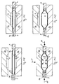
- FIG. 1 shows first in an overview of the steps for performing a hydroforming of a tubular workpiece 1.
- the workpiece 1 is inserted into the lower part 2a of a mold 2 and then the in FIG. 1a first raised upper mold 2b, as in FIG. 1 b lowered onto the lower mold 2a.
- the closed mold 2 has an inner contour 3, also called a form engraving, which defines the later outer shape of the formed workpiece 1.
- a sealing punch 4 and on the left side a punch 5 for filling and pressurization to the workpiece ends 1 a are employed in this example on the right side.
- the punch 5 has a channel 5a for this purpose.
- a closing pressure P is shown exerted in the vertical direction on the mold and also a respective contact pressure AP on the two punches 4/5. It is filled by the punch 5, the workpiece interior with liquid fluid and placed under high pressure, so that the workpiece wall expands until it rests against the inner contour 3. Then, the workpiece 1 is formed and can by opening the mold 2 and removing the punch 4/5, such as Figure 1d ) shows are taken.
- FIG. 2 clarifies the problem arising here.
- the molding tool 2 In the left-side section of the molding tool 2, the molding tool 2 can be seen in the closed and unloaded state with a view of a workpiece end 1a.
- the lateral end regions of the mold in this case have an opening cross section which corresponds to the outer cross section of a workpiece 1 to be inserted at the end region 1a.
- the same situation is in a loaded state, ie when a closing pressure P is exerted on the molding tool 2 from above via the molding tool part 2b.
- the parting plane TE between the two mold halves 2a and 2b moves downwards by the amount ⁇ . This can lead to a leak in the pressed stamps 4/5.
- FIG. 3 shows an overview of a device according to the invention.
- a lower mold part 2a is arranged via an intermediate piece or a support 7.
- the inner contour 3 of this lower part 2a can be seen.
- the drive plunger 10 which carries the upper mold part 2b and downwardly moves the closing pressure generated, which is held during the forming.
- the drive 8 then serves to open the forming tool 2.
- the drive ram 10 may be hydraulically driven or mechanically driven e.g. via a toggle mechanism.
- This frame or the frame serves to receive the process forces and forms a carrier for further essential device components. He can e.g. from screwed frame parts 9 or comprise a welded or cast construction.
- the essential core of the invention shows the FIG. 4 omitting the drive 8 and the frame 9.
- the invention extend through the mold 2 and its lower part 2a, two mutually parallel rods 11 which are embedded in the lower mold part 2a to half of their cross-section.
- the rods continue to extend parallel to the longitudinal axis of the mold, which is given by the orientation of the contour 3 and the insertable therein workpiece.
- the rods 11 may have a round cross-section in this example. It is also possible to use a cross section deviating from the round shape or to form a flat track guide.
- Both carriages 12 have two parallel bores through which the rods 11 pass. For example, can be pressed into the bores guide bushings, eg as plain bearings.
- the carriage 12 are in the FIGS. 1 arranged schematically stamp 4 and 5 or arranged generally means for sealing and filling / pressurizing. Also, the carriages in all possible embodiments can form the carriers for the fluid supply, wherein the fluid is forwarded by means of a carriage to the corresponding punch.
- the stamp 12 are adapted to the cross-sectional shape of the end portions 1 a of a workpiece to ensure a seal. Also, they may be conical or have a step shape, in particular to ensure a Nachschieben workpiece material during the forming.
- the carriages 12 can be moved by means of the drives 13 arranged on both sides in the direction of the arrow and with a contact pressure AP, the punches can be pressed against the open workpiece ends, which are not shown in this figure. Also, a Nachschiebekraft be exercised on the workpiece 1 via a punch 4.5 by the drives.
- the drives 13 are fastened to the base plate 6 via respective drive holders 14. Reaction forces of the drives are thus introduced into the base plate 6, as well as the closing force.
- the drives each move drive plungers 15 whose front active surfaces 15a press substantially free of lateral forces on a respective corresponding active surface 12a of a carriage 12.
- a direct loose contact may be provided or it may, for example, as shown in the detail drawing, the transverse force transmission reducing means 16 may be provided.
- Such a means is arranged between the active surfaces 15a and 12a, for example, as a roller bearing 16, which has a plurality of rollers 17 arranged one above the other horizontally and perpendicular to the direction of displacement of a carriage 12.
- the active surfaces 12a and 15a can thus slide parallel to one another, in particular vertically past one another, so that forces are only vertical be transferred between the active surfaces, but not in the vertical direction, ie not in the direction of the closing force in which it can lead to deformation of the mold. In the present case, decoupling in this direction is sufficient since a transverse force can occur substantially only in the vertical direction.
- the carriage and the stamp attached to maintain their relative position, in particular their coaxiality to the workpiece end, since they are moved over the arranged in the parting plane TE of the mold 2 guide 11 and on the other hand, that the downward movement of the parting plane TE by the decoupling in the vertical direction does not lead to a force effect between the drive 13 and slide 12, which has a vertical component to the thrust direction along the guide.
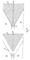
- the Figures 5 and 6 show two alternative forms of filling and pressurizing nozzle 5.
- the stub 5 has a tapered, in particular conical tip, as well as a central channel 5a opening into the tip.
- the situation before applying a contact pressure on a workpiece end 1 a to recognize which rests in the mold 2.
- the situation can be recognized by the application of a contact pressure.
- the workpiece end 1a is deformed, in particular widened, by the tip of the punch 5, as a result of which a particularly dense system results.
- the tip which has a more pointed conicity (smaller point angle), than the mold portion 2c around the workpiece end, it is achieved that the workpiece end between the front end of the tip and the conical mold portion 2c is clamped. This results in an optimal positive and / or non-positive tightness.
- FIG. 6 shows an alternative embodiment of the punch 5 or without channel 5a and the sealing punch 4.
- the punch 5 has a conical tip 5b as a contact surface to allow a better immersion in the workpiece end 1a.
- the front end of the punch is just like the end 1 a of the workpiece 1, executed at least once stepped.
- a step in the workpiece can be easily formed by the end face of the end.
- the ends of the workpiece and punch are here matched with respect to the two stages.
- a high pressure pressurized fluid pressure system may be used in known manner, e.g. be executed with pumps, filters, valves.
Landscapes
- Physics & Mathematics (AREA)
- Fluid Mechanics (AREA)
- Engineering & Computer Science (AREA)
- Mechanical Engineering (AREA)
- Shaping Metal By Deep-Drawing, Or The Like (AREA)
- Preparation Of Compounds By Using Micro-Organisms (AREA)
- Press Drives And Press Lines (AREA)
Claims (11)
- Dispositif de déformation, sous haute pression intérieure, de composants constitués de pièces d'oeuvre tubulaires, en particulier de microcomposants, comprenant un outil de formage au moins en deux parties, dans lequel une pièce d'oeuvre est susceptible d'être insérée, ainsi que des moyens pour isoler de manière étanche et/ou pour solliciter par une pression la pièce d'oeuvre sur les extrémités de pièce d'oeuvre, caractérisé en ce que, sur l'outil de formage (2a, 2b) est disposé au moins un guidage (11), sur lequel est déplaçable un chariot (12), portant des moyens (4, 5) pour isoler de manière étanche et/ou remplir/solliciter par une pression une extrémité de pièce d'oeuvre (1a), un chariot (12) étant déplaçable au moyen d'un dispositif d'entraînement (13, 15), disposé séparément par rapport à au moins un guidage (11), couplé, au moins sensiblement sans effort transversal, au chariot (12).
- Dispositif selon la revendication 1, caractérisé en ce que le au moins un guidage (11) est disposé sur au moins l'une des parties (2a) de l'outil de formage (2a, 2b).
- Dispositif selon l'une des revendications précédentes, caractérisé en ce qu'à chacune des extrémités de pièce d'oeuvre (1a) est associé un guidage (11) avec un chariot (12) et un dispositif d'entraînement (13, 15).
- Dispositif selon l'une des revendications précédentes, caractérisé en ce qu'un guidage (11) est disposé dans le plan de séparation (TE) de l'outil de formage (2, 2a, 2b).
- Dispositif selon l'une des revendications précédentes, caractérisé en ce qu'un guidage (11) s'étend à travers un outil de formage (2a, 2b), en particulier d'une extrémité d'outil (1a) à une autre extrémité d'outil (1a).
- Dispositif selon l'une des revendications précédentes, caractérisé en ce qu'un guidage est formé par deux barres (11), parallèles au moins à l'extérieur de l'outil de formage (2, 2a, 2b), en particulier entourées par un chariot (12).
- Dispositif selon l'une des revendications précédentes, caractérisé en ce qu'un dispositif d'entraînement (13, 15), ou au moins un support (14) d'un dispositif d'entraînement (13, 15), avec une partie, en particulier une partie inférieure (2a) de l'outil de formage (2), est disposé sur une plaque de base (6) commune, en particulier une pression de fermeture (P) est appliquée sur une partie supérieure (2b) de l'outil de formage (2).
- Dispositif selon la revendication 7, caractérisé en ce que la pression de fermeture (P) est appliquée au moyen d'un dispositif d'entraînement (8, 10), relié à la plaque de base (6) commune par l'intermédiaire d'un agencement bâti/cadre (9).
- Dispositif selon l'une des revendications précédentes, caractérisé en ce que le couplage, sensiblement sans effort transversal, entre un dispositif d'entraînement (13, 15) et un chariot (12), est réalisé au moyen d'un contact lâche entre un chariot (12) et dispositif d'entraînement (13, 15).
- Dispositif selon la revendication 9, caractérisé en ce que des moyens (16, 17), réduisant l'effort transversal et/ou le frottement, sont utilisés dans la zone du contact lâche.
- Dispositif selon la revendication 10, caractérisé en ce que les moyens (16) sont réalisés sous forme de montage en paliers à rouleaux (17) et/ou à billes, les rouleaux (17), dans le cas d'une force de fermeture (P) verticale, étant en particulier disposés horizontalement et perpendiculairement au déplacement du chariot, entre les faces de contact (15a, 12a) respectives du dispositif d'entraînement (13, 15) et du chariot (12).
Applications Claiming Priority (2)
| Application Number | Priority Date | Filing Date | Title |
|---|---|---|---|
| DE102006047017A DE102006047017A1 (de) | 2006-10-02 | 2006-10-02 | Vorrichtung zur Innenhochdruckumformung |
| PCT/EP2007/008459 WO2008040497A1 (fr) | 2006-10-02 | 2007-09-28 | Dispositif de déformation sous haute pression intérieure |
Publications (2)
| Publication Number | Publication Date |
|---|---|
| EP2076342A1 EP2076342A1 (fr) | 2009-07-08 |
| EP2076342B1 true EP2076342B1 (fr) | 2012-02-08 |
Family
ID=38969567
Family Applications (1)
| Application Number | Title | Priority Date | Filing Date |
|---|---|---|---|
| EP07818541A Not-in-force EP2076342B1 (fr) | 2006-10-02 | 2007-09-28 | Dispositif de déformation sous haute pression intérieure |
Country Status (5)
| Country | Link |
|---|---|
| US (1) | US7946146B2 (fr) |
| EP (1) | EP2076342B1 (fr) |
| AT (1) | ATE544539T1 (fr) |
| DE (1) | DE102006047017A1 (fr) |
| WO (1) | WO2008040497A1 (fr) |
Families Citing this family (5)
| Publication number | Priority date | Publication date | Assignee | Title |
|---|---|---|---|---|
| CN103313808B (zh) * | 2011-01-24 | 2015-09-09 | Posco公司 | 使用液压成型来制造大口径产品的装置和方法 |
| US10480544B2 (en) * | 2016-04-19 | 2019-11-19 | The Boeing Company | Bladder assembly and associated bore alignment system and method |
| CN111872212B (zh) * | 2020-07-27 | 2022-05-17 | 佛山市永恒液压机械有限公司 | 一种管材密封方法 |
| CN114798815B (zh) * | 2022-06-06 | 2023-08-22 | 哈尔滨工业大学(威海) | 一种零件校形模具 |
| CN117299981A (zh) * | 2023-11-23 | 2023-12-29 | 江苏华裕机电科技有限公司 | 一种用于电动车车把生产的涨管设备 |
Family Cites Families (14)
| Publication number | Priority date | Publication date | Assignee | Title |
|---|---|---|---|---|
| US1501023A (en) * | 1920-08-25 | 1924-07-08 | Gen Motors Corp | Process and apparatus for forming metal objects |
| FR847257A (fr) * | 1937-12-11 | 1939-10-05 | Procédé pour fabriquer des viroles d'une seule pièce pour fûts métalliques biconiques | |
| US5233854A (en) * | 1992-05-11 | 1993-08-10 | General Motors Corporation | Press apparatus for hydroforming a tube |
| DE19751408C2 (de) | 1997-11-14 | 1999-10-21 | Mannesmann Ag | Verfahren und Vorrichtung zur Herstellung eines Integralgehäuses für Hydrolenkung |
| ATE257752T1 (de) | 2000-05-13 | 2004-01-15 | Interforge Klee Gmbh | Verfahren und vorrichtung zur hochdruckumformung |
| DE10058521A1 (de) * | 2000-11-24 | 2002-05-29 | Interforge Klee Gmbh | Verfahren und Vorrichtung zum Weiten von zylindrischen Hohlkörpern |
| DE10056610A1 (de) * | 2000-11-15 | 2002-05-23 | Schuler Hydroforming Gmbh & Co | Vorrichtung zur Innenhochdruck-Umformung von Hohlkörpern |
| JP2004276077A (ja) * | 2003-03-17 | 2004-10-07 | Nsk Ltd | ハイドロフォーミング装置及び方法 |
| KR100616750B1 (ko) * | 2004-02-24 | 2006-08-28 | 주식회사 성우하이텍 | 온간 액압 성형 장치 |
| DE102004017235B4 (de) * | 2004-04-05 | 2006-03-30 | Forschungsgesellschaft Umformtechnik Mbh | Werkzeug zum Innenhochdruckumformen insbesondere rohrförmiger Werkstücke |
| JP2006122943A (ja) * | 2004-10-28 | 2006-05-18 | Nissan Motor Co Ltd | 液圧成形用ノズルおよび液圧成形装置 |
| US7392679B1 (en) * | 2007-02-13 | 2008-07-01 | Gm Global Technology Operations, Inc. | Hydroform tube sealing assembly |
| US7380429B1 (en) * | 2007-02-28 | 2008-06-03 | Gm Global Technology Operations, Inc. | Tubular local expansion apparatus and method of locally expanding tubular member for vehicles |
| US7685856B1 (en) * | 2008-11-11 | 2010-03-30 | Gm Global Technology Operations, Inc. | Two mode hydroform seal apparatus and method |
-
2006
- 2006-10-02 DE DE102006047017A patent/DE102006047017A1/de not_active Withdrawn
-
2007
- 2007-09-28 AT AT07818541T patent/ATE544539T1/de active
- 2007-09-28 EP EP07818541A patent/EP2076342B1/fr not_active Not-in-force
- 2007-09-28 US US12/443,718 patent/US7946146B2/en not_active Expired - Fee Related
- 2007-09-28 WO PCT/EP2007/008459 patent/WO2008040497A1/fr not_active Ceased
Also Published As
| Publication number | Publication date |
|---|---|
| DE102006047017A8 (de) | 2008-09-04 |
| ATE544539T1 (de) | 2012-02-15 |
| US20090320543A1 (en) | 2009-12-31 |
| EP2076342A1 (fr) | 2009-07-08 |
| US7946146B2 (en) | 2011-05-24 |
| DE102006047017A1 (de) | 2008-04-03 |
| WO2008040497A1 (fr) | 2008-04-10 |
Similar Documents
| Publication | Publication Date | Title |
|---|---|---|
| DE69010429T2 (de) | Vorrichtung und Verfahren zum Formen eines rohrförmigen Rahmens. | |
| EP2062987B1 (fr) | Presse de moulage à chaud | |
| EP2076342B1 (fr) | Dispositif de déformation sous haute pression intérieure | |
| DE19833006B4 (de) | Verfahren und Vorrichtung zur Herstellung rohrförmiger gebogener Hohlkörper durch Innenhochdruckumformen | |
| DE69524438T2 (de) | Füll- und druckaufschlagseinrichtung | |
| CH385146A (de) | Verfahren und Vorrichtung zur kalten Formung von Hohlprofilkörpern | |
| DE10056610A1 (de) | Vorrichtung zur Innenhochdruck-Umformung von Hohlkörpern | |
| EP2036628B1 (fr) | Procédé et dispositif de fabrication d'une pièce à usiner comprenant des courbures à l'aide d'un fluide sous pression | |
| EP2364792B1 (fr) | Dispositif de formage | |
| EP3115171B1 (fr) | Moule a mousse comprenant un element d'extremite d'etancheite deplaçable | |
| DE19814487A1 (de) | Schließvorrichtung für Ur- und Umformwerkzeuge | |
| DE19956506A1 (de) | Vorrichtung zum Tiefziehen von becherförmigen Körpern | |
| DE10065033C1 (de) | Verfahren zur Herstellung eines umfänglich geschlossenen Hohlprofiles und eine Vorrichtung zur Durchführung desselben | |
| EP0865845A1 (fr) | Procédé pour maintenir ensemble moules ou matrices en deux parties soumises à pression interne et dispositif pour la mise en oeuvre du procédé | |
| DE10048005A1 (de) | Vorrichtung zum Verbinden mindestens zweier flächiger, übereinander liegender Bauteile | |
| DE10343868B3 (de) | Innenhochdruckumformanlage | |
| EP0760264A1 (fr) | Dispositif pour le formage hydraulique des pièces tubulaires | |
| DE10358493B4 (de) | Vorrichtung zum Innenhochdruckumformen | |
| DE10030792C2 (de) | Mehrstufenpresse, insbesondere Quertransportpresse, mit hydraulischer Schließvorrichtung | |
| DE10230071C1 (de) | Zuhaltevorrichtung | |
| DE7721553U1 (de) | Hydraulische rohrendenstauchpresse | |
| DE102012016344B4 (de) | Vorrichtung und Verfahren, insbesondere zum isostatischen Pressen oder zum Druckgießen | |
| EP1657007B9 (fr) | Procédé de formage de pièces | |
| DE19907018A1 (de) | Verfahren zum Verformen von Hohlkörpern aus Metall | |
| DE19719628A1 (de) | Verfahren und Einrichtung zur Herstellung von ausgebauchten Hohlprofilen |
Legal Events
| Date | Code | Title | Description |
|---|---|---|---|
| PUAI | Public reference made under article 153(3) epc to a published international application that has entered the european phase |
Free format text: ORIGINAL CODE: 0009012 |
|
| 17P | Request for examination filed |
Effective date: 20090429 |
|
| AK | Designated contracting states |
Kind code of ref document: A1 Designated state(s): AT BE BG CH CY CZ DE DK EE ES FI FR GB GR HU IE IS IT LI LT LU LV MC MT NL PL PT RO SE SI SK TR |
|
| REG | Reference to a national code |
Ref country code: DE Ref legal event code: R079 Ref document number: 502007009261 Country of ref document: DE Free format text: PREVIOUS MAIN CLASS: B21D0026020000 Ipc: B21D0026045000 |
|
| GRAP | Despatch of communication of intention to grant a patent |
Free format text: ORIGINAL CODE: EPIDOSNIGR1 |
|
| RIC1 | Information provided on ipc code assigned before grant |
Ipc: B21D 26/045 20110101AFI20110831BHEP |
|
| DAX | Request for extension of the european patent (deleted) | ||
| GRAS | Grant fee paid |
Free format text: ORIGINAL CODE: EPIDOSNIGR3 |
|
| GRAA | (expected) grant |
Free format text: ORIGINAL CODE: 0009210 |
|
| RAP1 | Party data changed (applicant data changed or rights of an application transferred) |
Owner name: FACHHOCHSCHULE KOELN |
|
| AK | Designated contracting states |
Kind code of ref document: B1 Designated state(s): AT BE BG CH CY CZ DE DK EE ES FI FR GB GR HU IE IS IT LI LT LU LV MC MT NL PL PT RO SE SI SK TR |
|
| REG | Reference to a national code |
Ref country code: GB Ref legal event code: FG4D Free format text: NOT ENGLISH |
|
| REG | Reference to a national code |
Ref country code: AT Ref legal event code: REF Ref document number: 544539 Country of ref document: AT Kind code of ref document: T Effective date: 20120215 Ref country code: CH Ref legal event code: EP |
|
| REG | Reference to a national code |
Ref country code: CH Ref legal event code: NV Representative=s name: SCHMAUDER & PARTNER AG PATENT- UND MARKENANWAELTE |
|
| REG | Reference to a national code |
Ref country code: DE Ref legal event code: R096 Ref document number: 502007009261 Country of ref document: DE Effective date: 20120405 |
|
| REG | Reference to a national code |
Ref country code: NL Ref legal event code: VDEP Effective date: 20120208 |
|
| LTIE | Lt: invalidation of european patent or patent extension |
Effective date: 20120208 |
|
| PG25 | Lapsed in a contracting state [announced via postgrant information from national office to epo] |
Ref country code: NL Free format text: LAPSE BECAUSE OF FAILURE TO SUBMIT A TRANSLATION OF THE DESCRIPTION OR TO PAY THE FEE WITHIN THE PRESCRIBED TIME-LIMIT Effective date: 20120208 Ref country code: LT Free format text: LAPSE BECAUSE OF FAILURE TO SUBMIT A TRANSLATION OF THE DESCRIPTION OR TO PAY THE FEE WITHIN THE PRESCRIBED TIME-LIMIT Effective date: 20120208 Ref country code: IS Free format text: LAPSE BECAUSE OF FAILURE TO SUBMIT A TRANSLATION OF THE DESCRIPTION OR TO PAY THE FEE WITHIN THE PRESCRIBED TIME-LIMIT Effective date: 20120608 |
|
| REG | Reference to a national code |
Ref country code: IE Ref legal event code: FD4D |
|
| PG25 | Lapsed in a contracting state [announced via postgrant information from national office to epo] |
Ref country code: FI Free format text: LAPSE BECAUSE OF FAILURE TO SUBMIT A TRANSLATION OF THE DESCRIPTION OR TO PAY THE FEE WITHIN THE PRESCRIBED TIME-LIMIT Effective date: 20120208 Ref country code: GR Free format text: LAPSE BECAUSE OF FAILURE TO SUBMIT A TRANSLATION OF THE DESCRIPTION OR TO PAY THE FEE WITHIN THE PRESCRIBED TIME-LIMIT Effective date: 20120509 Ref country code: LV Free format text: LAPSE BECAUSE OF FAILURE TO SUBMIT A TRANSLATION OF THE DESCRIPTION OR TO PAY THE FEE WITHIN THE PRESCRIBED TIME-LIMIT Effective date: 20120208 Ref country code: PL Free format text: LAPSE BECAUSE OF FAILURE TO SUBMIT A TRANSLATION OF THE DESCRIPTION OR TO PAY THE FEE WITHIN THE PRESCRIBED TIME-LIMIT Effective date: 20120208 Ref country code: PT Free format text: LAPSE BECAUSE OF FAILURE TO SUBMIT A TRANSLATION OF THE DESCRIPTION OR TO PAY THE FEE WITHIN THE PRESCRIBED TIME-LIMIT Effective date: 20120608 |
|
| PG25 | Lapsed in a contracting state [announced via postgrant information from national office to epo] |
Ref country code: CY Free format text: LAPSE BECAUSE OF FAILURE TO SUBMIT A TRANSLATION OF THE DESCRIPTION OR TO PAY THE FEE WITHIN THE PRESCRIBED TIME-LIMIT Effective date: 20120208 |
|
| PG25 | Lapsed in a contracting state [announced via postgrant information from national office to epo] |
Ref country code: IE Free format text: LAPSE BECAUSE OF FAILURE TO SUBMIT A TRANSLATION OF THE DESCRIPTION OR TO PAY THE FEE WITHIN THE PRESCRIBED TIME-LIMIT Effective date: 20120208 Ref country code: DK Free format text: LAPSE BECAUSE OF FAILURE TO SUBMIT A TRANSLATION OF THE DESCRIPTION OR TO PAY THE FEE WITHIN THE PRESCRIBED TIME-LIMIT Effective date: 20120208 Ref country code: RO Free format text: LAPSE BECAUSE OF FAILURE TO SUBMIT A TRANSLATION OF THE DESCRIPTION OR TO PAY THE FEE WITHIN THE PRESCRIBED TIME-LIMIT Effective date: 20120208 Ref country code: CZ Free format text: LAPSE BECAUSE OF FAILURE TO SUBMIT A TRANSLATION OF THE DESCRIPTION OR TO PAY THE FEE WITHIN THE PRESCRIBED TIME-LIMIT Effective date: 20120208 Ref country code: SI Free format text: LAPSE BECAUSE OF FAILURE TO SUBMIT A TRANSLATION OF THE DESCRIPTION OR TO PAY THE FEE WITHIN THE PRESCRIBED TIME-LIMIT Effective date: 20120208 Ref country code: EE Free format text: LAPSE BECAUSE OF FAILURE TO SUBMIT A TRANSLATION OF THE DESCRIPTION OR TO PAY THE FEE WITHIN THE PRESCRIBED TIME-LIMIT Effective date: 20120208 Ref country code: SE Free format text: LAPSE BECAUSE OF FAILURE TO SUBMIT A TRANSLATION OF THE DESCRIPTION OR TO PAY THE FEE WITHIN THE PRESCRIBED TIME-LIMIT Effective date: 20120208 |
|
| PG25 | Lapsed in a contracting state [announced via postgrant information from national office to epo] |
Ref country code: SK Free format text: LAPSE BECAUSE OF FAILURE TO SUBMIT A TRANSLATION OF THE DESCRIPTION OR TO PAY THE FEE WITHIN THE PRESCRIBED TIME-LIMIT Effective date: 20120208 Ref country code: IT Free format text: LAPSE BECAUSE OF FAILURE TO SUBMIT A TRANSLATION OF THE DESCRIPTION OR TO PAY THE FEE WITHIN THE PRESCRIBED TIME-LIMIT Effective date: 20120208 |
|
| PLBE | No opposition filed within time limit |
Free format text: ORIGINAL CODE: 0009261 |
|
| STAA | Information on the status of an ep patent application or granted ep patent |
Free format text: STATUS: NO OPPOSITION FILED WITHIN TIME LIMIT |
|
| 26N | No opposition filed |
Effective date: 20121109 |
|
| REG | Reference to a national code |
Ref country code: DE Ref legal event code: R097 Ref document number: 502007009261 Country of ref document: DE Effective date: 20121109 |
|
| BERE | Be: lapsed |
Owner name: FACHHOCHSCHULE KOLN Effective date: 20120930 |
|
| PG25 | Lapsed in a contracting state [announced via postgrant information from national office to epo] |
Ref country code: MC Free format text: LAPSE BECAUSE OF NON-PAYMENT OF DUE FEES Effective date: 20120930 Ref country code: ES Free format text: LAPSE BECAUSE OF FAILURE TO SUBMIT A TRANSLATION OF THE DESCRIPTION OR TO PAY THE FEE WITHIN THE PRESCRIBED TIME-LIMIT Effective date: 20120519 |
|
| PG25 | Lapsed in a contracting state [announced via postgrant information from national office to epo] |
Ref country code: BG Free format text: LAPSE BECAUSE OF FAILURE TO SUBMIT A TRANSLATION OF THE DESCRIPTION OR TO PAY THE FEE WITHIN THE PRESCRIBED TIME-LIMIT Effective date: 20120508 Ref country code: BE Free format text: LAPSE BECAUSE OF NON-PAYMENT OF DUE FEES Effective date: 20120930 |
|
| REG | Reference to a national code |
Ref country code: AT Ref legal event code: MM01 Ref document number: 544539 Country of ref document: AT Kind code of ref document: T Effective date: 20120928 |
|
| PG25 | Lapsed in a contracting state [announced via postgrant information from national office to epo] |
Ref country code: MT Free format text: LAPSE BECAUSE OF FAILURE TO SUBMIT A TRANSLATION OF THE DESCRIPTION OR TO PAY THE FEE WITHIN THE PRESCRIBED TIME-LIMIT Effective date: 20120208 |
|
| PG25 | Lapsed in a contracting state [announced via postgrant information from national office to epo] |
Ref country code: AT Free format text: LAPSE BECAUSE OF NON-PAYMENT OF DUE FEES Effective date: 20120928 |
|
| PG25 | Lapsed in a contracting state [announced via postgrant information from national office to epo] |
Ref country code: TR Free format text: LAPSE BECAUSE OF FAILURE TO SUBMIT A TRANSLATION OF THE DESCRIPTION OR TO PAY THE FEE WITHIN THE PRESCRIBED TIME-LIMIT Effective date: 20120208 |
|
| PG25 | Lapsed in a contracting state [announced via postgrant information from national office to epo] |
Ref country code: LU Free format text: LAPSE BECAUSE OF NON-PAYMENT OF DUE FEES Effective date: 20120928 |
|
| PG25 | Lapsed in a contracting state [announced via postgrant information from national office to epo] |
Ref country code: HU Free format text: LAPSE BECAUSE OF FAILURE TO SUBMIT A TRANSLATION OF THE DESCRIPTION OR TO PAY THE FEE WITHIN THE PRESCRIBED TIME-LIMIT Effective date: 20070928 |
|
| REG | Reference to a national code |
Ref country code: FR Ref legal event code: PLFP Year of fee payment: 10 |
|
| REG | Reference to a national code |
Ref country code: FR Ref legal event code: PLFP Year of fee payment: 11 |
|
| PGFP | Annual fee paid to national office [announced via postgrant information from national office to epo] |
Ref country code: GB Payment date: 20170927 Year of fee payment: 11 Ref country code: CH Payment date: 20170912 Year of fee payment: 11 Ref country code: FR Payment date: 20170829 Year of fee payment: 11 Ref country code: DE Payment date: 20170920 Year of fee payment: 11 |
|
| REG | Reference to a national code |
Ref country code: DE Ref legal event code: R119 Ref document number: 502007009261 Country of ref document: DE |
|
| REG | Reference to a national code |
Ref country code: CH Ref legal event code: PL |
|
| GBPC | Gb: european patent ceased through non-payment of renewal fee |
Effective date: 20180928 |
|
| PG25 | Lapsed in a contracting state [announced via postgrant information from national office to epo] |
Ref country code: DE Free format text: LAPSE BECAUSE OF NON-PAYMENT OF DUE FEES Effective date: 20190402 |
|
| PG25 | Lapsed in a contracting state [announced via postgrant information from national office to epo] |
Ref country code: LI Free format text: LAPSE BECAUSE OF NON-PAYMENT OF DUE FEES Effective date: 20180930 Ref country code: CH Free format text: LAPSE BECAUSE OF NON-PAYMENT OF DUE FEES Effective date: 20180930 Ref country code: FR Free format text: LAPSE BECAUSE OF NON-PAYMENT OF DUE FEES Effective date: 20180930 |
|
| PG25 | Lapsed in a contracting state [announced via postgrant information from national office to epo] |
Ref country code: GB Free format text: LAPSE BECAUSE OF NON-PAYMENT OF DUE FEES Effective date: 20180928 |