EP2036680A2 - Machine-outil manuelle dotée d'un mécanisme de percussion à ressort pneumatique, moteur linéaire et procédé de commande - Google Patents
Machine-outil manuelle dotée d'un mécanisme de percussion à ressort pneumatique, moteur linéaire et procédé de commande Download PDFInfo
- Publication number
- EP2036680A2 EP2036680A2 EP08105156A EP08105156A EP2036680A2 EP 2036680 A2 EP2036680 A2 EP 2036680A2 EP 08105156 A EP08105156 A EP 08105156A EP 08105156 A EP08105156 A EP 08105156A EP 2036680 A2 EP2036680 A2 EP 2036680A2
- Authority
- EP
- European Patent Office
- Prior art keywords
- rotor
- control method
- piston
- hand tool
- linear motor
- Prior art date
- Legal status (The legal status is an assumption and is not a legal conclusion. Google has not performed a legal analysis and makes no representation as to the accuracy of the status listed.)
- Withdrawn
Links
- 238000009527 percussion Methods 0.000 title claims abstract description 32
- 238000000034 method Methods 0.000 title claims description 32
- 230000007246 mechanism Effects 0.000 title claims description 10
- 230000033001 locomotion Effects 0.000 claims description 37
- 238000004364 calculation method Methods 0.000 claims description 16
- 230000007704 transition Effects 0.000 claims description 12
- 230000005284 excitation Effects 0.000 claims description 7
- 230000001953 sensory effect Effects 0.000 claims description 7
- 238000013459 approach Methods 0.000 claims description 5
- 238000009423 ventilation Methods 0.000 claims description 5
- 238000006073 displacement reaction Methods 0.000 claims description 4
- 230000003111 delayed effect Effects 0.000 claims description 3
- 229920001971 elastomer Polymers 0.000 claims description 3
- 239000000806 elastomer Substances 0.000 claims description 3
- 230000001133 acceleration Effects 0.000 claims description 2
- 230000015572 biosynthetic process Effects 0.000 claims description 2
- 230000001404 mediated effect Effects 0.000 claims description 2
- 230000008569 process Effects 0.000 description 9
- 238000005259 measurement Methods 0.000 description 8
- 230000001276 controlling effect Effects 0.000 description 5
- 238000003491 array Methods 0.000 description 4
- 238000010009 beating Methods 0.000 description 3
- 238000010168 coupling process Methods 0.000 description 2
- 229920002379 silicone rubber Polymers 0.000 description 2
- 239000004945 silicone rubber Substances 0.000 description 2
- 230000004888 barrier function Effects 0.000 description 1
- 238000007664 blowing Methods 0.000 description 1
- 230000008859 change Effects 0.000 description 1
- 230000008878 coupling Effects 0.000 description 1
- 238000005859 coupling reaction Methods 0.000 description 1
- 238000013016 damping Methods 0.000 description 1
- 230000001419 dependent effect Effects 0.000 description 1
- 238000001514 detection method Methods 0.000 description 1
- 238000011161 development Methods 0.000 description 1
- 230000018109 developmental process Effects 0.000 description 1
- 238000010586 diagram Methods 0.000 description 1
- 230000006870 function Effects 0.000 description 1
- 238000009434 installation Methods 0.000 description 1
- 230000003993 interaction Effects 0.000 description 1
- 230000001105 regulatory effect Effects 0.000 description 1
- 230000000717 retained effect Effects 0.000 description 1
- 238000013022 venting Methods 0.000 description 1
Images

Classifications
-
- B—PERFORMING OPERATIONS; TRANSPORTING
- B25—HAND TOOLS; PORTABLE POWER-DRIVEN TOOLS; MANIPULATORS
- B25D—PERCUSSIVE TOOLS
- B25D11/00—Portable percussive tools with electromotor or other motor drive
- B25D11/06—Means for driving the impulse member
- B25D11/064—Means for driving the impulse member using an electromagnetic drive
-
- B—PERFORMING OPERATIONS; TRANSPORTING
- B25—HAND TOOLS; PORTABLE POWER-DRIVEN TOOLS; MANIPULATORS
- B25D—PERCUSSIVE TOOLS
- B25D11/00—Portable percussive tools with electromotor or other motor drive
- B25D11/005—Arrangements for adjusting the stroke of the impulse member or for stopping the impact action when the tool is lifted from the working surface
-
- H—ELECTRICITY
- H02—GENERATION; CONVERSION OR DISTRIBUTION OF ELECTRIC POWER
- H02K—DYNAMO-ELECTRIC MACHINES
- H02K11/00—Structural association of dynamo-electric machines with electric components or with devices for shielding, monitoring or protection
- H02K11/30—Structural association with control circuits or drive circuits
- H02K11/33—Drive circuits, e.g. power electronics
-
- H—ELECTRICITY
- H02—GENERATION; CONVERSION OR DISTRIBUTION OF ELECTRIC POWER
- H02K—DYNAMO-ELECTRIC MACHINES
- H02K33/00—Motors with reciprocating, oscillating or vibrating magnet, armature or coil system
- H02K33/16—Motors with reciprocating, oscillating or vibrating magnet, armature or coil system with polarised armatures moving in alternate directions by reversal or energisation of a single coil system
-
- H—ELECTRICITY
- H02—GENERATION; CONVERSION OR DISTRIBUTION OF ELECTRIC POWER
- H02P—CONTROL OR REGULATION OF ELECTRIC MOTORS, ELECTRIC GENERATORS OR DYNAMO-ELECTRIC CONVERTERS; CONTROLLING TRANSFORMERS, REACTORS OR CHOKE COILS
- H02P25/00—Arrangements or methods for the control of AC motors characterised by the kind of AC motor or by structural details
- H02P25/02—Arrangements or methods for the control of AC motors characterised by the kind of AC motor or by structural details characterised by the kind of motor
- H02P25/06—Linear motors
-
- B—PERFORMING OPERATIONS; TRANSPORTING
- B25—HAND TOOLS; PORTABLE POWER-DRIVEN TOOLS; MANIPULATORS
- B25D—PERCUSSIVE TOOLS
- B25D2250/00—General details of portable percussive tools; Components used in portable percussive tools
- B25D2250/035—Bleeding holes, e.g. in piston guide-sleeves
-
- B—PERFORMING OPERATIONS; TRANSPORTING
- B25—HAND TOOLS; PORTABLE POWER-DRIVEN TOOLS; MANIPULATORS
- B25D—PERCUSSIVE TOOLS
- B25D2250/00—General details of portable percussive tools; Components used in portable percussive tools
- B25D2250/221—Sensors
-
- H—ELECTRICITY
- H01—ELECTRIC ELEMENTS
- H01F—MAGNETS; INDUCTANCES; TRANSFORMERS; SELECTION OF MATERIALS FOR THEIR MAGNETIC PROPERTIES
- H01F7/00—Magnets
- H01F7/06—Electromagnets; Actuators including electromagnets
- H01F7/08—Electromagnets; Actuators including electromagnets with armatures
- H01F7/18—Circuit arrangements for obtaining desired operating characteristics, e.g. for slow operation, for sequential energisation of windings, for high-speed energisation of windings
- H01F7/1844—Monitoring or fail-safe circuits
-
- H—ELECTRICITY
- H02—GENERATION; CONVERSION OR DISTRIBUTION OF ELECTRIC POWER
- H02K—DYNAMO-ELECTRIC MACHINES
- H02K7/00—Arrangements for handling mechanical energy structurally associated with dynamo-electric machines, e.g. structural association with mechanical driving motors or auxiliary dynamo-electric machines
- H02K7/14—Structural association with mechanical loads, e.g. with hand-held machine tools or fans
- H02K7/145—Hand-held machine tool
Definitions
- the invention refers to a hand tool machine with an air spring impact mechanism, which is driven by a linear motor, such as a hammer drill or chisel hammer, and an associated control method.
- a linear motor such as a hammer drill or chisel hammer
- the soft magnetic rotor of the controlled linear motor is designed as an exciter piston of a percussion piston coupled via an air spring.
- the air spring striking mechanism can be stopped electrically when lifting the tool from the workpiece, without the need for a controlled by the displacement of the tool Leertschweg the percussion piston is necessary, which mechanically opens the relatively wide ventilation openings to the air spring.
- a holding coil is necessary in addition to the exciting coil.
- the reference position may be identical to the empty position.
- the rotor could be magnetically fixed to a reference position by a holding coil in the state swung out (by friction damping) over several movement periods, the kinetic high-energy rotor could not be fixed in the same movement period due to the inertia. Thus, even with the use of an additional holding coil, the problem still exists of the lack of mechanically impressed positive guidance of the rotor or of the points of rotation not positioned at the same location.
- the object of the invention is the implementation of a hand tool with a pneumatic spring impact mechanism, which is driven by a linear motor, and an associated control method, which is robust under practice-relevant operating conditions.
- a hand tool with a linear motor on a runner which is limited axially movable axially between two inflection points along a striking axis and over which a percussion piston imparted via an air spring is driven, designed for IstSullivansbetician of the rotor sensors are connected to a computing means, via a Power electronics is connected to at least one excitation coil of the linear motor, wherein the rotor is displaceable in at least one turning point against a contact element and electromagnetically against these pressed.
- the inflection point (and corresponding to the associated system) of the rotor arranged in a start position, which is outside the power gap position in which the motor force on the rotor is zero even when the excitation coil is energized, advantageously further offset by slightly less than a quarter of the pole pitch thereof.
- the starting position of the rotor is also a detent position in which the latching force on the rotor is not equal to zero when the field coil is deenergized and the rotor presses against the contact element, whereby the rotor is reliably held against the contact element even when the field coil is de-energized.
- the aircraft piston near front landing element for the runner is present, whereby impermissible positions are avoided.
- the systems consist of a crosslinked elastomer, further advantageously of silicone rubber, whereby they are high temperature resistant and fatigue.
- a mechanical latching mechanism which is controllably connected to the computing means, for the at the stator near the rear landing element held runner present, whereby the position of the rotor is fixed without current when the linear motor is switched off.
- the guide tube has a narrow puff hole, which ensures a (over the period of motion) averaged constant volume of air in the air spring.
- At least one relatively large vent opening offset on the tool side which is always closed by the percussion piston in stable impact mode, but the tool offset tool (when the tool is lifted far from the workpiece) by tool displacement of the percussion piston in a Leerschlag too the air spring open is, whereby a stopping of the impact mechanism takes place when the tool is far off the workpiece.
- the ventilation opening for venting the air spring can only be closed internally via the flying piston (passive) or additionally externally via an adjustable control sleeve (active).
- an energizing step with the calculating means calculates (predetermined or calculated) data of a desired kinematic motion state S (x (t + [delta] t), v (t + [delta] t), a (t + [delta] t)) of the rotor at the time t + [delta] t the current required for its achievement of the exciting coil (s) and energized these via the power electronics.
- the computer uses stored integrated motor models for the motor characteristic or accesses stored in the memory measurement data arrays of the motor characteristic and interpolates them.
- the energizing step comprises a pole phase calculation which calculates the pole phase within the pole pitch from the position of the rotor, whereby the periodicity of the motor characteristic curve can be used in the calculation of the energization is and the motor models or measurement data arrays reduced.
- the acceleration in each case with constant motor force by the energizing coils are energized in the energizing step with constant magnitude constant current, whereby a high surge frequency is achieved.
- alternating currents produce only low heat losses in the power electronics and only need two highly loadable potentials.
- the delay step is preceded by a calculation step which calculates a delay time point at which the deceleration step starts with the calculating means from sensor-recorded data of the actual kinematic state of motion l (x (t), v (t), a (t)) of the rotor Delay step (only) over the time t is controllable as a parameter.
- the calculated delay time ensures that the runner turns at a given front inflection point.
- the computing means uses stored integrated calculation models for the deceleration process or accesses measurement data arrays of the deceleration process stored in the memory and interpolates them.
- the rotor is approximated in the investment step to the rear contact element and temporarily held there electromagnetically, whereby the percussion piston is already sucked into the starting position for the next blow.
- the rotor exceeds a critical speed or kinetic energy at a given location or cycle time.
- the runner exceeds a critical path absolutely or for a given cycle time.
- the percussion piston exceeds a critical path absolutely or for a given cycle time.
- the air spring falls below a critical pressure for a given cycle time.
- the impact mechanism drops below a critical input energy, which can be calculated when the motor voltage or the motor current and the rotor speed or the force acting on the rotor (for example by estimation via motor current) are known.
- the longer than a period the stable impact operation is and further advantageously shorter than ten period duration, followed by a holding step, whereby the superfluous air in the air spring is blown over the puff hole.
- Blowhole is ventilated. Conversely, a transition to the mechanical disengagement of the rotor is performed first at the transition from the idle mode.
- the application step comprises a braking step with (the movement) decelerating engine power, in which the runner is gently approached to the contact element, and a time later holding step with (the movement) accelerating engine power, in which the runner is temporarily held there, whereby both Steps are separately controllable.
- the braking step is preceded by a calculation step which calculates, from the sensor, data of the kinematic actual movement state (x (t), v (t), a (t)) of the rotor with the computing means, a braking time at which the braking step starts, whereby the braking operation (only) over time t is controllable as a parameter.
- the calculated braking time ensures that the runner gently hits the contact element only at a low ( ⁇ 2 m / s) final speed.
- the computing means uses stored integrated calculation models for the braking process or accesses measurement data arrays of the braking process stored in the memory and interpolates them.
- the speed and the position of the kinematic IstschulsSullivans the rotor as a variable of the calculation step sensory detected.
- derived quantities such as energy etc. are also possible.
- it is, for example, sufficient to detect the passage time of the rotor with two axially offset sensors.
- suitable sensor arrangements are possible.
- the braking step advantageously includes a force control loop for controlling the engine power required for a uniform approach speed (to the installation), whereby the increased friction values can be compensated for in the braking step, in particular for a still cold hand tool.
- a force control loop for controlling the engine power required for a uniform approach speed (to the installation), whereby the increased friction values can be compensated for in the braking step, in particular for a still cold hand tool.
- it is, for example, sufficient to detect a plurality of passage times of the rotor with an axial sensor array positioned close to the contact element.
- suitable sensor arrangements are possible.
- the holding step is preceded by a trigger step, which calculates a trigger condition for the holding time from sensor-recorded data of the kinematic actual movement state (x (t), v (t), a (t)) of the runner with the computing means, at which the holding step begins. whereby the holding process (only) over time t is controllable as a parameter.
- a speed limit and / or a position limit of the kinematic actual movement state of the runner are sensed.
- derived quantities such as energy etc. are also possible.
- it is, for example, sufficient to detect the passage time of the runner with a sensor positioned close to the contact element.
- suitable sensor arrangements are possible.
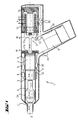
- a hand tool machine 1 striking along a striking axis A has a linear motor 2 with at least one exciter coil 10 whose axially movable runner 3 is driven by an air spring 4 via an air spring 4, which strikes axially forward on a striking means in the form of a striker 6 beating on a tool 7.
- the IstschulsSullivans l (x (t), v (t), a (t)) of the rotor 3 and the percussion piston 5 formed sensors in the form of each of an axially oriented Hall sensor array 8 for detecting the position of the rotor 3 and .
- the rotor 3 is displaceable within the two lying at a distance of 40mm inflection points W against a respective application element 11a, 11b of a crosslinked elastomer in the form of silicone rubber and is (as shown), electromagnetically pressure-biased against the rear application element 11a, on the rear application element 11a at.
- the rotor 3 is formed with periodically alternating in an axial pole pitch P permanent magnet 12 and associated poles 13 of the stator 14.
- a mechanical latching mechanism 15 in the form of a latching hook is provided for the runner 3 retained at the rear inflection point W on the rear contact element 11a and controllably connected to the computing means 9.
- the air spring 4 is formed by both the rotor 3 and the percussion piston 5 is guided coaxially low friction in a temporarily airtight guide tube 28.
- the air spring 4 has a narrow puff hole 31, which ensures a constant average air volume in the air spring 4.
- the in stable impact operation (as shown) closed by the percussion piston 5, wide ventilation holes 32 are used for quick ventilation of the air spring 4 and thus stop the percussion when the tool 7 and the striker 6 drive forward by the tool 7 lifted far from the workpiece becomes.
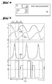
- To Fig. 2 is the motor characteristic of the motor force F (x) and the latching force R (x) for a rotor 3 ( Fig. 1 ) with a periodically alternating in an axial pole pitch P permanent magnet 12 ( Fig. 1 ) and associated poles 13 ( Fig. 1 ) of the stator 14 ( Fig. 1 ).
- the motor force F (x) also changes direction.
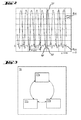
- FIG. 3 has this as an algorithm for the computing means 9 ( Fig. 1 ) associated control method 16 for a striking hand tool 1 ( Fig. 1 ) according to the illustrated status diagram, multiple (by the user directly or indirectly by the boundary conditions) selectable operating states 17a, 17b, 17c, namely the stable impact operation 17a with active linear motor 2 ( Fig. 1 ) and to the workpiece attached or just above the workpiece guided (Schwebeleisseln) tool 7 ( Fig. 1 ), the idle mode 17b with active linear motor 2 ( Fig. 1 ) and tool 7 away from the workpiece (FIG. Fig. 1 ) and the idle mode 17c with deactivated linear motor 2 ( Fig. 1 ). Between all operating states 17a, 17b, 17c can be changed in both directions.
- a lighting step 19 is carried out which consists of previously calculated or stored data of a desired kinematic state S (x (t + [delta] t), v (t + [delta] t), a (t + [delta] t)) of the Runner 3 ( Fig. 1 ) at the time t + [delta] t the current i (t) of the exciting coil (s) 10 ( Fig. 1 ) of the linear motor 2 ( Fig. 1 ) determines which of the power electronics 33 ( Fig. 1 ) controlled by the exciting coil (s) 10 ( Fig. 1 ) and the necessary motor force F (x (t)) ( Fig. 2 ) causes.
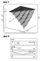
- the computing means 9 ( Fig. 1 ) to a stored in the memory measurement data 20 ( Fig. 8 ) of the percussion characteristic curve and interpolates this.
- the energizing step 19 additionally comprises a pole phase calculation 21, which results from the position x (t) of the rotor 3 (FIG. Fig. 1 ) calculates the pole phase [phi] (x) within the pole pitch P.
- the computing means 9 ( Fig. 1 ) the motor characteristic ( Fig. 2 ) by simple trigonometric functions over the pole phase [phi] (x).
- the necessary current intensity i (t) is determined, whose energization by the excitation coil (s) 10 (FIG. Fig. 1 ) the motor force F (x (t)) ( Fig. 2 ) generated.
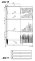
- FIG. 5 To Fig. 5 are in operating state 17a ( Fig. 3 ) of stable impact operation, in which the rotor 3 ( Fig. 1 ) between a piston 5 ( Fig. 1 ) near anterior inflection point W ( Fig. 1 ) and one to the percussion piston 5 ( Fig. 1 ) wide rearward inflection point W ( Fig. 1 ), the rotor position x L (t), the impact piston position x S (t), the air spring pressure p (t) and the engine power F (t) scaled appropriately over time t.
- a feed 34 of the rotor 3 Within each movement period of the period T, a feed 34 of the rotor 3 (FIG. Fig. 1 ) with constant engine power F (t).
- Fig. 6 are in another operating state 17b ( Fig. 3 ) than that of stable impact operation in the form of idling operation, in which due to the far forward offset tool 7 (FIG. Fig.1 ) the percussion piston 5 ( Fig. 1 ) far forward (not shown) and the vent 32 ( Fig. 1 ), the rotor position xL (t), the impact piston position xS (t), the air spring pressure p (t) and the engine power F (t) scaled appropriately over time t.
- a deceleration step 18 is additionally carried out, in which the impact piston 5 (FIG. Fig. 1 ) moving runners 3 ( Fig. 1 ) is delayed electromagnetically.
- Calculating means 9 ( Fig. 1 ) by numerically integrating the sum of the product terms u (t) i (t) and F (t) v (t) over a period T ( Fig. 6 ), ie, for example. 0.02s, is calculated.
- Fig. 8 contains this in the memory of the computing means 9 ( Fig. 1 ) stored measuring data array 20 'of the deceleration process as input variables, the sensed rotor position x (t) and the rotor speed v (t) and as output value, the calculated position xW of the front inflection point W ( Fig. 1 ).
- the clearly recognizable ripple results in the pole pitch P ( Fig. 4 ) of the rotor 3 ( Fig. 1 ).
- Plateau represents the position of the front abutment member 11b (FIG. Fig. 1 ), just before that by delaying the inflection point W ( Fig. 1 ) should be enforced.
- the planting step 23, 23 ' has a braking step 24 with the movement of the rotor 3 (FIG. Fig. 1 ) decelerating motor force F (t), in which the rotor 3 ( Fig. 1 ) gently to the applying element 11a, 11b ( Fig. 1 ) is approximated.
- the attachment step 23, 23 ' also has a chronologically later holding step 25 with the movement of accelerating motor force F (t), in which the rotor 3 (FIG. Fig. 1 ) is temporarily held there.
- the braking step 24 is preceded by a calculation step 22 ', which consists of sensor-recorded data of the kinematic IstschulsWrits (x (t), v (t), a (t)) of the rotor 3 ( Fig.1 ) with the computing means 9 ( Fig.1 ) calculates a braking time tB at which the braking step 24 starts.
- the computing means 9 ( Fig.1 ) to the stored in the memory measurement data array 20 "(analog Fig. 8 ) of the braking process and interpolates this.
- the velocity v (t) and the position x (t) of the actual kinematic state l ((x (t), v (t), a (t))) of the rotor 3 sensed by two axially offset sensors 8 ( Fig. 1 ) in the form of the axial sensor array the passage time of the rotor 3 ( Fig.1 ) to capture.
- the holding step 25 is preceded by a trigger step 26, which consists of sensory data of the kinematic IstschulsWrits (x (t), v (t), a (t)) of the rotor 3 ( Fig.1 ) with the computing means 9 ( Fig.1 ) calculates a trigger condition B for the holding time tH at which the holding step 25 starts.
- a speed v (t) and / or a position x (t) of the kinematic IstschulsWrits (x (t), v (t), a (t)) of the rotor 3 ( Fig.1 ) sensed and compared with a speed limit and / or a position barrier.
- the axial sensor array 8 (FIG. Fig.1 ) with a close to the contact element 11a, 11b ( Fig.1 ) positioned sensor the passage time of the rotor 3 ( Fig.1 ).
- the braking step 24, 24 includes a force control circuit 27 for regulating the smooth gentle approaching speed v (t) to the abutment element 11a, 11b (FIG. Fig. 1 ) required motor force F (t).
- the axial sensor array with a plurality of close to the application element 11a, 11b ( Fig.1 ) positioned sensors 8 ( Fig.1 ) a plurality of passage times of the rotor 3 ( Fig.1 ).
- FIG. 10 To Fig. 10 are at the transition of the idle operation 17c ( Fig. 3 ) for stable impact operation 17a ( Fig. 3 ) the rotor position xL (t), the impact position xS (t), the air spring pressure p (t) and the engine power F (t) are scaled appropriately over the time t, after a disengaging step 37 for disengaging the rotor 3 (FIG. Fig. 1 ) from the latching means 15 ( Fig. 1 ) in a suction step 38 for sucking the impact piston 5, which is currently no longer in the front striking position (FIG. Fig. 1 ) within the first movement period, an investment step 39 of the rotor 3 ( Fig. 1 ) to the front application element 11b (FIG. Fig. 1 ) takes place at which, for a blow-off time tA, the seven period durations T of the stable beat operation 17a (FIG. Fig. 3 ), a holding step 25 connects.
- Fig. 11 takes place via the (user-operated) handset 40 ( Fig. 1 ) controlled transition to idle mode 17c ( Fig. 4 ) an attachment step 23 to the rear application element 11a ( Fig. 1 ), followed by a latching step 41 which connects the rotor 3 (FIG. Fig. 1 ) on the rear abutment element 11a ( Fig. 1 ) engages mechanically.
- a Ausrast Colour 42 executed.
Landscapes
- Engineering & Computer Science (AREA)
- Power Engineering (AREA)
- Mechanical Engineering (AREA)
- Microelectronics & Electronic Packaging (AREA)
- Physics & Mathematics (AREA)
- Electromagnetism (AREA)
- Percussive Tools And Related Accessories (AREA)
Applications Claiming Priority (1)
| Application Number | Priority Date | Filing Date | Title |
|---|---|---|---|
| DE102007000488A DE102007000488A1 (de) | 2007-09-12 | 2007-09-12 | Handwerkzeugmaschine mit Luftfederschlagswerk, Linearmotor und Steuerverfahren |
Publications (2)
| Publication Number | Publication Date |
|---|---|
| EP2036680A2 true EP2036680A2 (fr) | 2009-03-18 |
| EP2036680A3 EP2036680A3 (fr) | 2012-10-31 |
Family
ID=40104729
Family Applications (1)
| Application Number | Title | Priority Date | Filing Date |
|---|---|---|---|
| EP08105156A Withdrawn EP2036680A3 (fr) | 2007-09-12 | 2008-08-27 | Machine-outil manuelle dotée d'un mécanisme de percussion à ressort pneumatique, moteur linéaire et procédé de commande |
Country Status (3)
| Country | Link |
|---|---|
| US (1) | US7926584B2 (fr) |
| EP (1) | EP2036680A3 (fr) |
| DE (1) | DE102007000488A1 (fr) |
Cited By (9)
| Publication number | Priority date | Publication date | Assignee | Title |
|---|---|---|---|---|
| EP2189249A1 (fr) * | 2008-11-25 | 2010-05-26 | Robert Bosch GmbH | Dispositif de machine-outil et machine-outil |
| EP2551059A1 (fr) * | 2011-07-26 | 2013-01-30 | HILTI Aktiengesellschaft | Machine-outil manuelle avec une assise à trois points |
| WO2013174594A1 (fr) * | 2012-05-25 | 2013-11-28 | Robert Bosch Gmbh | Unité de percussion |
| WO2013174600A1 (fr) * | 2012-05-25 | 2013-11-28 | Robert Bosch Gmbh | Unité de percussion |
| EP2674255A1 (fr) * | 2012-06-15 | 2013-12-18 | HILTI Aktiengesellschaft | Procédé de commande pour une machine-outil et machine-outil |
| WO2013186050A1 (fr) * | 2012-06-15 | 2013-12-19 | Hilti Aktiengesellschaft | Procédé de commande pour une machine-outil, et machine-outil |
| EP2676773A1 (fr) * | 2012-06-19 | 2013-12-25 | HILTI Aktiengesellschaft | Appareil de pose et procédé de commande |
| WO2020259870A1 (fr) * | 2019-06-26 | 2020-12-30 | Rhefor Gbr | Appareil de pose à guidage manuel |
| EP4296006A1 (fr) * | 2022-06-21 | 2023-12-27 | Robert Bosch GmbH | Machine-outil et procédé de fonctionnement d'une machine-outil |
Families Citing this family (36)
| Publication number | Priority date | Publication date | Assignee | Title |
|---|---|---|---|---|
| DE102007000085A1 (de) * | 2007-02-13 | 2008-08-14 | Hilti Ag | Verfahren zur Steuerung eines Linearmotors zum Antrieb eines Schlagwerks |
| US8636081B2 (en) | 2011-12-15 | 2014-01-28 | Milwaukee Electric Tool Corporation | Rotary hammer |
| US8695726B2 (en) * | 2010-12-29 | 2014-04-15 | Medical Enterprises LLC | Electric motor driven tool for orthopedic impacting |
| US8393409B2 (en) | 2010-12-29 | 2013-03-12 | Ortho Technologies, Llc | Electric motor driven tool for orthopedic impacting |
| EP3284429B1 (fr) * | 2010-12-29 | 2024-11-06 | DePuy Synthes Products, Inc. | Outil entraîné par moteur électrique pour impact orthopédique |
| US8936106B2 (en) * | 2010-12-29 | 2015-01-20 | Medical Enterprises LLC | Electric motor driven tool for orthopedic impacting |
| EP3162314B1 (fr) * | 2010-12-29 | 2019-02-27 | DePuy Synthes Products, Inc. | Outil entraîné par moteur électrique pour impact orthopédique |
| US8936105B2 (en) * | 2010-12-29 | 2015-01-20 | Medical Enterprises LLC | Electric motor driven tool for orthopedic impacting |
| DE102011077241A1 (de) | 2011-06-09 | 2012-12-13 | Hilti Aktiengesellschaft | Linearmotor, Handwerkzeugmaschine |
| DE102011079819A1 (de) | 2011-07-26 | 2013-01-31 | Hilti Aktiengesellschaft | Handwerkzeugmaschine mit Lagereinrichtung |
| US10149711B2 (en) | 2012-03-30 | 2018-12-11 | Depuy Mitek, Llc | Surgical impact tool |
| WO2013174641A1 (fr) * | 2012-05-25 | 2013-11-28 | Robert Bosch Gmbh | Unité de percussion |
| DE102012208870A1 (de) * | 2012-05-25 | 2013-11-28 | Robert Bosch Gmbh | Schlagwerkeinheit |
| DE102012210082A1 (de) * | 2012-06-15 | 2013-12-19 | Hilti Aktiengesellschaft | Werkzeugmaschine und Steuerungsverfahren |
| DE102012210088A1 (de) * | 2012-06-15 | 2013-12-19 | Hilti Aktiengesellschaft | Werkzeugmaschine |
| DE102012210097A1 (de) * | 2012-06-15 | 2013-12-19 | Hilti Aktiengesellschaft | Steuerungsverfahren |
| US10052747B2 (en) * | 2012-09-03 | 2018-08-21 | Makita Corporation | Hammer tool |
| JP6309022B2 (ja) * | 2012-12-21 | 2018-04-11 | アトラス・コプコ・インダストリアル・テクニーク・アクチボラグ | プッシュスタート機能を有する衝撃レンチ |
| CA2911559C (fr) * | 2013-05-13 | 2018-08-21 | Ear and Skull Base Center, P.C. | Systemes et procedes pour appliquer des stimuli par conduction osseuse et pour mesurer les fonctions des recepteurs gravitationnels de l'oreille interne |
| WO2015000129A1 (fr) * | 2013-07-02 | 2015-01-08 | Chen Zhenyu | Dispositif d'impact et machine-outil pour opération d'impact |
| CN103303242A (zh) * | 2013-07-08 | 2013-09-18 | 无锡商业职业技术学院 | 一种电动逃生锤 |
| EP2857150A1 (fr) * | 2013-10-03 | 2015-04-08 | HILTI Aktiengesellschaft | Machine-outil manuelle |
| CN105757205B (zh) * | 2014-11-12 | 2017-10-27 | 力纳克传动系统(深圳)有限公司 | 线性传动器系统 |
| CN105752876B (zh) * | 2014-11-12 | 2017-12-22 | 力纳克传动系统(深圳)有限公司 | 线性传动器系统 |
| ITUB20160572A1 (it) * | 2016-01-19 | 2017-07-19 | Ciro Tarallo | Martello trapano escavatore a percussione a repulsione elettromagnetica |
| US20180193993A1 (en) * | 2017-01-09 | 2018-07-12 | Tricord Solutions, Inc. | Compact Impacting Apparatus |
| WO2019079560A1 (fr) | 2017-10-20 | 2019-04-25 | Milwaukee Electric Tool Corporation | Outil à percussion |
| US12023299B2 (en) * | 2017-11-27 | 2024-07-02 | Jaguar Precision Industry Co., Ltd. | Massage device |
| US11059155B2 (en) | 2018-01-26 | 2021-07-13 | Milwaukee Electric Tool Corporation | Percussion tool |
| EP3672064A1 (fr) * | 2018-12-18 | 2020-06-24 | Hilti Aktiengesellschaft | Procédé de commande de moteur |
| JP7210291B2 (ja) * | 2019-01-10 | 2023-01-23 | 株式会社マキタ | 電動ドライバドリル |
| CN110259375B (zh) * | 2019-06-14 | 2021-04-20 | 浙江理工大学 | 用于低冲击场合的电磁谐振式气动冲击器及其工作方法 |
| EP3838490A1 (fr) | 2019-12-20 | 2021-06-23 | Hilti Aktiengesellschaft | Appareil de travail |
| EP3838491A1 (fr) * | 2019-12-20 | 2021-06-23 | Hilti Aktiengesellschaft | Appareil de travail |
| GB2616917A (en) * | 2022-03-26 | 2023-09-27 | Webster Tech Limited | Power tool |
| CN118769188A (zh) * | 2023-04-07 | 2024-10-15 | 喜利得股份公司 | 具有磁力冲击机构的电动工具 |
Citations (6)
| Publication number | Priority date | Publication date | Assignee | Title |
|---|---|---|---|---|
| GB1396812A (en) | 1973-04-24 | 1975-06-04 | Vnii Mekhanizirovannogo I Ruch | Electric tools |
| US4553074A (en) | 1982-08-03 | 1985-11-12 | Martelec Societe Civile Particuliere | Method of and apparatus for the autosynchronization of an electromagnetic hammer |
| EP0718075A1 (fr) | 1994-12-19 | 1996-06-26 | Moshe Averbukh | Dispositif électromagnétique à percussion |
| EP1472050A1 (fr) | 2002-02-06 | 2004-11-03 | Wacker Construction Equipment AG | Outil de percussion pneumatique dote d'un piston d'entrainement electrodynamique |
| DE102005017483A1 (de) | 2005-04-15 | 2006-10-19 | Compact Dynamics Gmbh | Linearaktor in einem Elektro-Schlagwerkzeug |
| WO2007000344A1 (fr) | 2005-06-29 | 2007-01-04 | Wacker Construction Equipment Ag | Mecanisme de percussion a entrainement lineaire electrodynamique |
Family Cites Families (10)
| Publication number | Priority date | Publication date | Assignee | Title |
|---|---|---|---|---|
| DE898879C (de) * | 1951-10-30 | 1953-12-03 | Elmeg | Einrichtung an elektromagnetischen Schlaggeraeten |
| US3054464A (en) * | 1958-06-04 | 1962-09-18 | Supreme Products Corp | Electric hammer |
| JPS5099565U (fr) * | 1974-01-16 | 1975-08-18 | ||
| US6137195A (en) * | 1996-03-28 | 2000-10-24 | Anorad Corporation | Rotary-linear actuator |
| JP3292972B2 (ja) * | 1996-03-29 | 2002-06-17 | 株式会社マキタ | 打撃工具 |
| DE19828426C2 (de) * | 1998-06-25 | 2003-04-03 | Wacker Werke Kg | Antriebskolben mit geringer Wandstärke für ein Luftfederschlagwerk |
| BR9907432B1 (pt) * | 1999-12-23 | 2014-04-22 | Brasil Compressores Sa | Método de controle de compressor, sistema de monitoração de posição de um pistão e compressor |
| DE10111717C1 (de) * | 2001-03-12 | 2002-10-24 | Wacker Werke Kg | Luftfederschlagwerk mit bewegungsfrequenzgesteuertem Leerlaufzustand |
| DE10219950C1 (de) * | 2002-05-03 | 2003-10-30 | Hilti Ag | Pneumatisches Schlagwerk mit magnetfeldempfindlichen Sensor |
| DE102005036560A1 (de) * | 2005-08-03 | 2007-02-08 | Wacker Construction Equipment Ag | Bohr- und/oder Schlaghammer mit Linearantrieb und Luftkühlung |
-
2007
- 2007-09-12 DE DE102007000488A patent/DE102007000488A1/de not_active Withdrawn
-
2008
- 2008-08-26 US US12/229,800 patent/US7926584B2/en active Active
- 2008-08-27 EP EP08105156A patent/EP2036680A3/fr not_active Withdrawn
Patent Citations (6)
| Publication number | Priority date | Publication date | Assignee | Title |
|---|---|---|---|---|
| GB1396812A (en) | 1973-04-24 | 1975-06-04 | Vnii Mekhanizirovannogo I Ruch | Electric tools |
| US4553074A (en) | 1982-08-03 | 1985-11-12 | Martelec Societe Civile Particuliere | Method of and apparatus for the autosynchronization of an electromagnetic hammer |
| EP0718075A1 (fr) | 1994-12-19 | 1996-06-26 | Moshe Averbukh | Dispositif électromagnétique à percussion |
| EP1472050A1 (fr) | 2002-02-06 | 2004-11-03 | Wacker Construction Equipment AG | Outil de percussion pneumatique dote d'un piston d'entrainement electrodynamique |
| DE102005017483A1 (de) | 2005-04-15 | 2006-10-19 | Compact Dynamics Gmbh | Linearaktor in einem Elektro-Schlagwerkzeug |
| WO2007000344A1 (fr) | 2005-06-29 | 2007-01-04 | Wacker Construction Equipment Ag | Mecanisme de percussion a entrainement lineaire electrodynamique |
Cited By (17)
| Publication number | Priority date | Publication date | Assignee | Title |
|---|---|---|---|---|
| EP2189249A1 (fr) * | 2008-11-25 | 2010-05-26 | Robert Bosch GmbH | Dispositif de machine-outil et machine-outil |
| US9314912B2 (en) | 2011-07-26 | 2016-04-19 | Hilti Aktiengesellschaft | Hand-held power tool with a three-point mounting |
| EP2551059A1 (fr) * | 2011-07-26 | 2013-01-30 | HILTI Aktiengesellschaft | Machine-outil manuelle avec une assise à trois points |
| US10350742B2 (en) | 2012-05-25 | 2019-07-16 | Robert Bosch Gmbh | Percussion unit |
| WO2013174594A1 (fr) * | 2012-05-25 | 2013-11-28 | Robert Bosch Gmbh | Unité de percussion |
| WO2013174600A1 (fr) * | 2012-05-25 | 2013-11-28 | Robert Bosch Gmbh | Unité de percussion |
| US9969071B2 (en) | 2012-05-25 | 2018-05-15 | Robert Bosch Gmbh | Percussion unit |
| US9987737B2 (en) | 2012-06-15 | 2018-06-05 | Hilti Aktiengesellschaft | Control method for a machine tool and a machine tool |
| WO2013186050A1 (fr) * | 2012-06-15 | 2013-12-19 | Hilti Aktiengesellschaft | Procédé de commande pour une machine-outil, et machine-outil |
| CN103507042A (zh) * | 2012-06-15 | 2014-01-15 | 喜利得股份公司 | 工具机和控制方法 |
| EP2674255A1 (fr) * | 2012-06-15 | 2013-12-18 | HILTI Aktiengesellschaft | Procédé de commande pour une machine-outil et machine-outil |
| TWI624336B (zh) * | 2012-06-19 | 2018-05-21 | 列支敦斯登商希爾悌股份有限公司 | 施加器具與控制方法 |
| EP2676773A1 (fr) * | 2012-06-19 | 2013-12-25 | HILTI Aktiengesellschaft | Appareil de pose et procédé de commande |
| WO2020259870A1 (fr) * | 2019-06-26 | 2020-12-30 | Rhefor Gbr | Appareil de pose à guidage manuel |
| US11883938B2 (en) | 2019-06-26 | 2024-01-30 | Rhefor Gbr | Handheld setting tool |
| AU2020306332B2 (en) * | 2019-06-26 | 2026-02-19 | Rhefor Gbr | Handheld setting tool |
| EP4296006A1 (fr) * | 2022-06-21 | 2023-12-27 | Robert Bosch GmbH | Machine-outil et procédé de fonctionnement d'une machine-outil |
Also Published As
| Publication number | Publication date |
|---|---|
| US20090065226A1 (en) | 2009-03-12 |
| US7926584B2 (en) | 2011-04-19 |
| EP2036680A3 (fr) | 2012-10-31 |
| DE102007000488A1 (de) | 2009-03-19 |
Similar Documents
| Publication | Publication Date | Title |
|---|---|---|
| EP2036680A2 (fr) | Machine-outil manuelle dotée d'un mécanisme de percussion à ressort pneumatique, moteur linéaire et procédé de commande | |
| EP2213420B1 (fr) | Procédé de commande et machine-outil manuelle | |
| EP2855095B1 (fr) | Unité de percussion | |
| EP1277548B1 (fr) | Appareil de scellement de chevilles avec réglage de la profondeur de pose | |
| EP1607186A1 (fr) | Perceuse à percussion / marteau piqueur électro-pneumatique à énergie d'impact modifiable | |
| EP1170095A2 (fr) | Outil à main électrique avec interruption de marche en vide | |
| EP2861381B1 (fr) | Procédé de commande pour une machine-outil et machine-outil | |
| EP2855094A1 (fr) | Unité de percussion | |
| DE102007034293A1 (de) | Hubgeregelter Linearverdichter | |
| EP1375077A2 (fr) | Mécanisme de percussion à ressort pneumatique | |
| EP3554765B1 (fr) | Procédé de commande pour une machine-outil manuelle de frappe | |
| EP2213421B1 (fr) | Mécanisme de percussion pneumatique et procédé de commande | |
| DE10047045B4 (de) | Elektrische Steuervorrichtung für Magnetpumpen | |
| DE102011106932B4 (de) | Verfahren zum Betrieb eines Geräts zum Fördern und Dosieren | |
| EP2674253B1 (fr) | Procédé de commande pour une machine-outil | |
| DE102012101341B4 (de) | Anschlagvorrichtung mit Linearmotor | |
| CN110594477A (zh) | 一种用于压电型高速开关阀的软着陆pwm控制方法及系统 | |
| EP2674255B1 (fr) | Procédé de commande pour une machine-outil et machine-outil | |
| EP1352718A1 (fr) | Système pneumatique à percussion | |
| DE10127996A1 (de) | Pumpvorrichtung und Regelvorrichtung | |
| DE20218487U1 (de) | Pneumatisch endlagengedämpfte Antriebsordnung, insbesondere für einen Türantrieb | |
| DE102015218203A1 (de) | Verfahren zur Steuerung eines elektrischen Antriebs sowie elektrischer Antrieb | |
| DE10325706A1 (de) | Verfahren zur Steuerung der Bewegung eines Ankers eines elektromagnetischen Aktuators | |
| DE102011088972A1 (de) | Pneumatische Werkzeugvorrichtung | |
| DE202011100584U1 (de) | Vorrichtung zum Bewegen eines bewegbaren Möbelteils und Möbel |
Legal Events
| Date | Code | Title | Description |
|---|---|---|---|
| PUAI | Public reference made under article 153(3) epc to a published international application that has entered the european phase |
Free format text: ORIGINAL CODE: 0009012 |
|
| AK | Designated contracting states |
Kind code of ref document: A2 Designated state(s): AT BE BG CH CY CZ DE DK EE ES FI FR GB GR HR HU IE IS IT LI LT LU LV MC MT NL NO PL PT RO SE SI SK TR |
|
| AX | Request for extension of the european patent |
Extension state: AL BA MK RS |
|
| PUAL | Search report despatched |
Free format text: ORIGINAL CODE: 0009013 |
|
| AK | Designated contracting states |
Kind code of ref document: A3 Designated state(s): AT BE BG CH CY CZ DE DK EE ES FI FR GB GR HR HU IE IS IT LI LT LU LV MC MT NL NO PL PT RO SE SI SK TR |
|
| AX | Request for extension of the european patent |
Extension state: AL BA MK RS |
|
| RIC1 | Information provided on ipc code assigned before grant |
Ipc: H02K 33/16 20060101ALI20120925BHEP Ipc: B25D 11/06 20060101AFI20120925BHEP Ipc: H02P 25/06 20060101ALI20120925BHEP |
|
| AKY | No designation fees paid | ||
| REG | Reference to a national code |
Ref country code: DE Ref legal event code: R108 |
|
| REG | Reference to a national code |
Ref country code: DE Ref legal event code: R108 Effective date: 20130703 |
|
| STAA | Information on the status of an ep patent application or granted ep patent |
Free format text: STATUS: THE APPLICATION IS DEEMED TO BE WITHDRAWN |
|
| 18D | Application deemed to be withdrawn |
Effective date: 20130503 |