EP2551059A1 - Machine-outil manuelle avec une assise à trois points - Google Patents
Machine-outil manuelle avec une assise à trois points Download PDFInfo
- Publication number
- EP2551059A1 EP2551059A1 EP12172863A EP12172863A EP2551059A1 EP 2551059 A1 EP2551059 A1 EP 2551059A1 EP 12172863 A EP12172863 A EP 12172863A EP 12172863 A EP12172863 A EP 12172863A EP 2551059 A1 EP2551059 A1 EP 2551059A1
- Authority
- EP
- European Patent Office
- Prior art keywords
- bearing
- rotor
- hand tool
- piston
- spherical body
- Prior art date
- Legal status (The legal status is an assumption and is not a legal conclusion. Google has not performed a legal analysis and makes no representation as to the accuracy of the status listed.)
- Granted
Links
Images
Classifications
-
- B—PERFORMING OPERATIONS; TRANSPORTING
- B25—HAND TOOLS; PORTABLE POWER-DRIVEN TOOLS; MANIPULATORS
- B25D—PERCUSSIVE TOOLS
- B25D11/00—Portable percussive tools with electromotor or other motor drive
- B25D11/06—Means for driving the impulse member
-
- B—PERFORMING OPERATIONS; TRANSPORTING
- B25—HAND TOOLS; PORTABLE POWER-DRIVEN TOOLS; MANIPULATORS
- B25D—PERCUSSIVE TOOLS
- B25D11/00—Portable percussive tools with electromotor or other motor drive
- B25D11/06—Means for driving the impulse member
- B25D11/064—Means for driving the impulse member using an electromagnetic drive
-
- B—PERFORMING OPERATIONS; TRANSPORTING
- B25—HAND TOOLS; PORTABLE POWER-DRIVEN TOOLS; MANIPULATORS
- B25D—PERCUSSIVE TOOLS
- B25D17/00—Details of, or accessories for, portable power-driven percussive tools
- B25D17/28—Supports; Devices for holding power-driven percussive tools in working position
-
- H—ELECTRICITY
- H02—GENERATION; CONVERSION OR DISTRIBUTION OF ELECTRIC POWER
- H02K—DYNAMO-ELECTRIC MACHINES
- H02K33/00—Motors with reciprocating, oscillating or vibrating magnet, armature or coil system
- H02K33/16—Motors with reciprocating, oscillating or vibrating magnet, armature or coil system with polarised armatures moving in alternate directions by reversal or energisation of a single coil system
-
- H—ELECTRICITY
- H02—GENERATION; CONVERSION OR DISTRIBUTION OF ELECTRIC POWER
- H02K—DYNAMO-ELECTRIC MACHINES
- H02K41/00—Propulsion systems in which a rigid body is moved along a path due to dynamo-electric interaction between the body and a magnetic field travelling along the path
- H02K41/02—Linear motors; Sectional motors
- H02K41/03—Synchronous motors; Motors moving step by step; Reluctance motors
- H02K41/031—Synchronous motors; Motors moving step by step; Reluctance motors of the permanent magnet type
-
- B—PERFORMING OPERATIONS; TRANSPORTING
- B25—HAND TOOLS; PORTABLE POWER-DRIVEN TOOLS; MANIPULATORS
- B25D—PERCUSSIVE TOOLS
- B25D2250/00—General details of portable percussive tools; Components used in portable percussive tools
- B25D2250/245—Spatial arrangement of components of the tool relative to each other
-
- H—ELECTRICITY
- H02—GENERATION; CONVERSION OR DISTRIBUTION OF ELECTRIC POWER
- H02K—DYNAMO-ELECTRIC MACHINES
- H02K7/00—Arrangements for handling mechanical energy structurally associated with dynamo-electric machines, e.g. structural association with mechanical driving motors or auxiliary dynamo-electric machines
- H02K7/08—Structural association with bearings
Definitions
- the invention relates to a hand tool, in particular a chiseling hand tool.
- the linear motor has a stator and a rotor.
- the rotor is mechanically rigidly connected to the excitation piston.
- the rotor of the linear motor is fork-shaped and has two bars, each of which is mounted directly in two in two along a movement axis of the rotor successively arranged air gaps of the stator.
- the two air gaps in the core of the stator each consist of two mutually parallel partial air gaps, which are both configured flat.
- the exciter piston is guided along an axis in a hollow cylinder of the striking mechanism.
- the prior art hand tool has a bearing device having a rotor bearing in the form of the four-dimensional part air gaps for longitudinally movable bearings of the rotor and a exciter piston bearing in the form of a hollow cylinder for supporting the excitation piston.
- the rotor and the stator must be made very precisely matched to each other, in particular the fitting of the mechanism, in particular the air gaps, is relatively expensive. In the case of fitting errors or due to an application-related incorrect change of the fit, there is an increased risk that a runner in the air gaps will be guided in an unclean or with increased resistance or even tilted.
- the invention begins, whose task is to provide a hand tool with a simpler designed yet reliable storage facility for storing the runner.
- the bearing device should be improved over the prior art and be easier to manufacture in production.
- the rotor bearing has a first bearing and a second bearing, which support the rotor on opposite sides, wherein the rotor bearing allows pivoting of the rotor together with the exciter piston about the at least one axis transverse to the axis of movement, and the excitation piston bearing has a third bearing with a longitudinal guide along a movement axis for the exciter piston.
- the invention is based on the consideration that in the previously known hand tool machine, the bearing of the rotor of the linear motor is already overdetermined several times, namely by the four planar partial air gaps, which requires a complicated fitting of these bearings as a result. If an elaborate fitting should be avoided, on the one hand there would be the possibility to make the manufacturing tolerances very low, but this would lead to a comparatively expensive hand tool. Another possibility would be to accept erroneous positions of the runner in the storage facility. However, this results in a friction caused by considerable heat generation, which would ultimately negatively affect the life. The invention assumes that both approaches are disadvantageous.
- the invention has recognized that a rotor bearing with a first bearing and a second bearing, which support the rotor on opposite sides, as well as an exciter piston bearing is basically advantageous.
- a third bearing of the excitation piston bearing thereby provides a longitudinal guide along a movement axis for the exciter piston.
- the assembly of excitation piston and rotor is viewed as a whole and a bearing device is provided, which provides a statically determined, but not overdetermined storage for the assembly of exciter piston and rotor.
- the rotor bearing and the exciter piston bearing with a first, second and third bearing ideally form a three-point bearing.
- the rotor bearing allows pivoting of the rotor together with the excitation piston about the at least one axis lying transversely to the axis of movement. This also provides a degree of freedom in the movement of the runner, which may be advantageous in work operation as well as in an assembly of the rotor in the rotor bearing.
- the first bearing part comprises the rotor laterally and on a top and bottom of the rotor.
- the runner is stored very safe.
- the rotor is supported with play to allow a sufficiently low-resistance longitudinal movement of the rotor in the first and second bearings.
- a particularly advantageous development of the invention is based on the assumption that a rotor of the prior art held and guided directly in the stator can still be improved with regard to its mounting.
- the invention is based on the consideration that it is advantageous to consider a longitudinally movable guide of the rotor on the one hand and a holder of the rotor on the motor or housing separately.
- the rotor bearing first bearing part of the rotor By means of the first bearing part of the rotor is guided in an advantageous manner adapted.
- the rotor bearing first bearing part along at least one axis transverse to the axis of movement is advantageously kept limited movable.
- the bearing device is positioned in the hand tool for storing the rotor in a movement axis of a tool of the power tool.
- the rotor bearing and the excitation piston bearing preferably form a three-point bearing.
- a three-point bearing for supporting an assembly comprising a rotor and a mechanically rigidly coupled excitation piston is provided.
- a rotor bearing and a exciter piston bearing are provided according to the concept of the invention for supporting the rotor, which preferably form a three-point bearing.
- the three-point bearing forms the only storage for the rotor and the excitation piston.
- the rotor bearing has a comparatively small bearing surface or bearing line proportion compared to the total surface of the assembly.
- the exciter piston bearing has a comparatively very small bearing surface or bearing line component in comparison to the overall surface of the assembly. Accordingly, the rotor bearing and excitation piston bearing for the assembly can be described at least approximately as a three-point bearing.
- the invention has recognized that the disadvantages mentioned arise due to an overdetermined storage for a runner and strengthen themselves by a mechanically coupled to the rotor exciter piston. This is due to the fact that the exciter piston also assumes leadership functions and can thus initiate so-called constraining forces in bearings for the linear motor. So far, such constraining forces could only by very small manufacturing tolerances, ie by a very accurate Fitting the bearings, or by elastic intermediate elements, such as a so-called pendulum support to be avoided. However, this leads to a relatively expensive manufacturing process for the power tool.
- the bearing device of the power tool uses the excitation piston as a guide.
- the assembly of exciter piston and rotor is then mounted in three points, preferably two bearing points are provided for the rotor and a bearing point is realized by the excitation piston mounted in a hollow cylinder itself.
- the storage device is statically determined in a particularly preferred manner, but not overdetermined. Therefore arise during operation of the linear motor of the power tool no unnecessary constraining forces and / or constraints and it is also no elaborate fitting necessary.
- the friction forces are comparatively low, so that during operation of the power tool relatively little heat due to frictional forces developed, which has a positive effect on the efficiency and on the life of the power tool in the result.
- the bearing device with the rotor bearing and the excitation piston bearing forms the three-point bearing as the only storage, in particular by two opposing bearing points for the rotor and a bearing point for the excitation piston.
- the excitation piston can be circumferentially flush fitted in a hollow cylinder of a pneumatic hammer mechanism and be guided in the hollow cylinder along a working axis guided by the hollow cylinder.
- the exciter piston drives via an air spring on a likewise arranged in the hollow cylinder percussion piston.
- the exciter piston and the hollow cylinder form another bearing point.
- the two bearing points for the runner can be, for example, flat recesses into which the runner engages.
- the first and second bearings are formed separately from a stator of the linear motor.
- the second bearing part is preferably on the linear motor, for. B. attached to the stator and / or held on the housing.
- the rotor bearing for supporting the rotor on a fixed with a spherical spherical body.
- the spherical body is attached in the hand tool via at least one cap. Due to the spherical shape between the spherical body and the Dome transferred virtually no moments, but at best forces.
- the rotor bearing is statically determined in a particularly improved manner, but not overdetermined.
- the dome is mounted for mounting the spherical body within the housing of the power tool.
- the spherical body has a groove into which the rotor can engage.
- This groove is preferably formed by a flat recess in the spherical body, which is preferably approximately parallel to a cross-sectional area, preferably practically around an equatorial surface of the spherical body.
- the groove itself has a comparatively small bearing surface or bearing line proportion compared to the total area of the assembly.
- the calotte of the rotor bearing has a recess for embracing such a bulge of the spherical body.
- a recess can be realized by a through hole or by a blind hole. Said recess has the advantage that the above-mentioned bulge on the spherical body does not have to be removed consuming, but finally, if necessary, can be left with little laborious processing in the manufacturing process on the spherical body; especially when mounting the dome in the recess is easily absorbed later.
- the recess in the dome is preferably designed such that it may comprise a larger volume than that of the bulge.
- the rotor bearing for biasing the calotte against the spherical body has a spring arrangement, in particular a plate spring.
- the spring arrangement may be provided on one side. Thus, it requires only a few parts for the spring assembly, which reduces the wear of the parts and the complexity of the rotor bearing.
- a further calotte can be provided. This allows a particularly secure attachment of the rotor bearing. There may be provided two springs which clamp both calottes against the spherical body.
- the rotor In the context of another preferred constructive development of the rotor of the linear motor of the power tool is spatförmig.
- the rotor preferably has a rectangular cross section and a rectangular longitudinal section, as well as an overall flat structure. This spatula-shaped rotor preferably engages even in the groove of the spherical body.
- the mechanical coupling between the rotor and the excitation piston is preferably rigid, for example, formed by a rigid rod.
- the excitation piston bearing has, in a preferred further development variant, a hollow cylinder whose cavity is designed to support the exciter piston. In this case, moments between the excitation piston and the rod are not supported, since such excitation piston bearing acts much like a ball joint.
- the excitation piston is designed comparatively short in the axial direction and preferably has a barrel-shaped outer contour.
- a dimension of the excitation piston along a working axis of the pneumatic impact mechanism is, for example, less than 50% of the diameter of the exciter piston.
- a dimension of the exciter piston along a working axis is substantially shorter than the rigid connection between exciter piston and rotor.
- a cylinder jacket surface may be provided with a sealing ring arranged in this.
- the sealing ring for example in the form of an O-ring, be formed.
- the sealing ring may protrude from the lateral surface and is in contact with the inner surface of the hollow cylinder.
- the rotor bearing has a first spherical body, which is fastened via first, in particular two, calotte in the power tool, and a second spherical body which is attached via second, in particular two, calotte in the power tool on.
- first spherical body which is fastened via first, in particular two, calotte in the power tool
- second spherical body which is attached via second, in particular two, calotte in the power tool on.
- the first spherical body has a first groove and the second spherical body has a second groove, wherein the rotor-preferably spatförmig- engages in the first groove and in the second groove.
- the first groove and the second groove preferably lie in a plane that includes a rotor movement axis.
- the bearing device is positioned in the hand tool machine for a bearing of the rotor in a movement axis of a tool, which is driven by a mechanical transmission of the exciter piston. This leads to a particularly compact design of the power tool with a high efficiency.
- the hand tool has, for example, an electropneumatic hammer mechanism, which is driven by the rotor.
- the hand tool is a hammer drill or a chiseling hand tool.
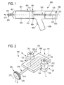
- Fig. 1 schematically shows by way of example a chiseling hand tool 800.
- the hand tool 800 has a housing 801 with a tool holder 802 into which a shank end 803 of a tool 200, for. B. with one of the bit 804, can be used.
- a primary drive of the hand tool 800 is a linear motor 700 which drives a pneumatic percussion 806.
- a user may guide the hand tool 800 by means of a handle 808 and operate it by means of a system switch 809.
- the hand tool 800 drives the bit 804 continuously along a movement axis 210 in the direction of impact 213 in a substrate.
- the percussion 806 has an exciter - here in the form of an excitation piston 400-- and a racket - here in the form of a percussion piston 300--, which are movably guided in a guide tube 510 of an exciter piston bearing 180 of the striking mechanism 806 along the movement axis 210.
- the excitation piston 400 is coupled via a mechanical coupling 500 in the form of a rod to the linear motor 700 and forced to a periodic, linear movement.
- An air spring - formed by a pneumatic chamber 301 - between the exciter and the club couples a movement of the racket to the movement of the exciter.
- the percussion piston 300 can strike directly onto a rear end of the tool 200 or indirectly transfer part of its momentum, in this case to the bit 804, via a substantially stationary intermediate striker.
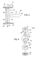
- Fig. 2 shows a schematic representation of an embodiment of a bearing device 100 with a rotor bearing 120th
- Fig. 4 shows a first and second bearings 10, 20 of the rotor bearing 120 in detail in an exploded view and to which reference is made.
- the bearing device 100 For supporting a rotor 600 of a linear motor 700, the bearing device 100 according to the concept of the invention in a hand tool 800 - for example in the manner of a Fig. 1 schematically illustrated embodiment integrated.
- the rotor 600, the guide tube 510 and the excitation piston 400 are mounted in a movement axis 210, along which a tool 200 of the power tool 800 can move.
- the storage device 100 forms with its two-part - a first and second bearing 10, 20 having - rotor bearing 120 and - its - a third bearing 30 having - exciter piston 180 a certain, but not overdetermined three-point bearing.
- the bearing device 100 thus supports the assembly of exciter piston 400 and rotor 600 connected via a mechanical coupling 500; in other words, the assembly of exciter piston 400 and rotor 600 is mounted as a whole; not about the exciter piston 400 and rotor 600 separately stored.
- the three idealized bearing points of the three-point bearing formed by the first second and third bearings 10, 20, 30 are explained in more detail below. In particular, the details of the 3 and FIG. 4 Referenced.
- the excitation piston 400 has a barrel-shaped outer contour and is mounted in a exciter piston bearing 180 with a guide tube 510 in the form of a hollow cylinder 182.
- the excitation piston 400 can slide along the cavity 184 of the hollow cylinder 182 along.
- the exciter piston has a cylinder jacket surface 410 with a sealing ring 420 arranged in the latter, for example an O-ring.
- the excitation piston 400 has a cylinder jacket surface 410, which - averaged over the sealing ring 420 - is airtight on an inner side of the hollow cylinder 182 can be guided.
- the exciter piston 400 is mechanically coupled to the spatulated rotor 600 via a rod of the mechanical coupling 500 in the guide tube 510.
- the spatulate Rotor 600 is guided in two first bearing parts, which are presently formed as two spherical bodies 122, 124.
- the rotor 600 is for this purpose in two grooves 142, 144 of the two spherical bodies 122, 124.
- the spherical bodies 122, 124 form insofar in the region of their grooves 142, 144 two of the three bearing points of the bearing device 100th
- each groove 142, 144 in the spherical body 122, 124 dimensioned such that a surface pressure between the rotor 600 and the spherical body 122, 124 does not exceed a predetermined maximum.
- the bearing device 100 of the handheld power tool 800 can be dimensioned with regard to a predetermined operating time. Accordingly, depending on forces between rotor 600 and rotor bearing, the sizes of the surfaces in the groove 142, 144 may be very different. Through the surfaces of the groove 142, 144 in the spherical body 122, 124, the minimum diameter of the spherical body 122, 124 is determined in the present case. The dimensions of a later explained dome 132, 134 are tuned to it.
- bulges 126 may be formed, for example in the form of chip points during a machining operation or in the form of a sprue pin or a discharge projection in an injection molding production method. Therefore, the two first dome 132 have a recess 136 which comprise these bulges 126.
- Each of the two first bearing parts is thus limited movably held in two second bearing parts; and in the present case limitedly movable along at least one first axis 211 lying transverse to the movement axis 210 and also along at least one second other axis 212 transverse to the movement axis 210.
- the movement axis 210 and the transverse axes 211, 212 form a Cartesian here coordinate system.
- the two second bearing parts are fastened in the stator 650 of the linear motor 700 via two calottes 132, 134 in each case.
- the rotor 600 is longitudinally movably guided at a center position of the spherical body 122 with the first groove 142 and a center position of the spherical body 124 with the second groove 144.
- the idealized points of the three-point bearing correspond to the bearing points 1, 2, 3.
- the third bearing point 3 marks thereby approximately a center of gravity of the Excitation piston 400 - here a crossing point of the movement axis 210 with a diameter D of the exciter piston 400 transverse to the axis of movement 210th
- disc springs 150 is provided.
- the cup springs 150 clamp on one side - in an embodiment not shown here on both sides - the first domes 132 against the first spherical body 122.
- the first and second bearings 10, 20 are here similar, mirrored here, formed so that Fig. 4 applies to both.
Landscapes
- Engineering & Computer Science (AREA)
- Mechanical Engineering (AREA)
- Physics & Mathematics (AREA)
- Electromagnetism (AREA)
- Power Engineering (AREA)
- Chemical & Material Sciences (AREA)
- Combustion & Propulsion (AREA)
- Connection Of Motors, Electrical Generators, Mechanical Devices, And The Like (AREA)
- Manufacture Of Motors, Generators (AREA)
- Sliding-Contact Bearings (AREA)
Applications Claiming Priority (1)
| Application Number | Priority Date | Filing Date | Title |
|---|---|---|---|
| DE102011079828A DE102011079828A1 (de) | 2011-07-26 | 2011-07-26 | Handwerkzeugmaschine mit Dreipunktlagerung |
Publications (2)
| Publication Number | Publication Date |
|---|---|
| EP2551059A1 true EP2551059A1 (fr) | 2013-01-30 |
| EP2551059B1 EP2551059B1 (fr) | 2017-01-04 |
Family
ID=46319035
Family Applications (1)
| Application Number | Title | Priority Date | Filing Date |
|---|---|---|---|
| EP12172863.8A Active EP2551059B1 (fr) | 2011-07-26 | 2012-06-21 | Machine-outil manuelle avec une assise à trois points |
Country Status (3)
| Country | Link |
|---|---|
| US (1) | US9314912B2 (fr) |
| EP (1) | EP2551059B1 (fr) |
| DE (1) | DE102011079828A1 (fr) |
Families Citing this family (4)
| Publication number | Priority date | Publication date | Assignee | Title |
|---|---|---|---|---|
| US10207347B2 (en) * | 2012-12-27 | 2019-02-19 | Robert Bosch Tool Corporation | Reciprocating tool with inverse bushing |
| ITUB20160572A1 (it) * | 2016-01-19 | 2017-07-19 | Ciro Tarallo | Martello trapano escavatore a percussione a repulsione elettromagnetica |
| EP3697574B1 (fr) | 2017-10-20 | 2025-03-19 | Milwaukee Electric Tool Corporation | Outil à percussion |
| EP3743245B1 (fr) | 2018-01-26 | 2024-04-10 | Milwaukee Electric Tool Corporation | Outil à percussion |
Citations (5)
| Publication number | Priority date | Publication date | Assignee | Title |
|---|---|---|---|---|
| CH172143A (de) * | 1934-05-25 | 1934-09-30 | Lustenberger Alfred | Elektrisches Schlagwerkzeug. |
| DE1106707B (de) * | 1959-08-01 | 1961-05-10 | Heinrich Brune | Gleichstrommagnethammer |
| DE1109109B (de) * | 1957-05-22 | 1961-06-15 | Pietro Aurelio Macchioni | Wechselstrommagnethammer |
| DE10332521A1 (de) * | 2003-07-17 | 2005-02-03 | Robert Bosch Gmbh | Handwerkzeugmaschine mit hin- und herbewegtem Werkzeug und Bewegungsregelung |
| EP2036680A2 (fr) * | 2007-09-12 | 2009-03-18 | HILTI Aktiengesellschaft | Machine-outil manuelle dotée d'un mécanisme de percussion à ressort pneumatique, moteur linéaire et procédé de commande |
Family Cites Families (15)
| Publication number | Priority date | Publication date | Assignee | Title |
|---|---|---|---|---|
| DE1756300U (de) * | 1956-04-12 | 1957-11-14 | Elmeg | Elektromagnetisches schlaggeraet. |
| DE1438257A1 (de) * | 1962-01-13 | 1968-10-24 | Associated Elek Cal Ind Ltd | Sich selbsttaetig einstellende Lagerung |
| DE3529483C1 (de) * | 1985-08-16 | 1989-06-29 | Siemens AG, 1000 Berlin und 8000 München | Verfahren zur Einstellung des Axialspiels zwischen Rotor und Stator eines Elektromotors |
| JP2561361B2 (ja) * | 1990-04-16 | 1996-12-04 | キヤノン株式会社 | 直線駆動装置 |
| US5666715A (en) * | 1995-07-05 | 1997-09-16 | Harris Corporation | Electrically operated impact tool gun |
| DE19700392A1 (de) * | 1996-01-10 | 1997-07-17 | Schieber Universal Maschf | Antriebsvorrichtung mit mehreren flachen Linearmotoren |
| US6137195A (en) * | 1996-03-28 | 2000-10-24 | Anorad Corporation | Rotary-linear actuator |
| DE10025371A1 (de) * | 2000-05-23 | 2001-11-29 | Hilti Ag | Handwerkzeuggerät mit elektromagnetischem Schlagwerk |
| US6611074B2 (en) * | 2001-04-12 | 2003-08-26 | Ballado Investments Inc. | Array of electromagnetic motors for moving a tool-carrying sleeve |
| DE10156388A1 (de) * | 2001-11-16 | 2003-06-05 | Bosch Gmbh Robert | Handwerkzeugmaschine mit einem pneumatischen Schlagwerk |
| CN100574059C (zh) * | 2002-01-16 | 2009-12-23 | 科龙勇发株式会社 | 线性电动机 |
| DE10204861B4 (de) * | 2002-02-06 | 2004-01-29 | Wacker Construction Equipment Ag | Luftfederschlagwerk mit elektrodynamisch bewegtem Antriebskolben |
| US6763789B1 (en) * | 2003-04-01 | 2004-07-20 | Ford Global Technologies, Llc | Electromagnetic actuator with permanent magnet |
| DE102005017483B4 (de) * | 2005-04-15 | 2007-04-05 | Compact Dynamics Gmbh | Linearaktor in einem Elektro-Schlagwerkzeug |
| US7812500B1 (en) * | 2008-11-12 | 2010-10-12 | Demetrius Calvin Ham | Generator / electric motor |
-
2011
- 2011-07-26 DE DE102011079828A patent/DE102011079828A1/de not_active Withdrawn
-
2012
- 2012-06-21 EP EP12172863.8A patent/EP2551059B1/fr active Active
- 2012-07-25 US US13/558,066 patent/US9314912B2/en active Active
Patent Citations (6)
| Publication number | Priority date | Publication date | Assignee | Title |
|---|---|---|---|---|
| CH172143A (de) * | 1934-05-25 | 1934-09-30 | Lustenberger Alfred | Elektrisches Schlagwerkzeug. |
| DE1109109B (de) * | 1957-05-22 | 1961-06-15 | Pietro Aurelio Macchioni | Wechselstrommagnethammer |
| DE1106707B (de) * | 1959-08-01 | 1961-05-10 | Heinrich Brune | Gleichstrommagnethammer |
| DE10332521A1 (de) * | 2003-07-17 | 2005-02-03 | Robert Bosch Gmbh | Handwerkzeugmaschine mit hin- und herbewegtem Werkzeug und Bewegungsregelung |
| EP2036680A2 (fr) * | 2007-09-12 | 2009-03-18 | HILTI Aktiengesellschaft | Machine-outil manuelle dotée d'un mécanisme de percussion à ressort pneumatique, moteur linéaire et procédé de commande |
| DE102007000488A1 (de) | 2007-09-12 | 2009-03-19 | Hilti Aktiengesellschaft | Handwerkzeugmaschine mit Luftfederschlagswerk, Linearmotor und Steuerverfahren |
Also Published As
| Publication number | Publication date |
|---|---|
| DE102011079828A1 (de) | 2013-01-31 |
| US20130186664A1 (en) | 2013-07-25 |
| EP2551059B1 (fr) | 2017-01-04 |
| US9314912B2 (en) | 2016-04-19 |
Similar Documents
| Publication | Publication Date | Title |
|---|---|---|
| DE3328886C2 (de) | Elektrischer Bohrhammer | |
| DE19505068A1 (de) | Geräuschreduzierungsmechanismus für Schlagwerkzeuge | |
| EP2551059B1 (fr) | Machine-outil manuelle avec une assise à trois points | |
| DE2409206A1 (de) | Schlagbohrer | |
| DE19726383A1 (de) | Elektrowerkzeugmaschine | |
| WO2002020224A1 (fr) | Porte-outil pour une machine-outil | |
| CH693023A5 (de) | Bohrhammer. | |
| EP3623085B1 (fr) | Mandrin | |
| DE202018100761U1 (de) | Verbesserte Transfermaschine | |
| EP1716979A1 (fr) | Marteau perforateur ou marteau-burineur | |
| DE102012103111B4 (de) | Werkzeug zum Aufbringen kleiner Schlagimpulse | |
| DE10312980A1 (de) | Elektrohandwerkzeugmaschine | |
| DE2207961C2 (de) | Einrichtung an einem tragbaren, motorisch angetrieben Gesteinsaufbruchhammer zur axial beweglichen Führung eines Werkzeugs | |
| DE2408362A1 (de) | Schlagbohrer | |
| EP2655018A1 (fr) | Machine-outil à main | |
| WO2020020531A1 (fr) | Machine-outil portative, en particulier clé à choc | |
| EP0419866A2 (fr) | Marteau de forage | |
| DE102022103773A1 (de) | Kraftwerkzeug mit einem hammermechanismus | |
| DE1159867B (de) | Schlagschrauber mit drehmomentabhaengiger Abschaltung des insbesondere elektromotorischen Antriebs | |
| DE102020201243B3 (de) | Schnellwechselfutter zur reversiblen Arretierung eines Einsteckwerkzeugs an einem Bearbeitungsgerät | |
| DE2806611A1 (de) | Vorrichtung zum umschalten eines elektropneumatischen bohrhammers von drehbohren auf schlagbohren | |
| WO1999056919A1 (fr) | Machine-outil a changement d'outil | |
| WO2008080653A1 (fr) | Mécanisme de percussion d'une machine-outil électrique portative | |
| CH710973B1 (de) | Spindel mit einem auslenkbaren Werkzeugkopf. | |
| DE810498C (de) | Elektrohammer |
Legal Events
| Date | Code | Title | Description |
|---|---|---|---|
| PUAI | Public reference made under article 153(3) epc to a published international application that has entered the european phase |
Free format text: ORIGINAL CODE: 0009012 |
|
| AK | Designated contracting states |
Kind code of ref document: A1 Designated state(s): AL AT BE BG CH CY CZ DE DK EE ES FI FR GB GR HR HU IE IS IT LI LT LU LV MC MK MT NL NO PL PT RO RS SE SI SK SM TR |
|
| AX | Request for extension of the european patent |
Extension state: BA ME |
|
| 17P | Request for examination filed |
Effective date: 20130730 |
|
| RBV | Designated contracting states (corrected) |
Designated state(s): AL AT BE BG CH CY CZ DE DK EE ES FI FR GB GR HR HU IE IS IT LI LT LU LV MC MK MT NL NO PL PT RO RS SE SI SK SM TR |
|
| GRAJ | Information related to disapproval of communication of intention to grant by the applicant or resumption of examination proceedings by the epo deleted |
Free format text: ORIGINAL CODE: EPIDOSDIGR1 |
|
| GRAP | Despatch of communication of intention to grant a patent |
Free format text: ORIGINAL CODE: EPIDOSNIGR1 |
|
| INTG | Intention to grant announced |
Effective date: 20160930 |
|
| STAA | Information on the status of an ep patent application or granted ep patent |
Free format text: STATUS: GRANT OF PATENT IS INTENDED |
|
| GRAS | Grant fee paid |
Free format text: ORIGINAL CODE: EPIDOSNIGR3 |
|
| GRAA | (expected) grant |
Free format text: ORIGINAL CODE: 0009210 |
|
| STAA | Information on the status of an ep patent application or granted ep patent |
Free format text: STATUS: THE PATENT HAS BEEN GRANTED |
|
| AK | Designated contracting states |
Kind code of ref document: B1 Designated state(s): AL AT BE BG CH CY CZ DE DK EE ES FI FR GB GR HR HU IE IS IT LI LT LU LV MC MK MT NL NO PL PT RO RS SE SI SK SM TR |
|
| REG | Reference to a national code |
Ref country code: GB Ref legal event code: FG4D Free format text: NOT ENGLISH |
|
| REG | Reference to a national code |
Ref country code: CH Ref legal event code: EP |
|
| REG | Reference to a national code |
Ref country code: AT Ref legal event code: REF Ref document number: 858783 Country of ref document: AT Kind code of ref document: T Effective date: 20170115 |
|
| REG | Reference to a national code |
Ref country code: IE Ref legal event code: FG4D Free format text: LANGUAGE OF EP DOCUMENT: GERMAN |
|
| REG | Reference to a national code |
Ref country code: DE Ref legal event code: R096 Ref document number: 502012009191 Country of ref document: DE |
|
| REG | Reference to a national code |
Ref country code: LT Ref legal event code: MG4D Ref country code: NL Ref legal event code: MP Effective date: 20170104 |
|
| REG | Reference to a national code |
Ref country code: FR Ref legal event code: PLFP Year of fee payment: 6 |
|
| PG25 | Lapsed in a contracting state [announced via postgrant information from national office to epo] |
Ref country code: NL Free format text: LAPSE BECAUSE OF FAILURE TO SUBMIT A TRANSLATION OF THE DESCRIPTION OR TO PAY THE FEE WITHIN THE PRESCRIBED TIME-LIMIT Effective date: 20170104 |
|
| PG25 | Lapsed in a contracting state [announced via postgrant information from national office to epo] |
Ref country code: NO Free format text: LAPSE BECAUSE OF FAILURE TO SUBMIT A TRANSLATION OF THE DESCRIPTION OR TO PAY THE FEE WITHIN THE PRESCRIBED TIME-LIMIT Effective date: 20170404 Ref country code: HR Free format text: LAPSE BECAUSE OF FAILURE TO SUBMIT A TRANSLATION OF THE DESCRIPTION OR TO PAY THE FEE WITHIN THE PRESCRIBED TIME-LIMIT Effective date: 20170104 Ref country code: GR Free format text: LAPSE BECAUSE OF FAILURE TO SUBMIT A TRANSLATION OF THE DESCRIPTION OR TO PAY THE FEE WITHIN THE PRESCRIBED TIME-LIMIT Effective date: 20170405 Ref country code: IS Free format text: LAPSE BECAUSE OF FAILURE TO SUBMIT A TRANSLATION OF THE DESCRIPTION OR TO PAY THE FEE WITHIN THE PRESCRIBED TIME-LIMIT Effective date: 20170504 Ref country code: LT Free format text: LAPSE BECAUSE OF FAILURE TO SUBMIT A TRANSLATION OF THE DESCRIPTION OR TO PAY THE FEE WITHIN THE PRESCRIBED TIME-LIMIT Effective date: 20170104 Ref country code: FI Free format text: LAPSE BECAUSE OF FAILURE TO SUBMIT A TRANSLATION OF THE DESCRIPTION OR TO PAY THE FEE WITHIN THE PRESCRIBED TIME-LIMIT Effective date: 20170104 |
|
| PG25 | Lapsed in a contracting state [announced via postgrant information from national office to epo] |
Ref country code: RS Free format text: LAPSE BECAUSE OF FAILURE TO SUBMIT A TRANSLATION OF THE DESCRIPTION OR TO PAY THE FEE WITHIN THE PRESCRIBED TIME-LIMIT Effective date: 20170104 Ref country code: LV Free format text: LAPSE BECAUSE OF FAILURE TO SUBMIT A TRANSLATION OF THE DESCRIPTION OR TO PAY THE FEE WITHIN THE PRESCRIBED TIME-LIMIT Effective date: 20170104 Ref country code: PL Free format text: LAPSE BECAUSE OF FAILURE TO SUBMIT A TRANSLATION OF THE DESCRIPTION OR TO PAY THE FEE WITHIN THE PRESCRIBED TIME-LIMIT Effective date: 20170104 Ref country code: PT Free format text: LAPSE BECAUSE OF FAILURE TO SUBMIT A TRANSLATION OF THE DESCRIPTION OR TO PAY THE FEE WITHIN THE PRESCRIBED TIME-LIMIT Effective date: 20170504 Ref country code: ES Free format text: LAPSE BECAUSE OF FAILURE TO SUBMIT A TRANSLATION OF THE DESCRIPTION OR TO PAY THE FEE WITHIN THE PRESCRIBED TIME-LIMIT Effective date: 20170104 Ref country code: BG Free format text: LAPSE BECAUSE OF FAILURE TO SUBMIT A TRANSLATION OF THE DESCRIPTION OR TO PAY THE FEE WITHIN THE PRESCRIBED TIME-LIMIT Effective date: 20170404 Ref country code: SE Free format text: LAPSE BECAUSE OF FAILURE TO SUBMIT A TRANSLATION OF THE DESCRIPTION OR TO PAY THE FEE WITHIN THE PRESCRIBED TIME-LIMIT Effective date: 20170104 |
|
| REG | Reference to a national code |
Ref country code: DE Ref legal event code: R097 Ref document number: 502012009191 Country of ref document: DE |
|
| PG25 | Lapsed in a contracting state [announced via postgrant information from national office to epo] |
Ref country code: CZ Free format text: LAPSE BECAUSE OF FAILURE TO SUBMIT A TRANSLATION OF THE DESCRIPTION OR TO PAY THE FEE WITHIN THE PRESCRIBED TIME-LIMIT Effective date: 20170104 Ref country code: RO Free format text: LAPSE BECAUSE OF FAILURE TO SUBMIT A TRANSLATION OF THE DESCRIPTION OR TO PAY THE FEE WITHIN THE PRESCRIBED TIME-LIMIT Effective date: 20170104 Ref country code: SK Free format text: LAPSE BECAUSE OF FAILURE TO SUBMIT A TRANSLATION OF THE DESCRIPTION OR TO PAY THE FEE WITHIN THE PRESCRIBED TIME-LIMIT Effective date: 20170104 Ref country code: EE Free format text: LAPSE BECAUSE OF FAILURE TO SUBMIT A TRANSLATION OF THE DESCRIPTION OR TO PAY THE FEE WITHIN THE PRESCRIBED TIME-LIMIT Effective date: 20170104 |
|
| PLBE | No opposition filed within time limit |
Free format text: ORIGINAL CODE: 0009261 |
|
| STAA | Information on the status of an ep patent application or granted ep patent |
Free format text: STATUS: NO OPPOSITION FILED WITHIN TIME LIMIT |
|
| PG25 | Lapsed in a contracting state [announced via postgrant information from national office to epo] |
Ref country code: SM Free format text: LAPSE BECAUSE OF FAILURE TO SUBMIT A TRANSLATION OF THE DESCRIPTION OR TO PAY THE FEE WITHIN THE PRESCRIBED TIME-LIMIT Effective date: 20170104 Ref country code: DK Free format text: LAPSE BECAUSE OF FAILURE TO SUBMIT A TRANSLATION OF THE DESCRIPTION OR TO PAY THE FEE WITHIN THE PRESCRIBED TIME-LIMIT Effective date: 20170104 |
|
| 26N | No opposition filed |
Effective date: 20171005 |
|
| PG25 | Lapsed in a contracting state [announced via postgrant information from national office to epo] |
Ref country code: MC Free format text: LAPSE BECAUSE OF FAILURE TO SUBMIT A TRANSLATION OF THE DESCRIPTION OR TO PAY THE FEE WITHIN THE PRESCRIBED TIME-LIMIT Effective date: 20170104 |
|
| REG | Reference to a national code |
Ref country code: CH Ref legal event code: PL |
|
| PG25 | Lapsed in a contracting state [announced via postgrant information from national office to epo] |
Ref country code: SI Free format text: LAPSE BECAUSE OF FAILURE TO SUBMIT A TRANSLATION OF THE DESCRIPTION OR TO PAY THE FEE WITHIN THE PRESCRIBED TIME-LIMIT Effective date: 20170104 |
|
| REG | Reference to a national code |
Ref country code: IE Ref legal event code: MM4A |
|
| PG25 | Lapsed in a contracting state [announced via postgrant information from national office to epo] |
Ref country code: LI Free format text: LAPSE BECAUSE OF NON-PAYMENT OF DUE FEES Effective date: 20170630 Ref country code: IE Free format text: LAPSE BECAUSE OF NON-PAYMENT OF DUE FEES Effective date: 20170621 Ref country code: CH Free format text: LAPSE BECAUSE OF NON-PAYMENT OF DUE FEES Effective date: 20170630 Ref country code: LU Free format text: LAPSE BECAUSE OF NON-PAYMENT OF DUE FEES Effective date: 20170621 |
|
| REG | Reference to a national code |
Ref country code: BE Ref legal event code: MM Effective date: 20170630 |
|
| REG | Reference to a national code |
Ref country code: FR Ref legal event code: PLFP Year of fee payment: 7 |
|
| REG | Reference to a national code |
Ref country code: AT Ref legal event code: MM01 Ref document number: 858783 Country of ref document: AT Kind code of ref document: T Effective date: 20170621 |
|
| PG25 | Lapsed in a contracting state [announced via postgrant information from national office to epo] |
Ref country code: BE Free format text: LAPSE BECAUSE OF NON-PAYMENT OF DUE FEES Effective date: 20170630 |
|
| PG25 | Lapsed in a contracting state [announced via postgrant information from national office to epo] |
Ref country code: MT Free format text: LAPSE BECAUSE OF FAILURE TO SUBMIT A TRANSLATION OF THE DESCRIPTION OR TO PAY THE FEE WITHIN THE PRESCRIBED TIME-LIMIT Effective date: 20170104 |
|
| PG25 | Lapsed in a contracting state [announced via postgrant information from national office to epo] |
Ref country code: AT Free format text: LAPSE BECAUSE OF NON-PAYMENT OF DUE FEES Effective date: 20170621 |
|
| PG25 | Lapsed in a contracting state [announced via postgrant information from national office to epo] |
Ref country code: HU Free format text: LAPSE BECAUSE OF FAILURE TO SUBMIT A TRANSLATION OF THE DESCRIPTION OR TO PAY THE FEE WITHIN THE PRESCRIBED TIME-LIMIT; INVALID AB INITIO Effective date: 20120621 |
|
| PG25 | Lapsed in a contracting state [announced via postgrant information from national office to epo] |
Ref country code: CY Free format text: LAPSE BECAUSE OF NON-PAYMENT OF DUE FEES Effective date: 20170104 |
|
| PG25 | Lapsed in a contracting state [announced via postgrant information from national office to epo] |
Ref country code: MK Free format text: LAPSE BECAUSE OF FAILURE TO SUBMIT A TRANSLATION OF THE DESCRIPTION OR TO PAY THE FEE WITHIN THE PRESCRIBED TIME-LIMIT Effective date: 20170104 |
|
| PG25 | Lapsed in a contracting state [announced via postgrant information from national office to epo] |
Ref country code: TR Free format text: LAPSE BECAUSE OF FAILURE TO SUBMIT A TRANSLATION OF THE DESCRIPTION OR TO PAY THE FEE WITHIN THE PRESCRIBED TIME-LIMIT Effective date: 20170104 |
|
| PG25 | Lapsed in a contracting state [announced via postgrant information from national office to epo] |
Ref country code: AL Free format text: LAPSE BECAUSE OF FAILURE TO SUBMIT A TRANSLATION OF THE DESCRIPTION OR TO PAY THE FEE WITHIN THE PRESCRIBED TIME-LIMIT Effective date: 20170104 |
|
| PGFP | Annual fee paid to national office [announced via postgrant information from national office to epo] |
Ref country code: GB Payment date: 20240620 Year of fee payment: 13 |
|
| PGFP | Annual fee paid to national office [announced via postgrant information from national office to epo] |
Ref country code: FR Payment date: 20240628 Year of fee payment: 13 |
|
| PGFP | Annual fee paid to national office [announced via postgrant information from national office to epo] |
Ref country code: IT Payment date: 20240625 Year of fee payment: 13 |
|
| PGFP | Annual fee paid to national office [announced via postgrant information from national office to epo] |
Ref country code: DE Payment date: 20250618 Year of fee payment: 14 |
|
| GBPC | Gb: european patent ceased through non-payment of renewal fee |
Effective date: 20250621 |
|
| PG25 | Lapsed in a contracting state [announced via postgrant information from national office to epo] |
Ref country code: GB Free format text: LAPSE BECAUSE OF NON-PAYMENT OF DUE FEES Effective date: 20250621 |
|
| PG25 | Lapsed in a contracting state [announced via postgrant information from national office to epo] |
Ref country code: IT Free format text: LAPSE BECAUSE OF NON-PAYMENT OF DUE FEES Effective date: 20250621 |
|
| PG25 | Lapsed in a contracting state [announced via postgrant information from national office to epo] |
Ref country code: FR Free format text: LAPSE BECAUSE OF NON-PAYMENT OF DUE FEES Effective date: 20250630 |