EP2036708A2 - Rotor für eine Rundlauf-Tablettenpresse - Google Patents
Rotor für eine Rundlauf-Tablettenpresse Download PDFInfo
- Publication number
- EP2036708A2 EP2036708A2 EP08015747A EP08015747A EP2036708A2 EP 2036708 A2 EP2036708 A2 EP 2036708A2 EP 08015747 A EP08015747 A EP 08015747A EP 08015747 A EP08015747 A EP 08015747A EP 2036708 A2 EP2036708 A2 EP 2036708A2
- Authority
- EP
- European Patent Office
- Prior art keywords
- punch
- rotor
- guide
- heads
- holes
- Prior art date
- Legal status (The legal status is an assumption and is not a legal conclusion. Google has not performed a legal analysis and makes no representation as to the accuracy of the status listed.)
- Granted
Links
Images

Classifications
-
- B—PERFORMING OPERATIONS; TRANSPORTING
- B30—PRESSES
- B30B—PRESSES IN GENERAL
- B30B11/00—Presses specially adapted for forming shaped articles from material in particulate or plastic state, e.g. briquetting presses, tabletting presses
- B30B11/02—Presses specially adapted for forming shaped articles from material in particulate or plastic state, e.g. briquetting presses, tabletting presses using a ram exerting pressure on the material in a moulding space
- B30B11/08—Presses specially adapted for forming shaped articles from material in particulate or plastic state, e.g. briquetting presses, tabletting presses using a ram exerting pressure on the material in a moulding space co-operating with moulds carried by a turntable
-
- B—PERFORMING OPERATIONS; TRANSPORTING
- B30—PRESSES
- B30B—PRESSES IN GENERAL
- B30B15/00—Details of, or accessories for, presses; Auxiliary measures in connection with pressing
- B30B15/04—Frames; Guides
- B30B15/041—Guides
-
- B—PERFORMING OPERATIONS; TRANSPORTING
- B30—PRESSES
- B30B—PRESSES IN GENERAL
- B30B15/00—Details of, or accessories for, presses; Auxiliary measures in connection with pressing
- B30B15/06—Platens or press rams
- B30B15/065—Press rams
Definitions
- the invention relates to a rotor for a rotary tablet press according to the preamble of patent claim 1.
- the typical rotor for a rotary press has a die plate and a lower and an upper punch guide for lower and upper punches, which cooperate with holes in the die plate.
- the rotor is driven by a suitable drive motor about a vertical axis, and the powdery material filled into the die bores by a filling device is compressed by the press dies.
- the pressing is done in at least one printing station, which has an upper and a lower pressure roller, which cooperate with the heads of the ram.
- the ram are guided by suitable punch curves, including ejection of the compacts by the lower punch with the aid of appropriate cams.
- Such rotors are out US 5,004,413 .
- the invention has for its object to reduce the unfavorable interaction between the pressure roller and the punch head and to increase the same pressure holding time space for the number of pressing stations on the pitch circle, without increasing the equipment cost of a press rotor.
- the punches are secured against rotation, ie they are guided exclusively axially in the guide bores.
- an axial guidance is known per se.
- the punch heads have flats on opposite sides, which are directed towards the adjacent punch heads.
- the rotational position of the stamp which is determined by the exclusive axial guidance, thus allows the alignment of the flats on the punch heads to the adjacent punch heads out.
- the advantage is achieved that the stamp can be closer together on a pitch circle and thus have a smaller distance from each other. It is therefore possible to arrange more pairs of punches on a pitch circle diameter. This is advantageous in terms of production output, since a larger number of compacts can be produced with the same rotor at the same speed than conventional rotors.
- the punch shafts have a keyway and the guide holes contain a feather key or vice versa.
- the shanks of the ram have a non-circular profile in cross section and the cross section of the guide holes is complementary.
- a rotor 10 of which in Fig. 1 only a section is shown, has an upper punch guide 12 and a lower punch guide 14 and a die plate 16 between the upper and lower punch guide 12, 14.
- all parts are a one-piece unit. It goes without saying that it can also be multi-part.
- the die plate may consist of individual segments.
- the upper punch guide 12 has receiving bores 18, and the lower punch guide 14 has receiving bores 20.
- the punch guides 12, 14 lead in pairs upper punch 22 and lower punch 24, which cooperate with die holes 26 of the die plate 16 to compress powdered material in the die holes 26.
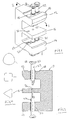
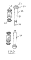
- FIG. 3 Upper and lower punches 22, 24 and guide bushings 28, 30 are shown.
- the pressing dies 22, 24 have a head 32, a shank 34 and a tool section 36. Only the tool portion 36 cooperates with the die bore 26 (hereinafter, only the upper punch 22 is treated, the lower punch 24 in the same way).
- the head 32 is substantially standardized in its top. He works in the Figures 1 and 2 Not shown pressure rollers together, which press the upper punch 22 into the die bore 26 against the press material.
- the shaft 34 is of non-circular cross-section.
- FIG. 4 Cross-sectional shapes are shown by way of example. They show a triangular, a square and a three-section circular cross-section, the transitions are rounded.
- the guide bushings 28, 30, which may consist of ceramic material and are glued into the receiving bores 18 and 20 respectively, have a cross-section of the shafts 34 complementary cross-section. The described cross sections therefore determine the rotational position of the punches 22, 24 in the punch guide 12 and 14, respectively.
- Each punch 22, 24 or each guide bush 28 and 30 is associated with an upper sealing ring 38 and a lower sealing ring 40.
- Fig. 6 At 60, the circumference of a pressure roller is indicated, under which the punch heads 32 are moved along, so that the punches 22 are pressed down into the die holes 26. As is particularly clear from this, the transition of the pressure roller circumference from one punch top to the next is almost uniform, so that only small impacts are generated, which lead to vibrations of the rotor.
Landscapes
- Engineering & Computer Science (AREA)
- Mechanical Engineering (AREA)
- Powder Metallurgy (AREA)
- Press Drives And Press Lines (AREA)
- Manufacture Of Motors, Generators (AREA)
- Processing And Handling Of Plastics And Other Materials For Molding In General (AREA)
- Encapsulation Of And Coatings For Semiconductor Or Solid State Devices (AREA)
Abstract
Description
- Die Erfindung bezieht sich auf einen Rotor für eine Rundlauf-Tablettenpresse nach dem Oberbegriff des Patentanspruchs 1.
- Der typische Rotor für eine Rundlaufpresse weist eine Matrizenscheibe sowie eine untere und eine obere Stempelführung für Unter- und Oberstempel auf, welche mit Bohrungen in der Matrizenscheibe zusammenwirken. Der Rotor wird von einem geeigneten Antriebsmotor um eine vertikale Achse angetrieben, und das von einer Fülleinrichtung in die Matrizenbohrungen eingefüllte pulverförmige Material wird von den Pressstempeln zusammengepresst. Das Verpressen geschieht in mindestens einer Druckstation, die eine obere und eine untere Druckrolle aufweist, die mit den Köpfen der Pressstempel zusammenwirken. In den übrigen Drehphasen werden die Pressstempel von geeigneten Stempelkurven geführt, unter anderem zum Ausstoßen der Presslinge durch die Unterstempel mit Hilfe entsprechender Steuerkurven. Derartige Rotoren sind aus
US 5 004 413 ,DE 101 59 114 A1 oderDE 10 2004 040 163 B3 bekannt geworden. - Der Abstand der Pressstempel untereinander, die auf einem Teilkreis im Rotor paarweise angeordnet sind, wird im Wesentlichen von dem Durchmesser der Stempelköpfe bestimmt. Die Oberseite der Pressstempelköpfe, mit der die Druckrollen zusammenwirken, ist im Wesentlichen standardisiert. Zwischen den Eingriffslinien auf den Stempelköpfen besteht ein nicht unerheblicher Abstand, der zur Folge hat, dass ein ungleichmäßiger Übergang der Druckrolle von einem zum nächsten Stempel stattfindet. Dadurch entwickelt sich eine erhebliche Geräuschemission. Außerdem wird dadurch der Verschleiß an Stempel und Druckrolle verursacht.
- Der Erfindung liegt die Aufgabe zugrunde, die ungünstige Wechselwirkung zwischen Druckrolle und Stempelkopf zu verringern und bei gleicher Druckhaltezeit Platz für die Anzahl von Pressstationen auf dem Teilkreis zu erhöhen, ohne den apparativen Aufwand für einen Pressenrotor zu erhöhen.
- Diese Aufgabe wird durch die Merkmale des Patentanspruchs 1 gelöst.
- Bei dem erfindungsgemäßen Rotor sind die Stempel gegen Drehung gesichert, d.h. sie werden ausschließlich axial in den Führungsbohrungen geführt. Eine axiale Führung ist jedoch an sich bekannt. Erfindungswesentlich ist jedoch, dass die Stempelköpfe auf gegenüberliegenden Seiten Abflachungen aufweisen, die zu den benachbarten Stempelköpfen hin gerichtet sind. Die Drehlage der Stempel, welche durch die ausschließliche Axialführung vorgegeben ist, ermöglicht mithin die Ausrichtung der Abflachungen an den Stempelköpfen zu den benachbarten Stempelköpfen hin.
- Mit der Erfindung wird der Vorteil erzielt, dass die Stempel auf einem Teilkreis enger zusammenliegen können und mithin einen geringeren Abstand voneinander aufweisen. Es ist daher möglich, mehr Stempelpaare auf einem Teilkreisdurchmesser anzuordnen. Dies ist im Hinblick auf den Produktionsausstoß von Vorteil, da mit dem gleichen Rotor bei gleicher Drehzahl eine größere Anzahl von Presslingen erzeugt werden kann als bei konventionellen Rotoren.
- Besonders vorteilhaft ist die günstigere Wechselwirkung zwischen Druckrolle und Stempelkopf durch den vergleichmäßigten Übergang der Druckrolle von einem Stempelkopf zum nächsten. Dadurch wird die Geräuschemission durch die geringeren Kraftschwankungen der Druckrolle kleiner. Ferner vermindert dies die Schwingungen der Rundlaufpresse. Schließlich wird auch der Verschleiß an den Stempeln und den Druckrollen reduziert.
- Es sind verschiedene Möglichkeiten denkbar, einen Stempel axial in den Führungsbohrungen des Rotors zu führen und gegen Verdrehen zu sichern. Dies kann beispielsweise dadurch geschehen, dass die Stempelschäfte eine Passfedernut aufweisen und die Führungsbohrungen eine Passfeder enthalten bzw. umgekehrt. Besonders vorteilhaft ist, wenn nach einer Ausgestaltung der Erfindung die Schäfte der Pressstempel im Querschnitt ein unrundes Profil aufweisen und der Querschnitt der Führungsbohrungen komplementär ist. Dadurch wird nicht nur eine Orientierung in Umfangsrichtung erhalten mit der gewünschten Lage der Abflachungen, sondern derartige Stempelschäfte lassen sich auch mit Hilfe geeigneter Dichtringe besser abdichten.
- Die Erfindung wird nachfolgend anhand von Zeichnungen näher erläutert.
-
Fig. 1 zeigt perspektivisch einen Ausschnitt von einem Rotor nach der Erfindung. -
Fig. 2 zeigt einen Schnitt durch die Darstellung nachFig. 1 entlang der Linie 2-2. -
Fig. 3 zeigt eine Explosionsdarstellung von einem Stempelpaar mit Gleitbuchsen und Dichtungen. -
Fig. 4 zeigt drei verschiedene Querschnittsprofile für die Pressstempel in denFign. 1 und 2 . -
Fig. 5 zeigt die Draufsicht auf mehrere Pressstempel einer sonst nicht weiter gezeigten Rundlaufpresse. -
Fig. 6 zeigt zwei benachbarte Pressstempel im Schnitt unter einer Druckrolle. -
Fig. 7 zeigt ebenfalls eine Draufsicht auf einen Pressstempelkopf. - Ein Rotor 10, von dem in
Fig. 1 lediglich ein Ausschnitt gezeigt ist, weist eine obere Stempelführung 12 und eine untere Stempelführung 14 auf sowie eine Matrizenscheibe 16 zwischen oberer und unterer Stempelführung 12, 14. Im gezeigten Fall sind alle Teile eine einteilige Einheit. Es versteht sich, dass sie auch mehrteilig sein kann. Insbesondere kann die Matrizenscheibe aus einzelnen Segmenten bestehen. - Die obere Stempelführung 12 weist Aufnahmebohrungen 18 auf, und die untere Stempelführung 14 weist Aufnahmebohrungen 20 auf. Die Stempelführungen 12, 14 führen paarweise Oberstempel 22 und Unterstempel 24, welche mit Matrizenbohrungen 26 der Matrizenscheibe 16 zusammenwirken, um pulverförmiges Material in den Matrizenbohrungen 26 zu verpressen.
- Wie insbesondere in
Fig. 2 zu erkennen, nehmen die Aufnahmebohrungen 18, 20 Führungsbuchsen 28, 30 auf. InFig. 3 sind Ober- und Unterstempel 22, 24 und Führungsbuchsen 28, 30 dargestellt. Die Pressstempel 22, 24 weisen einen Kopf 32, einen Schaft 34 und einen Werkzeugabschnitt 36 auf. Nur der Werkzeugabschnitt 36 wirkt mit der Matrizenbohrung 26 zusammen (nachfolgend wird nur der Oberstempel 22 behandelt, wobei der Unterstempel 24 in gleicher Weise zu betrachten ist). Der Kopf 32 ist in seiner Oberseite im Wesentlichen standardisiert. Er wirkt mit in denFiguren 1 und 2 nicht gezeigten Druckrollen zusammen, welche den Oberstempel 22 in die Matrizenbohrung 26 hinein gegen das Pressmaterial pressen. Der Schaft 34 ist von unrundem Querschnitt. - In
Fig. 4 sind Querschnittsformen beispielhaft dargestellt. Sie zeigen einen dreieckigen, einen quadratischen und einen aus drei Kreisabschnitten zusammengesetzten Querschnitt, wobei die Übergänge gerundet sind. Die Führungsbuchsen 28, 30, die aus keramischem Material bestehen können und in die Aufnahmebohrungen 18 bzw. 20 eingeklebt sind, haben einen zum Querschnitt der Schäfte 34 komplementären Querschnitt. Die beschriebenen Querschnitte legen daher die Drehlage der Stempel 22, 24 in der Stempelführung 12 bzw. 14 fest. Jedem Stempel 22, 24 bzw. jeder Führungsbuchse 28 bzw. 30 ist ein oberer Dichtring 38 und ein unterer Dichtring 40 zugeordnet. - Aus den
Figuren 1 und 2 geht auch hervor, dass die Stempelköpfe 32 an der Seite Abflachungen 56 haben, die jeweils benachbarten Stempelköpfen zugekehrt sind. In denFiguren 5 bis 7 sind die Abflachungen etwas deutlicher herausgestellt. Man erkennt, dass die Abflachungen nicht diametral einander gegenüberliegen bzw. parallel verlaufen, sondern sich annähernd senkrecht zur Tangente am Teilkreis 58 erstrecken, auf dem die Stempel 22 bzw. 24 im Rotor 10 angeordnet sind. Mithin konvergieren die Abflachungen 56 gemäßFig. 7 zur Mitte des Teilkreises, wie besonders deutlich inFig. 7 dargestellt. - In
Fig. 6 ist bei 60 der Umfang einer Druckrolle angedeutet, unter der die Stempelköpfe 32 entlang bewegt werden, damit die Stempel 22 nach unten in die Matrizenbohrungen 26 hineingedrückt werden. Wie hieraus besonders deutlich wird, ist der Übergang des Druckrollenumfangs von einer Stempeloberseite zur nächsten nahezu gleichmäßig, so dass nur geringe Stöße erzeugt werden, die zu Schwingungen des Rotors führen.
Claims (3)
- Rotor für eine Rundlauf-Tablettenpresse, der eine obere und eine untere Stempelführung für Ober- und Unterstempel aufweist, die mit Bohrungen einer zwischen Ober- und Unterstempelführung angeordneten Matrizenscheibe zusammenwirken, wobei die Stempel in Führungsbohrungen der Stempelführungen axial bewegbar sind und Köpfe aufweisen, mit denen Druckrollen der Tablettenpresse zusammenwirken, dadurch gekennzeichnet, dass die Pressstempel (22, 24) gegen Drehung gesichert in den Führungsbohrungen axial geführt sind und die Stempelköpfe (32) auf gegenüberliegenden Seiten Abflachungen (56) aufweisen, die zu den benachbarten Stempelköpfen (32) hin gerichtet sind.
- Rotor nach Anspruch 1, dadurch gekennzeichnet, dass die Schäfte der Pressstempel im Querschnitt ein unrundes Profil aufweisen und der Querschnitt der Führungsbohrungen komplementär ist.
- Rotor nach Anspruch 1 oder 2, dadurch gekennzeichnet, dass die Pressstempel (22, 24) auf einem Teilkreis (58) angeordnet sind und die Abflachungen (56) annähernd senkrecht zu dem Teilkreis (58) erstreckt sind.
Applications Claiming Priority (1)
| Application Number | Priority Date | Filing Date | Title |
|---|---|---|---|
| DE102007043582A DE102007043582B3 (de) | 2007-09-13 | 2007-09-13 | Rotor für eine Rundlauf-Tablettenpresse |
Publications (3)
| Publication Number | Publication Date |
|---|---|
| EP2036708A2 true EP2036708A2 (de) | 2009-03-18 |
| EP2036708A3 EP2036708A3 (de) | 2011-10-05 |
| EP2036708B1 EP2036708B1 (de) | 2013-07-31 |
Family
ID=39877456
Family Applications (1)
| Application Number | Title | Priority Date | Filing Date |
|---|---|---|---|
| EP08015747.2A Not-in-force EP2036708B1 (de) | 2007-09-13 | 2008-09-06 | Rotor für eine Rundlauf-Tablettenpresse |
Country Status (3)
| Country | Link |
|---|---|
| US (1) | US7824170B2 (de) |
| EP (1) | EP2036708B1 (de) |
| DE (1) | DE102007043582B3 (de) |
Families Citing this family (4)
| Publication number | Priority date | Publication date | Assignee | Title |
|---|---|---|---|---|
| GB2466963B (en) * | 2009-01-16 | 2011-01-19 | Holland Ltd I | A punch |
| DE102009031367B3 (de) | 2009-07-02 | 2010-09-02 | Fette Gmbh | Pressstempel für eine Rundläuferpresse |
| KR101552018B1 (ko) * | 2012-11-07 | 2015-09-09 | 오씨아이 주식회사 | 진공단열재 심재의 성형 장치 및 이를 통해 제조된 진공단열재 |
| DE102016113724B4 (de) * | 2016-07-26 | 2019-01-17 | Fette Compacting Gmbh | Stempel für eine Rundläuferpresse |
Family Cites Families (8)
| Publication number | Priority date | Publication date | Assignee | Title |
|---|---|---|---|---|
| US2068619A (en) * | 1935-09-13 | 1937-01-19 | Stokes Machine Co | Tablet-making machine |
| GB1137032A (en) * | 1965-07-28 | 1968-12-18 | United States Borax Chem | Process and apparatus for forming tablets |
| US4298563A (en) * | 1978-10-19 | 1981-11-03 | Ptx-Pentronix, Inc. | Apparatus and method for compacting prismatic or pyramidal articles from powder material |
| DE8815075U1 (de) * | 1988-12-03 | 1990-04-05 | Manesty Machines Ltd., Liverpool, Lancashire | Tablettiermaschine |
| JPH066147B2 (ja) * | 1991-08-08 | 1994-01-26 | 株式会社菊水製作所 | 回転式粉末成形機の杵 |
| DE10159114B4 (de) * | 2001-12-01 | 2004-02-19 | Wilhelm Fette Gmbh | Rotor für eine Tablettenpresse |
| JP3756863B2 (ja) * | 2002-09-27 | 2006-03-15 | 株式会社菊水製作所 | 回転式粉末圧縮成形機 |
| DE102004040163C5 (de) * | 2004-08-19 | 2009-06-18 | Fette Gmbh | Rundläufertablettenpresse |
-
2007
- 2007-09-13 DE DE102007043582A patent/DE102007043582B3/de not_active Expired - Fee Related
-
2008
- 2008-09-06 EP EP08015747.2A patent/EP2036708B1/de not_active Not-in-force
- 2008-09-11 US US12/208,909 patent/US7824170B2/en active Active
Also Published As
| Publication number | Publication date |
|---|---|
| EP2036708B1 (de) | 2013-07-31 |
| US7824170B2 (en) | 2010-11-02 |
| US20090252823A1 (en) | 2009-10-08 |
| EP2036708A3 (de) | 2011-10-05 |
| DE102007043582B3 (de) | 2008-11-27 |
Similar Documents
| Publication | Publication Date | Title |
|---|---|---|
| EP0418779B1 (de) | Verfahren zum Herstellen von Werkstücken durch Schneiden, insbesondere in einem Konterschneidwerkzeug | |
| DE2363948C2 (de) | Vorrichtung zum Formpressen schraubenförmiger bzw. schrägverzahnter Zahnräder mit verschiedenen Zahnungen | |
| EP0667197B1 (de) | Schmiedemaschine | |
| EP2036708B1 (de) | Rotor für eine Rundlauf-Tablettenpresse | |
| DE3140630C2 (de) | Spikeplatte und Verfahren zur Herstellung sowie Einrichtung zum Zähnen von Spikeplatten | |
| EP2082867B1 (de) | Tablettenpresse | |
| DE10260110B4 (de) | Vorrichtung zum Stanzen | |
| EP2036710B1 (de) | Rotor für eine Rundlauf-Tablettenpresse | |
| CH710828B1 (de) | Pulverpresse sowie ein Futtergehäuse mit vorzugsweise mehreren für ein Querpressen verschiebbaren Stempeln. | |
| DE10024340C2 (de) | Stempel für Rundlaufpresse | |
| WO2015039750A1 (de) | Vorrichtung zum rotationsstanzen | |
| EP3275639B1 (de) | Stempel für eine rundläuferpresse | |
| EP1452301A2 (de) | Kniehebelpresse | |
| EP1764173B1 (de) | Vorrichtung zum Herstellen eines Formteils | |
| DE102006046147B4 (de) | Presseneinheit für eine Fertigholzproduktpresse | |
| EP2269813B1 (de) | Pressstempel für eine Rundläuferpresse | |
| DE102006046143B4 (de) | Kombinierte Zeitsteuerungs- und Verkettungsbaueinheit für eine Fertigholzproduktpresse | |
| EP4279257B1 (de) | Tablettierwerkzeug | |
| DE102009016781B3 (de) | Stempel für eine Rundläuferpresse und Vorrichtung zum Montieren und Demontieren von Stempeleinsätzen für Stempel in einer Rundläuferpresse | |
| EP3095534B1 (de) | Biegemaschine | |
| EP1658962B1 (de) | Mehrstufenpresse | |
| DE2402190B2 (de) | Vorrichtung zum biegen von stahlblechen bzw. -platten | |
| DE102016108673A1 (de) | Presse zum Herstellen von Feinschneidteilen | |
| EP3517289A1 (de) | Verstellbare vordruckschiene für rundlaufpresse mit integrierter messung der vordruckkraft | |
| DE19620597C2 (de) | Vorrichtung zur Bearbeitung von Lagenmaterial |
Legal Events
| Date | Code | Title | Description |
|---|---|---|---|
| PUAI | Public reference made under article 153(3) epc to a published international application that has entered the european phase |
Free format text: ORIGINAL CODE: 0009012 |
|
| AK | Designated contracting states |
Kind code of ref document: A2 Designated state(s): AT BE BG CH CY CZ DE DK EE ES FI FR GB GR HR HU IE IS IT LI LT LU LV MC MT NL NO PL PT RO SE SI SK TR |
|
| AX | Request for extension of the european patent |
Extension state: AL BA MK RS |
|
| PUAL | Search report despatched |
Free format text: ORIGINAL CODE: 0009013 |
|
| AK | Designated contracting states |
Kind code of ref document: A3 Designated state(s): AT BE BG CH CY CZ DE DK EE ES FI FR GB GR HR HU IE IS IT LI LT LU LV MC MT NL NO PL PT RO SE SI SK TR |
|
| AX | Request for extension of the european patent |
Extension state: AL BA MK RS |
|
| RIC1 | Information provided on ipc code assigned before grant |
Ipc: B30B 15/06 20060101ALI20110901BHEP Ipc: B30B 11/08 20060101AFI20110901BHEP Ipc: B30B 15/04 20060101ALI20110901BHEP |
|
| 17P | Request for examination filed |
Effective date: 20120214 |
|
| AKX | Designation fees paid |
Designated state(s): AT BE BG CH CY CZ DE DK EE ES FI FR GB GR HR HU IE IS IT LI LT LU LV MC MT NL NO PL PT RO SE SI SK TR |
|
| GRAP | Despatch of communication of intention to grant a patent |
Free format text: ORIGINAL CODE: EPIDOSNIGR1 |
|
| INTG | Intention to grant announced |
Effective date: 20130328 |
|
| GRAS | Grant fee paid |
Free format text: ORIGINAL CODE: EPIDOSNIGR3 |
|
| GRAA | (expected) grant |
Free format text: ORIGINAL CODE: 0009210 |
|
| AK | Designated contracting states |
Kind code of ref document: B1 Designated state(s): AT BE BG CH CY CZ DE DK EE ES FI FR GB GR HR HU IE IS IT LI LT LU LV MC MT NL NO PL PT RO SE SI SK TR |
|
| REG | Reference to a national code |
Ref country code: CH Ref legal event code: EP Ref country code: GB Ref legal event code: FG4D Free format text: NOT ENGLISH Ref country code: CH Ref legal event code: NV Representative=s name: ISLER AND PEDRAZZINI AG, CH |
|
| REG | Reference to a national code |
Ref country code: AT Ref legal event code: REF Ref document number: 624352 Country of ref document: AT Kind code of ref document: T Effective date: 20130815 |
|
| REG | Reference to a national code |
Ref country code: IE Ref legal event code: FG4D Free format text: LANGUAGE OF EP DOCUMENT: GERMAN |
|
| REG | Reference to a national code |
Ref country code: DE Ref legal event code: R096 Ref document number: 502008010394 Country of ref document: DE Effective date: 20130926 |
|
| REG | Reference to a national code |
Ref country code: NL Ref legal event code: VDEP Effective date: 20130731 |
|
| REG | Reference to a national code |
Ref country code: LT Ref legal event code: MG4D |
|
| PG25 | Lapsed in a contracting state [announced via postgrant information from national office to epo] |
Ref country code: IS Free format text: LAPSE BECAUSE OF FAILURE TO SUBMIT A TRANSLATION OF THE DESCRIPTION OR TO PAY THE FEE WITHIN THE PRESCRIBED TIME-LIMIT Effective date: 20131130 Ref country code: NO Free format text: LAPSE BECAUSE OF FAILURE TO SUBMIT A TRANSLATION OF THE DESCRIPTION OR TO PAY THE FEE WITHIN THE PRESCRIBED TIME-LIMIT Effective date: 20131031 Ref country code: SE Free format text: LAPSE BECAUSE OF FAILURE TO SUBMIT A TRANSLATION OF THE DESCRIPTION OR TO PAY THE FEE WITHIN THE PRESCRIBED TIME-LIMIT Effective date: 20130731 Ref country code: HR Free format text: LAPSE BECAUSE OF FAILURE TO SUBMIT A TRANSLATION OF THE DESCRIPTION OR TO PAY THE FEE WITHIN THE PRESCRIBED TIME-LIMIT Effective date: 20130731 Ref country code: LT Free format text: LAPSE BECAUSE OF FAILURE TO SUBMIT A TRANSLATION OF THE DESCRIPTION OR TO PAY THE FEE WITHIN THE PRESCRIBED TIME-LIMIT Effective date: 20130731 Ref country code: PT Free format text: LAPSE BECAUSE OF FAILURE TO SUBMIT A TRANSLATION OF THE DESCRIPTION OR TO PAY THE FEE WITHIN THE PRESCRIBED TIME-LIMIT Effective date: 20131202 Ref country code: CY Free format text: LAPSE BECAUSE OF FAILURE TO SUBMIT A TRANSLATION OF THE DESCRIPTION OR TO PAY THE FEE WITHIN THE PRESCRIBED TIME-LIMIT Effective date: 20130724 |
|
| PG25 | Lapsed in a contracting state [announced via postgrant information from national office to epo] |
Ref country code: LV Free format text: LAPSE BECAUSE OF FAILURE TO SUBMIT A TRANSLATION OF THE DESCRIPTION OR TO PAY THE FEE WITHIN THE PRESCRIBED TIME-LIMIT Effective date: 20130731 Ref country code: SI Free format text: LAPSE BECAUSE OF FAILURE TO SUBMIT A TRANSLATION OF THE DESCRIPTION OR TO PAY THE FEE WITHIN THE PRESCRIBED TIME-LIMIT Effective date: 20130731 Ref country code: GR Free format text: LAPSE BECAUSE OF FAILURE TO SUBMIT A TRANSLATION OF THE DESCRIPTION OR TO PAY THE FEE WITHIN THE PRESCRIBED TIME-LIMIT Effective date: 20131101 Ref country code: FI Free format text: LAPSE BECAUSE OF FAILURE TO SUBMIT A TRANSLATION OF THE DESCRIPTION OR TO PAY THE FEE WITHIN THE PRESCRIBED TIME-LIMIT Effective date: 20130731 Ref country code: PL Free format text: LAPSE BECAUSE OF FAILURE TO SUBMIT A TRANSLATION OF THE DESCRIPTION OR TO PAY THE FEE WITHIN THE PRESCRIBED TIME-LIMIT Effective date: 20130731 Ref country code: NL Free format text: LAPSE BECAUSE OF FAILURE TO SUBMIT A TRANSLATION OF THE DESCRIPTION OR TO PAY THE FEE WITHIN THE PRESCRIBED TIME-LIMIT Effective date: 20130731 |
|
| PG25 | Lapsed in a contracting state [announced via postgrant information from national office to epo] |
Ref country code: CY Free format text: LAPSE BECAUSE OF FAILURE TO SUBMIT A TRANSLATION OF THE DESCRIPTION OR TO PAY THE FEE WITHIN THE PRESCRIBED TIME-LIMIT Effective date: 20130731 |
|
| PG25 | Lapsed in a contracting state [announced via postgrant information from national office to epo] |
Ref country code: RO Free format text: LAPSE BECAUSE OF FAILURE TO SUBMIT A TRANSLATION OF THE DESCRIPTION OR TO PAY THE FEE WITHIN THE PRESCRIBED TIME-LIMIT Effective date: 20130731 Ref country code: DK Free format text: LAPSE BECAUSE OF FAILURE TO SUBMIT A TRANSLATION OF THE DESCRIPTION OR TO PAY THE FEE WITHIN THE PRESCRIBED TIME-LIMIT Effective date: 20130731 Ref country code: EE Free format text: LAPSE BECAUSE OF FAILURE TO SUBMIT A TRANSLATION OF THE DESCRIPTION OR TO PAY THE FEE WITHIN THE PRESCRIBED TIME-LIMIT Effective date: 20130731 Ref country code: MC Free format text: LAPSE BECAUSE OF FAILURE TO SUBMIT A TRANSLATION OF THE DESCRIPTION OR TO PAY THE FEE WITHIN THE PRESCRIBED TIME-LIMIT Effective date: 20130731 Ref country code: SK Free format text: LAPSE BECAUSE OF FAILURE TO SUBMIT A TRANSLATION OF THE DESCRIPTION OR TO PAY THE FEE WITHIN THE PRESCRIBED TIME-LIMIT Effective date: 20130731 Ref country code: CZ Free format text: LAPSE BECAUSE OF FAILURE TO SUBMIT A TRANSLATION OF THE DESCRIPTION OR TO PAY THE FEE WITHIN THE PRESCRIBED TIME-LIMIT Effective date: 20130731 |
|
| PG25 | Lapsed in a contracting state [announced via postgrant information from national office to epo] |
Ref country code: ES Free format text: LAPSE BECAUSE OF FAILURE TO SUBMIT A TRANSLATION OF THE DESCRIPTION OR TO PAY THE FEE WITHIN THE PRESCRIBED TIME-LIMIT Effective date: 20130731 |
|
| PLBE | No opposition filed within time limit |
Free format text: ORIGINAL CODE: 0009261 |
|
| STAA | Information on the status of an ep patent application or granted ep patent |
Free format text: STATUS: NO OPPOSITION FILED WITHIN TIME LIMIT |
|
| REG | Reference to a national code |
Ref country code: IE Ref legal event code: MM4A |
|
| 26N | No opposition filed |
Effective date: 20140502 |
|
| PG25 | Lapsed in a contracting state [announced via postgrant information from national office to epo] |
Ref country code: IE Free format text: LAPSE BECAUSE OF NON-PAYMENT OF DUE FEES Effective date: 20130906 |
|
| REG | Reference to a national code |
Ref country code: DE Ref legal event code: R097 Ref document number: 502008010394 Country of ref document: DE Effective date: 20140502 |
|
| REG | Reference to a national code |
Ref country code: AT Ref legal event code: MM01 Ref document number: 624352 Country of ref document: AT Kind code of ref document: T Effective date: 20130906 |
|
| PG25 | Lapsed in a contracting state [announced via postgrant information from national office to epo] |
Ref country code: AT Free format text: LAPSE BECAUSE OF NON-PAYMENT OF DUE FEES Effective date: 20130906 |
|
| PG25 | Lapsed in a contracting state [announced via postgrant information from national office to epo] |
Ref country code: MT Free format text: LAPSE BECAUSE OF FAILURE TO SUBMIT A TRANSLATION OF THE DESCRIPTION OR TO PAY THE FEE WITHIN THE PRESCRIBED TIME-LIMIT Effective date: 20130731 Ref country code: TR Free format text: LAPSE BECAUSE OF FAILURE TO SUBMIT A TRANSLATION OF THE DESCRIPTION OR TO PAY THE FEE WITHIN THE PRESCRIBED TIME-LIMIT Effective date: 20130731 |
|
| PG25 | Lapsed in a contracting state [announced via postgrant information from national office to epo] |
Ref country code: BG Free format text: LAPSE BECAUSE OF FAILURE TO SUBMIT A TRANSLATION OF THE DESCRIPTION OR TO PAY THE FEE WITHIN THE PRESCRIBED TIME-LIMIT Effective date: 20130731 Ref country code: HU Free format text: LAPSE BECAUSE OF FAILURE TO SUBMIT A TRANSLATION OF THE DESCRIPTION OR TO PAY THE FEE WITHIN THE PRESCRIBED TIME-LIMIT; INVALID AB INITIO Effective date: 20080906 Ref country code: LU Free format text: LAPSE BECAUSE OF NON-PAYMENT OF DUE FEES Effective date: 20130906 |
|
| REG | Reference to a national code |
Ref country code: FR Ref legal event code: PLFP Year of fee payment: 9 |
|
| REG | Reference to a national code |
Ref country code: FR Ref legal event code: PLFP Year of fee payment: 10 |
|
| REG | Reference to a national code |
Ref country code: FR Ref legal event code: PLFP Year of fee payment: 11 |
|
| PGFP | Annual fee paid to national office [announced via postgrant information from national office to epo] |
Ref country code: FR Payment date: 20210927 Year of fee payment: 14 Ref country code: CH Payment date: 20210923 Year of fee payment: 14 Ref country code: IT Payment date: 20210930 Year of fee payment: 14 |
|
| PGFP | Annual fee paid to national office [announced via postgrant information from national office to epo] |
Ref country code: BE Payment date: 20210921 Year of fee payment: 14 Ref country code: GB Payment date: 20210923 Year of fee payment: 14 |
|
| PGFP | Annual fee paid to national office [announced via postgrant information from national office to epo] |
Ref country code: DE Payment date: 20211116 Year of fee payment: 14 |
|
| REG | Reference to a national code |
Ref country code: DE Ref legal event code: R119 Ref document number: 502008010394 Country of ref document: DE |
|
| REG | Reference to a national code |
Ref country code: CH Ref legal event code: PL |
|
| GBPC | Gb: european patent ceased through non-payment of renewal fee |
Effective date: 20220906 |
|
| REG | Reference to a national code |
Ref country code: BE Ref legal event code: MM Effective date: 20220930 |
|
| PG25 | Lapsed in a contracting state [announced via postgrant information from national office to epo] |
Ref country code: LI Free format text: LAPSE BECAUSE OF NON-PAYMENT OF DUE FEES Effective date: 20220930 Ref country code: FR Free format text: LAPSE BECAUSE OF NON-PAYMENT OF DUE FEES Effective date: 20220930 Ref country code: DE Free format text: LAPSE BECAUSE OF NON-PAYMENT OF DUE FEES Effective date: 20230401 Ref country code: CH Free format text: LAPSE BECAUSE OF NON-PAYMENT OF DUE FEES Effective date: 20220930 |
|
| PG25 | Lapsed in a contracting state [announced via postgrant information from national office to epo] |
Ref country code: BE Free format text: LAPSE BECAUSE OF NON-PAYMENT OF DUE FEES Effective date: 20220930 |
|
| PG25 | Lapsed in a contracting state [announced via postgrant information from national office to epo] |
Ref country code: IT Free format text: LAPSE BECAUSE OF NON-PAYMENT OF DUE FEES Effective date: 20220906 Ref country code: GB Free format text: LAPSE BECAUSE OF NON-PAYMENT OF DUE FEES Effective date: 20220906 |