EP2036728B1 - Presse rotative d'impression dotée d'au moins une unité d'impression émettant un bruit gênant - Google Patents
Presse rotative d'impression dotée d'au moins une unité d'impression émettant un bruit gênant Download PDFInfo
- Publication number
- EP2036728B1 EP2036728B1 EP08162322A EP08162322A EP2036728B1 EP 2036728 B1 EP2036728 B1 EP 2036728B1 EP 08162322 A EP08162322 A EP 08162322A EP 08162322 A EP08162322 A EP 08162322A EP 2036728 B1 EP2036728 B1 EP 2036728B1
- Authority
- EP
- European Patent Office
- Prior art keywords
- printing
- printing unit
- forme
- noise protection
- protection element
- Prior art date
- Legal status (The legal status is an assumption and is not a legal conclusion. Google has not performed a legal analysis and makes no representation as to the accuracy of the status listed.)
- Not-in-force
Links
Images


Classifications
-
- B—PERFORMING OPERATIONS; TRANSPORTING
- B41—PRINTING; LINING MACHINES; TYPEWRITERS; STAMPS
- B41F—PRINTING MACHINES OR PRESSES
- B41F27/00—Devices for attaching printing elements or formes to supports
- B41F27/12—Devices for attaching printing elements or formes to supports for attaching flexible printing formes
- B41F27/1206—Feeding to or removing from the forme cylinder
-
- B—PERFORMING OPERATIONS; TRANSPORTING
- B41—PRINTING; LINING MACHINES; TYPEWRITERS; STAMPS
- B41F—PRINTING MACHINES OR PRESSES
- B41F13/00—Common details of rotary presses or machines
- B41F13/08—Cylinders
- B41F13/42—Guards or covers, e.g. for preventing ingress or egress of foreign matter
-
- B—PERFORMING OPERATIONS; TRANSPORTING
- B41—PRINTING; LINING MACHINES; TYPEWRITERS; STAMPS
- B41P—INDEXING SCHEME RELATING TO PRINTING, LINING MACHINES, TYPEWRITERS, AND TO STAMPS
- B41P2251/00—Details or accessories of printing machines not otherwise provided for
Definitions
- the invention relates to a rotary printing press with at least one noise-emitting pressure unit according to the preamble of claim 1.
- the human ear usually perceives sound in a frequency range of 16 Hz to 20 kHz.
- Noise refers to a sound that affects a person's intentional sound pickup or the perception of a sound event.
- a work machine such. B. on a rotary printing machine can be caused by background noise increased accident risk by covering of audible warning signals.
- B a mental performance
- a thinking achievement eg. B. a thinking achievement.
- For the frequency evaluation which takes into account the fact that the human ear perceives sounds with the same sound pressure at different pitches differently loud, it is common practice to use a physically measured sound pressure level with one of the standardized filters with the Name A, B, C or D to evaluate. In the case of continuous noise effects with A-weighted sound pressure levels above 85 dB (A), human hearing is endangered.
- noises of this intensity are present for a longer period of time on a human, hearing loss can be expected. Even one-off noise events with high A-weighted sound pressure levels above 120 dB (A) can directly damage your hearing. At even higher sound pressure levels of about 135 dB (A), an acute acoustic trauma can be triggered.
- a noise-emitting printing unit of a rotary printing machine with at least two forme cylinders wherein at least between these two cylinders form a plurality of noise protection elements are arranged.
- These noise protection elements each extending over the full width between opposing walls of the printing unit, form a contiguous area to the outside of the printing unit and leave a closed soundproofing arise, which a printing unit together with the respective forme cylinder associated inking and dampening completely against one of the outside of the printing unit accessible, decoupled for a to be carried out on the respective forme cylinder printing plate change operating room decoupled.
- the soundproofing has at least one door which is provided with a Schalldämmausposed, wherein the door has a left and a right vertical pivot axis, wherein the pivot axis function of the left and right pivot axis is selectively canceled.
- the control room belonging to the rotary printing press in a soundproofing room in order to generate an interference sound emitted by its at least one printing unit during a production of the rotary printing press at the workplace of this rotary printing press operating personnel below each one for this workstation z. B. legally and / or authorities on the one hand set limit value.
- Such applicable for printing machines limits are z. B. in the EC "noise" Directive 2003/10 EC, according to which z.
- the guideline value is an A-weighted sound pressure level of 83 dB (A) determined in accordance with EN ISO 11204. Under the condition that the printing cylinder z. B.
- the noise emitted by an uninsulated printing unit of an offset rotary printing press in a running printing process is generally distributed over the entire audible frequency spectrum for humans, the sound pressure level in the frequency range from 60 Hz to 20,000 Hz is generally consistently above 60 dB (A) , in the frequency range from 400 Hz to 8,000 Hz, generally even above 80 dB (A). The requirement for a reduction of the emitted noise is thus immediately apparent.
- the invention has for its object to provide a rotary printing machine with at least one noise-emitting pressure unit, wherein while maintaining the sound insulation arranging at least one printing plate on a plate cylinder of this printing unit is possible without hindrance.
- the achievable with the present invention consist in particular that under Maintaining the sound insulation z.
- this printing unit is possible without hindrance.
- an essential source of interference noise emitted by a printing unit is effectively contained by sound-absorbing at least partial enclosure of the printing units associated with that printing unit, while maintaining a largely unobstructed accessibility to the printing unit for the staff operating this rotary printing machine.
- a forme cylinder of a printing unit of the printing unit associated essential functional elements such.
- a paint tray and / or a printing forme magazine directly and freely, ie accessible barrier-free, which simplifies the operation and / or testing of these functional elements.
- Fig. 1 shows by way of example in a side view a preferably printing in an offset printing process rotary printing machine, in particular a web-fed rotary printing press, with a z. B.
- the paper web 03 may be deflected both at its inlet into the printing unit 01 and at its outlet from the printing unit 01 each by a guide roller 04 from their in the printing unit 01 substantially vertically oriented web guide.
- a running direction of the paper web 03 by the printing unit 01 thus results from the inlet of the paper web 03 in the printing unit 01 to the outlet of the printing unit 01st
- the printing unit 01 can be two printing unit halves 06; 07, which are arranged in each case to one of the two sides of the printing unit 01 continuous paper web 03, of which at least one, z. B. in the Fig. 1 shown on the right Printing unit half 07, in one of the printing unit halves 06; 07 enclosing machine frame 08 is movable, in particular arranged to be movable, so that in an operating state of the printing unit 01 both printing unit halves 06; 07 are employed on the paper web 03 and in another operating state of the printing unit 01 at least one of these printing unit halves 06; 07 is turned off by the paper web 03, which is in the Fig. 1 is indicated by acting on the right pressure unit half 07, pointing to the right arrow.
- Each one in the Fig. 1 illustrated printing units 02 of this printing unit 01 each has a printing cylinder 09; 11 a forme cylinder 09 and a cooperating with this forme cylinder 09 transfer cylinder 11, wherein the respective transfer cylinder 11 of two on different sides of the printing unit 01 continuous paper web 03 arranged printing units 02 against each other and in which in the Fig. 1 shown operating state of the printing unit 01 are each employed to form a pressure point against each other to print the guided between them through the paper web 03 in a production process of the printing unit 01 on both sides.
- Each transfer cylinder 11 of one of the printing units 02 thus forms an impression cylinder for the printing unit 02 arranged in the printing unit 01 at approximately the same height on the other side of the paper web 03.
- the printing unit 01 faces on both sides through the printing unit 01 guided printing material 03 each have at least three forme 09 on.
- the inking unit 12 is z. B. formed as a short inking unit 12 with an anilox roller 14.
- the ink reservoir 13 may be formed as a color trough 13.
- the printing cylinder 09; 11 are z. B. as a double-circumference printing cylinder 09; 11 formed so that on a lateral surface 39 of the forme cylinder 09 in the circumferential direction z. B. one behind the other two printing plates 37 ( Fig. 3 ) can be arranged.
- On the lateral surface 39 of the forme cylinder 09 are in the axial direction in each case z. B. four or six printing plates 37 next to each other can be arranged, so that the forme cylinder 09 z. B. is referred to as a 4/2 or 6/2 forme cylinder 09.
- Other occupation variants of the lateral surface 39 of the forme cylinder 09 with printing plates 37 are readily possible.
- each forme cylinder 09 of the printing unit 01 when the respective forme cylinder 09 of the printing unit 01 are assignable with a larger number of printing plates 37, which are often to change, as it is z. B. is common in newspaper printing, it is recommended that in the printing unit 01 in association with each forme cylinder 09 each provide a preferably remotely controllable printing forme magazine 16, in which preferably several printing plates 37 can be stored and with which an automated expiring change of printing plates 37 to the respective Form cylinder 09 by a in a control unit, for. B. a belonging to the printing unit 01 control station, implemented control is executable.
- printing unit 01 shown by way of example is attached to each forme cylinder 09 in each case a substantially horizontally oriented printing form magazine 16 tangentially.
- the arrangement of the printing cylinder 09; 11, the inking units 12 and the printing forme magazines 16 is in the in the Fig. 1
- the printing unit 01 shown by way of example is essentially symmetrical with respect to the paper web 03 passing through this printing unit 01.
- each inking unit 12 and the respective printing forme magazine 16 of each printing unit 02 is freely accessible from an operating side 38 of the printing unit 01 for the printing unit 01 serving staff, with the operator side 38 of the printing unit 01 on the side remote from the paper web 03 side respective printing units 02 is located.
- On the operating side 38 of each of the printing unit halves 06; 07 of the printing unit 01 can each one with the respective Printing unit half 06; 07 connected gallery 36, wherein the printing unit 01 serving staff from the respective gallery 36 of z. B. the respective inking units 12 and / or printing forme magazines 16 served.
- the respective gallery 36 can at their respective printing unit half 06; 07, ie along the height thereof, be designed adjustable in height, so that the staff of each of the inking units 12 and / or printing forme magazines 16 can easily reach and / or view.
- the printing cylinder 09; 11 have a diameter D09; D11 ( Fig. 3 ) z. B. in the range of 250 mm and 350 mm, preferably 270 mm to 320 mm, in particular about 300 mm. Their length is z. B. between 1,000 mm and 2,600 mm, preferably 1,700 mm to 2,400 mm. Printing cylinder 09; 11 of this size tend to generate vibrations during their rotation, thereby emitting background noise to a considerable extent.
- the in the Fig. 1 exemplified printing unit 01 imprints the guided through it paper web 03 z. B. in a dry offset printing process, ie no dampening solution is used in the printing process. Should the paper web 03 alternatively be printed in a damp offset wet offset printing process, each of the printing units 02 of this printing unit 01 is still equipped with a dampening solution for each forme cylinder 09 transporting dampening unit (not shown).
- an aeration device (not shown) is provided in an inner region 24 of the printing unit 01, which in the inner region 24 of the printing unit 01 existing, in particular jammed there, by the dampening agent there formed air moisture from the inner region 24 of the printing unit 01st z. B. by convection.
- the printing units 02 involved in the printing process emit a z. B. according to EN ISO 3744 or according to EN ISO 3746 determinable sound power level z. B. in the range of 90 dB (A) to 120 dB (A), which is to be reduced for the reasons outlined.
- At least one planar noise protection element 17 within the printing unit 01, preferably such that at least one of the noise protection elements 17 is arranged in the printing unit 01 between two forme cylinders 09, these two forme cylinders 09 are arranged either on the same side of the guided by the printing unit 01 web 03 and adjacent printing units 02 belonging to this printing unit 01 or wherein the forme cylinder 09 are arranged on opposite sides of the guided by the printing unit 01 paper web 03 and thus z. B. different printing unit halves 06; 07 belong.
- the arranged between these two cylinders 09 form at least one noise protection element 17, of course, a z. B. in the form of a preferably slot-shaped opening 21 (FIG. Fig.
- the arrangement of the at least one noise protection element 17 between two forme cylinders 09 means that this at least one noise protection element 17 extends from the jacket surface 39 of one forme cylinder 09 to the jacket surface 39 of the other forme cylinder 09, wherein this extension does not necessarily have to run along a straight line, but can also take a curved or provided with at least one bend course. If the at least one noise protection element 17 is arranged between two forming cylinders 09 which are arranged on opposite sides of the paper web 03 guided by the printing unit 01, a sound-absorbing cladding or housing can also be arranged for two against each other by a parallel arrangement of two of these noise protection elements 17 employed printing units 02 realize.
- the printing unit 01 two separate and / or separable printing unit halves 06; 07, the form cylinder 09, between which the at least one noise protection element 17 is arranged, either in the same pressure unit half 06; 07 arranged or it is one of the forme cylinder 09, between which the at least one noise protection element 17 is arranged, arranged in the one printing unit half 06 and the other forme cylinder 09 in the other printing unit half 07.
- At least one planar noise protection element 17 is arranged between all of the paper webs 03 arranged adjacent to the same side on the same side.
- z. B. lowermost on the same side of the paper web 03 lined-up form cylinder 09 is preferably at least one noise protection element 17 between this plate cylinder 09 and a bottom plate 18 of the printing unit 01 is arranged.
- z. B. top of the same side of the paper web 03 lined-up form cylinder 09 each have at least one noise protection element 17 between this form cylinder 09 and a ceiling plate 19 of the printing unit 01 may be arranged.
- both the bottom plate 18 of the printing unit 01 and the cover plate 19 may each be lined with at least one noise protection element 17, wherein for the inlet of the usually unprinted paper web 03 in the printing unit 01 and for the outlet of the preferably printed paper web 03 from the printing unit 01 is formed in each case a slot-shaped opening 21 in the bottom plate 18 and in the ceiling plate 19 together with the respectively attached to them noise protection elements 17.
- the sum of all disposed within the printing unit 01 noise protection elements 17 result within the printing unit 01 in itself at least almost closed sound insulation, once from slot-shaped openings 21 to the inlet and outlet of the paper web 03 in or out of the printing unit 01 and optionally of columns 29th ( Fig. 3 ) between the respective noise protection elements 17 and the lateral surface of the respective forme cylinder 09.
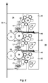
- Fig. 2 shows in a magnification a section of the in the Fig. 1 in a side view illustrated printing unit 01.
- said noise protection element 17th z. B. is preferably detachably and / or pivotally mounted on an axially extending to the respective form cylinders 09 crossbar 22.
- the crossbar 22 may, for. B. also be used as a cable channel.
- In or directly on at least one of the noise protection elements 17, preferably in or on several noise protection elements 17, z. B. a z. B. designed as a fluorescent tube light 23 may be integrated, which light z. B. in the inner region 24 of the printing unit 01 and / or in the direction of the inking unit 12 and / or in the direction of the printing forme magazine 16 radiates.
- Fig. 3 shows a further enlargement of the in the Fig. 2 in a side view section shown from the printing unit 01.
- a z. B. Siliconkasteter soundproofing body 26 attached to which then the actual noise protection element 17 z. B. hanging and hinged is attached.
- the noise protection element 17 has z. B. a thickness a17 in the range between 50 mm and 100 mm and is thus narrower than a diameter D09 of that forme cylinder 09, which is associated with the relevant noise protection element 17.
- the noise protection element 17 may have the function of a finger guard with respect to a rotating forme cylinder 09.
- At least one cooperating with one of the forme cylinder 09 pressing device 27 is provided, with an organ 28 of the respective Andschreib sensory 27 at least one arranged on the forme cylinder 09 or to be arranged printing plate 37 is pressed against a lateral surface 39 of the respective forme cylinder 09, wherein the member 28 of the pressing device 27 either between the noise protection element 17 and the relevant forme cylinder 09 or on the respective operating side 38 of the printing unit 01 is arranged at a distance a28 of less than a diameter D09 of the relevant forme cylinder 09 in front of the noise protection element 17.
- the pressing device 27 can be used as a in the axial direction of the forme cylinder 09 z. B. over its entire length extending Andschreibological 27 may be formed, wherein preferably with a z.
- the pressing device 27 is provided for the manual arrangement of at least one printing plate 37 on the lateral surface 39 of the relevant forme cylinder 09.
- the pressing device 27 cooperates with a forme cylinder 09 associated printing plate magazine 16, wherein the pressing device 27 z. B. is arranged integrated in the relevant printing forme magazine 16.
- the pressing device 27 may also be formed integrally in the noise protection element 17.
- At least the noise protection element 17 and the pressing device 27 can be formed as a single assembly, in which assembly, if necessary, the lamp 23 is arranged integrated.
- This z. B. the aforementioned functional elements in the same assembly integrating design leads to cost advantages in manufacturing and assembly and also allows a very compact design of the printing unit 01.
- the integrating design is particularly suitable for a very compact pressure unit 01, as in the Fig. 1 represented, since in such a pressure unit 01, the space for the arrangement of functional elements is very limited.
- Both the soundproofing body 26 and the noise protection element 17 form for the respective lateral surface 39 of at least one of the forme cylinder 09 z.
- a gap height s29 of this gap 29, measured between an end face of the soundproofing body 26 or the noise protection element 17 and the jacket surface 39 of at least one of the forme cylinders 09, is z.
- the respective gap 29 can also by a to the lateral surface 39 of the respective forme cylinder 09 extending elastic, z. B. formed in the form of a brush strip sealing lip (not shown) to be sealed against penetrating out of the inner region 24 of the printing unit 01 sound.
- the soundproofing body 26 and / or the noise protection element 17 are each z. B. as mats or plates each z. B. formed from an airborne sound absorbing foam, these mats or plates each on a z. B. metallic support surface z. B. may be applied by gluing.
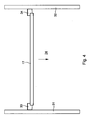
- Fig. 4 shows in a plan view between two opposing walls 31; 32 of the machine frame 08 arranged noise protection element 17, wherein the noise protection element 17 in the axial direction of the printing cylinder 09; 11 of a arranged in the printing unit 01 printing unit 02 extends.
- the noise protection element 17 is on both walls 31; 32 of the machine frame 08 each z. B. preferably with sound-insulated brackets 33; 34 preferably releasably connected, wherein the noise protection element 17 on these brackets 33; 34 z. B. mounted or screwed or locked, with sound-insulated brackets 33; 34 prevent transmission of structure-borne noise from the relevant machine frame 08 or to the relevant machine frame 08.
- a latching connection can by stop bolts and / or a spring element, for. B.
- the noise protection element 17 is z. B. in the direction of the inner region 24 of the printing unit 01 movable, z. B. hinged or hinged, resulting in the Fig. 4 indicated by a directional arrow.
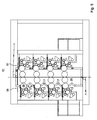
- Fig. 5 again shows the printing unit 01 of Fig. 1 , some of which are each arranged between adjacent cylinders 09 of different printing units 02
- Noise protection elements 17 are shown in the direction of the inner region 24 of the printing unit 01 in a folded position, ie at least some of the noise protection elements 17 are hinged.
- the noise protection elements 17 are formed foldable similar to a Faltrollo.
- the respective Nippstelle between the transfer cylinder 11 and cooperating with this transfer cylinder 11 impression cylinder which in turn may be formed as a transfer cylinder 11, which, however, belongs to another printing unit 02, the actual print substrate 03 effective pressure point wherein the forme cylinder 09 cooperating with the first-mentioned transfer cylinder 11 provides at least one printed image to be printed at the printing location.
- the actual print substrate 03 effective pressure point wherein the forme cylinder 09 cooperating with the first-mentioned transfer cylinder 11 provides at least one printed image to be printed at the printing location.
- At least one noise protection element 17 arranged between the shaping cylinders 09 is arranged in front of the inking unit 12 and / or dampening unit associated with the respective forme cylinder 09 in the viewing direction from the respective operating side 38 of the printing unit 01 to the printing unit assigned to the respective forme cylinder 09 the respective form cylinder 09 associated inking unit 12 and / or dampening unit and optionally a printing forme magazine 16 are each arranged outside of the noise-absorbing elements 17 formed by sound absorbing enclosure or enclosure of the relevant pressure points.
- a rotary printing machine with at least one interference sound emitting unit 01 results, the printing unit 01 at least one forme cylinder 09, wherein at least one noise protection element 17 is arranged in front of a forme cylinder 09 associated inking unit 12 and / or dampening and / or a forme cylinder 09 associated printing forme magazine 16 in the direction of an operating page 38 of this printing unit 01 to a form cylinder 09 associated pressure point.
- the sound-absorbing cladding or enclosure of the relevant pressure points formed from noise protection elements 17 but arranging at least one printing plate 37 on the lateral surface 39 of the respective forme cylinder 09 is unhindered possible.
- the background noise is reduced at the immission location, ie at least in its immediate vicinity or within the printing unit 01.
Landscapes
- Engineering & Computer Science (AREA)
- Mechanical Engineering (AREA)
- Rotary Presses (AREA)
- Accessory Devices And Overall Control Thereof (AREA)
- Control Or Security For Electrophotography (AREA)
- Electrophotography Configuration And Component (AREA)
- Inking, Control Or Cleaning Of Printing Machines (AREA)
Claims (15)
- Machine à imprimer rotative dotée d'au moins une unité d'impression (01) émettant un bruit gênant, l'unité d'impression (01) présentant au moins deux cylindres de forme (09), au moins un élément de protection contre le bruit (17) étant disposé au moins entre ces deux cylindres de forme (09), caractérisée en ce qu'au moins un dispositif de pressage (27), coopérant avec l'un des cylindres de forme (09), est prévu, au moins une forme d'impression (37), disposée ou à disposer sur le cylindre de forme (09) concerné, étant susceptible d'être pressée sur une surface d'enveloppe (39) du cylindre de forme (09) concerné, à l'aide d'un organe (28) du dispositif de pressage (27) concerné, l'organe (28) du dispositif de pressage (27) étant disposé soit entre l'élément de protection contre le bruit (17) et le cylindre de forme (09) concerné, soit sur un côté de service (38) de l'unité d'impression (01), à une distance (a28) inférieure à un diamètre (D09) du cylindre de forme (09) concerné devant l'élément de protection contre le bruit (17).
- Machine à imprimer rotative selon la revendication 1, caractérisée en ce que plusieurs éléments de protection contre le bruit (17) sont disposés à l'intérieur de l'unité d'impression (01).
- Machine à imprimer rotative selon la revendication 1, caractérisée en ce que les cylindres de forme (09) sont disposés sur un même côté, ou sur des côtés opposés, d'un matériau à imprimer (03) guidé à travers l'unité d'impression (01).
- Machine à imprimer rotative selon la revendication 1, caractérisée en ce que l'unité d'impression (01) présente chaque fois plusieurs cylindres de forme (09) des deux côtés du matériau à imprimer (03) guidé à travers l'unité d'impression (01).
- Machine à imprimer rotative selon la revendication 1, caractérisée en ce que l'unité d'impression (01) présente chaque fois au moins trois cylindres de forme (09) des deux côtés du matériau à imprimer (03) guidé à travers l'unité d'impression (01).
- Machine à imprimer rotative selon la revendication 4 ou 5, caractérisée en ce que chaque fois au moins un élément de protection contre le bruit (17) est disposé entre tous les cylindre de forme (09), chaque fois disposés de manière voisine, sur le même côté du matériau à imprimer (03) guidé à travers l'unité d'impression (01).
- Machine à imprimer rotative selon la revendication 1, caractérisée en ce qu'au moins un élément de protection contre le bruit (17) est disposé sur une plaque de plafond (19) de l'unité d'impression (01).
- Machine à imprimer rotative selon la revendication 1, caractérisée en ce qu'un luminaire (23) est disposé sur le au moins un au moins un élément de protection contre le bruit (17).
- Machine à imprimer rotative selon la revendication 1, caractérisée en ce que l'élément de protection contre le bruit (17) constitué, par rapport à une surface d'enveloppe (39) d'au moins l'un des cylindres de forme (09), un interstice (29) formé par eux, une longueur d'interstice (129), s'étendant dans la direction périphérique du cylindre de forme (09) concerné, de cet interstice (29), étant dans la fourchette comprise entre 30 mm et 100 mm et/ou une hauteur d'interstice (s29), mesurée entre l'élément de protection contre le bruit (17) et la surface d'enveloppe (39) du cylindre de frome (09) concerné, de cet interstice (29), étant dans la fourchette comprise entre 1 mm et 5 mm.
- Machine à imprimer rotative selon la revendication 1, caractérisée en ce que l'élément de protection contre le bruit (17) est relié aux deux parois (31; 32) d'un bâti machine (08), appartenant à l'unité d'impression (01), à l'aide de fixations (33 ; 34) amortissant le bruit.
- Machine à imprimer rotative selon la revendication 1, caractérisée en ce que son unité d'impression (01) est réalisée sous forme d'une unité d'impression (01) travaillant dans un procédé d'impression offset à sec.
- Machine à imprimer rotative selon la revendication 1, caractérisée en ce que les cylindres de forme (09) et cylindres de transfert (11), disposés dans l'unité d'impression (01), sont chacun réalisés sous forme de cylindres de groupe d'impression à circonférence double (09 ; 11).
- Machine à imprimer rotative selon la revendication 1, caractérisée en ce qu'au moins un groupe d'encrage (12), associé au cylindre de forme (09), et/ou un magasin à formes d'impression (16), associé à l'un des cylindres de forme (09), est/sont disposé(s) à l'extérieur d'un enveloppement, formé par plusieurs éléments de protection contre le bruit (17) disposés dans l'unité d'impression (01), enveloppant au moins un point d'impression de cette unité d'impression (01).
- Machine à imprimer rotative selon la revendication 1, caractérisée en ce qu'est prévu un dispositif d'aération, extrayant de la zone intérieure (24) de l'unité d'impression (01) l'humidité de l'air présente dans cette zone intérieure (24) de l'unité d'impression (01).
- Machine à imprimer rotative selon la revendication 1, caractérisée en ce que l'unité d'impression (01) présente deux demi-unités d'impression (06 ; 07), dont au moins une demi-unité d'impression (07) est disposée de manière déplaçable dans le bâti machine (08) de l'unité d'impression (01), soit les cylindres de forme (09), entre lesquels est disposé le au moins un élément de protection contre le bruit (17), étant disposés dans la même demi-unité d'impression (06; 07), soit l'un des cylindres de forme (09), entre lesquels est disposé le au moins un élément de protection contre le bruit (17), est disposé dans une première demi-unité d'impression (06) et l'autre cylindre de forme (09) est disposé dans l'autre demi-unité d'impression (07).
Applications Claiming Priority (1)
| Application Number | Priority Date | Filing Date | Title |
|---|---|---|---|
| DE102007000728A DE102007000728B4 (de) | 2007-09-13 | 2007-09-13 | Rotationsdruckmaschinen mit mindestens einer Störschall emittierenden Druckeinheit |
Publications (3)
| Publication Number | Publication Date |
|---|---|
| EP2036728A2 EP2036728A2 (fr) | 2009-03-18 |
| EP2036728A3 EP2036728A3 (fr) | 2010-11-10 |
| EP2036728B1 true EP2036728B1 (fr) | 2011-04-20 |
Family
ID=40086475
Family Applications (1)
| Application Number | Title | Priority Date | Filing Date |
|---|---|---|---|
| EP08162322A Not-in-force EP2036728B1 (fr) | 2007-09-13 | 2008-08-13 | Presse rotative d'impression dotée d'au moins une unité d'impression émettant un bruit gênant |
Country Status (3)
| Country | Link |
|---|---|
| EP (1) | EP2036728B1 (fr) |
| AT (1) | ATE506190T1 (fr) |
| DE (2) | DE102007000728B4 (fr) |
Families Citing this family (1)
| Publication number | Priority date | Publication date | Assignee | Title |
|---|---|---|---|---|
| DE102011011108A1 (de) * | 2011-02-12 | 2012-08-30 | Manroland Web Systems Gmbh | Rollendruckmaschine |
Family Cites Families (6)
| Publication number | Priority date | Publication date | Assignee | Title |
|---|---|---|---|---|
| DE2258640A1 (de) * | 1972-11-30 | 1974-06-20 | Koenig & Bauer Ag | Schalldaemmvorrichtung an rotationsdruckmaschinen |
| DE9007329U1 (de) * | 1990-02-22 | 1991-02-14 | Koenig & Bauer AG, 8700 Würzburg | Schalldämpfung an Rotationsdruckmaschinen |
| DE10238177B3 (de) * | 2002-08-21 | 2004-02-05 | Koenig & Bauer Ag | Vorrichtung zum Andrücken eines Aufzugs an einen Zylinder einer Druckmaschine mit Hilfe von in Umfangsrichtung des Zylinders voneinander beabstandeten ersten und zweiten Wälzelementen |
| DE4408025A1 (de) * | 1994-03-10 | 1995-09-14 | Koenig & Bauer Ag | Druckwerk für eine Mehrfarbenrollenrotationsdruckmaschine |
| EP0815382B1 (fr) * | 1995-03-18 | 1999-07-28 | Koenig & Bauer Aktiengesellschaft | Insonorisation |
| DE19803809A1 (de) * | 1998-01-31 | 1999-08-05 | Roland Man Druckmasch | Offsetdruckwerk |
-
2007
- 2007-09-13 DE DE102007000728A patent/DE102007000728B4/de not_active Expired - Fee Related
-
2008
- 2008-08-13 AT AT08162322T patent/ATE506190T1/de active
- 2008-08-13 DE DE502008003254T patent/DE502008003254D1/de active Active
- 2008-08-13 EP EP08162322A patent/EP2036728B1/fr not_active Not-in-force
Also Published As
| Publication number | Publication date |
|---|---|
| DE102007000728B4 (de) | 2010-06-02 |
| ATE506190T1 (de) | 2011-05-15 |
| DE502008003254D1 (de) | 2011-06-01 |
| EP2036728A2 (fr) | 2009-03-18 |
| DE102007000728A1 (de) | 2009-03-19 |
| EP2036728A3 (fr) | 2010-11-10 |
Similar Documents
| Publication | Publication Date | Title |
|---|---|---|
| DE2024227B2 (de) | Einrichtung zur geraeuschdaempfung von schreib und aehnlichen maschinen | |
| EP2655237B1 (fr) | Dispositif de ventilation d'un équipement élévateur | |
| DE10008221B4 (de) | Rotationsdruckmaschine, insbesondere Rollenrotationsoffsetdruckmaschine | |
| EP2173557A1 (fr) | Procédé de disposition de formes d'impression sur un cylindre gravé d'une machine à imprimer | |
| DE4308712B4 (de) | Druckmaschine | |
| EP2036728B1 (fr) | Presse rotative d'impression dotée d'au moins une unité d'impression émettant un bruit gênant | |
| DE102006061452A1 (de) | Druckplattenkassette | |
| DE2258640A1 (de) | Schalldaemmvorrichtung an rotationsdruckmaschinen | |
| EP0394637A2 (fr) | Cylindre de guidage de bandes | |
| DE102006062743B4 (de) | Zylinder einer Rotatiosdruckmaschine mit mindestens einem sich in Axialrichtung dieses Zylinders unter dessen Mantelfläche erstreckenden Kanal | |
| EP0166241B1 (fr) | Dispositif pour réduire le bruit dans des machines à imprimer | |
| DE102007042534B3 (de) | Saugwalzensystem | |
| DE102008025994B4 (de) | Druckmaschine | |
| DE2243575A1 (de) | Leicht zugaengliche rotationsdruckmaschineneinheit | |
| DE102005046303A1 (de) | Druckeinheit | |
| EP1228868B1 (fr) | Dispositif de guidage de feuilles | |
| EP1603750A1 (fr) | Groupe d'impression d'une unite d'impression possedant au moins deux groupes d'impression situes verticalement l'un au-dessus de l'autre dans une presse, et unite d'impression | |
| DE10101129B4 (de) | Vorrichtung zum Reduzieren von Schallemissionen | |
| DE29605198U1 (de) | Trockenpartie | |
| DE2024227C (de) | Einrichtung zur Geräuschdämpfung von Schreib- und ähnlichen Maschinen | |
| DE102014115866A1 (de) | Einrichtung zur Farbwerksbelüftung | |
| EP1140500A1 (fr) | Rotative a bobines | |
| DE102023123902A1 (de) | Druckwerk mit verfahrbar angeordneten Druckzylindern | |
| DE19742560A1 (de) | Vorrichtung zur Veränderung der Bahnlage einer Bedruckstoffbahn | |
| EP2168895A1 (fr) | Système de cylindre aspirant |
Legal Events
| Date | Code | Title | Description |
|---|---|---|---|
| PUAI | Public reference made under article 153(3) epc to a published international application that has entered the european phase |
Free format text: ORIGINAL CODE: 0009012 |
|
| AK | Designated contracting states |
Kind code of ref document: A2 Designated state(s): AT BE BG CH CY CZ DE DK EE ES FI FR GB GR HR HU IE IS IT LI LT LU LV MC MT NL NO PL PT RO SE SI SK TR |
|
| AX | Request for extension of the european patent |
Extension state: AL BA MK RS |
|
| PUAL | Search report despatched |
Free format text: ORIGINAL CODE: 0009013 |
|
| AK | Designated contracting states |
Kind code of ref document: A3 Designated state(s): AT BE BG CH CY CZ DE DK EE ES FI FR GB GR HR HU IE IS IT LI LT LU LV MC MT NL NO PL PT RO SE SI SK TR |
|
| AX | Request for extension of the european patent |
Extension state: AL BA MK RS |
|
| GRAP | Despatch of communication of intention to grant a patent |
Free format text: ORIGINAL CODE: EPIDOSNIGR1 |
|
| 17P | Request for examination filed |
Effective date: 20101018 |
|
| RIC1 | Information provided on ipc code assigned before grant |
Ipc: B41F 27/12 20060101AFI20101109BHEP |
|
| GRAS | Grant fee paid |
Free format text: ORIGINAL CODE: EPIDOSNIGR3 |
|
| GRAA | (expected) grant |
Free format text: ORIGINAL CODE: 0009210 |
|
| AK | Designated contracting states |
Kind code of ref document: B1 Designated state(s): AT BE BG CH CY CZ DE DK EE ES FI FR GB GR HR HU IE IS IT LI LT LU LV MC MT NL NO PL PT RO SE SI SK TR |
|
| REG | Reference to a national code |
Ref country code: GB Ref legal event code: FG4D Free format text: NOT ENGLISH |
|
| REG | Reference to a national code |
Ref country code: CH Ref legal event code: EP |
|
| REG | Reference to a national code |
Ref country code: IE Ref legal event code: FG4D Free format text: LANGUAGE OF EP DOCUMENT: GERMAN |
|
| REF | Corresponds to: |
Ref document number: 502008003254 Country of ref document: DE Date of ref document: 20110601 Kind code of ref document: P |
|
| REG | Reference to a national code |
Ref country code: DE Ref legal event code: R096 Ref document number: 502008003254 Country of ref document: DE Effective date: 20110601 |
|
| AKX | Designation fees paid |
Designated state(s): AT BE BG CH CY CZ DE DK EE ES FI FR GB GR HR HU IE IS IT LI LT LU LV MC MT NL NO PL PT RO SE SI SK TR |
|
| REG | Reference to a national code |
Ref country code: NL Ref legal event code: VDEP Effective date: 20110420 |
|
| LTIE | Lt: invalidation of european patent or patent extension |
Effective date: 20110420 |
|
| PG25 | Lapsed in a contracting state [announced via postgrant information from national office to epo] |
Ref country code: NO Free format text: LAPSE BECAUSE OF FAILURE TO SUBMIT A TRANSLATION OF THE DESCRIPTION OR TO PAY THE FEE WITHIN THE PRESCRIBED TIME-LIMIT Effective date: 20110720 Ref country code: LT Free format text: LAPSE BECAUSE OF FAILURE TO SUBMIT A TRANSLATION OF THE DESCRIPTION OR TO PAY THE FEE WITHIN THE PRESCRIBED TIME-LIMIT Effective date: 20110420 Ref country code: SE Free format text: LAPSE BECAUSE OF FAILURE TO SUBMIT A TRANSLATION OF THE DESCRIPTION OR TO PAY THE FEE WITHIN THE PRESCRIBED TIME-LIMIT Effective date: 20110420 Ref country code: PT Free format text: LAPSE BECAUSE OF FAILURE TO SUBMIT A TRANSLATION OF THE DESCRIPTION OR TO PAY THE FEE WITHIN THE PRESCRIBED TIME-LIMIT Effective date: 20110822 Ref country code: HR Free format text: LAPSE BECAUSE OF FAILURE TO SUBMIT A TRANSLATION OF THE DESCRIPTION OR TO PAY THE FEE WITHIN THE PRESCRIBED TIME-LIMIT Effective date: 20110420 |
|
| REG | Reference to a national code |
Ref country code: IE Ref legal event code: FD4D |
|
| PG25 | Lapsed in a contracting state [announced via postgrant information from national office to epo] |
Ref country code: FI Free format text: LAPSE BECAUSE OF FAILURE TO SUBMIT A TRANSLATION OF THE DESCRIPTION OR TO PAY THE FEE WITHIN THE PRESCRIBED TIME-LIMIT Effective date: 20110420 Ref country code: GR Free format text: LAPSE BECAUSE OF FAILURE TO SUBMIT A TRANSLATION OF THE DESCRIPTION OR TO PAY THE FEE WITHIN THE PRESCRIBED TIME-LIMIT Effective date: 20110721 Ref country code: IS Free format text: LAPSE BECAUSE OF FAILURE TO SUBMIT A TRANSLATION OF THE DESCRIPTION OR TO PAY THE FEE WITHIN THE PRESCRIBED TIME-LIMIT Effective date: 20110820 Ref country code: CY Free format text: LAPSE BECAUSE OF FAILURE TO SUBMIT A TRANSLATION OF THE DESCRIPTION OR TO PAY THE FEE WITHIN THE PRESCRIBED TIME-LIMIT Effective date: 20110420 Ref country code: SI Free format text: LAPSE BECAUSE OF FAILURE TO SUBMIT A TRANSLATION OF THE DESCRIPTION OR TO PAY THE FEE WITHIN THE PRESCRIBED TIME-LIMIT Effective date: 20110420 Ref country code: LV Free format text: LAPSE BECAUSE OF FAILURE TO SUBMIT A TRANSLATION OF THE DESCRIPTION OR TO PAY THE FEE WITHIN THE PRESCRIBED TIME-LIMIT Effective date: 20110420 Ref country code: ES Free format text: LAPSE BECAUSE OF FAILURE TO SUBMIT A TRANSLATION OF THE DESCRIPTION OR TO PAY THE FEE WITHIN THE PRESCRIBED TIME-LIMIT Effective date: 20110731 |
|
| PG25 | Lapsed in a contracting state [announced via postgrant information from national office to epo] |
Ref country code: MT Free format text: LAPSE BECAUSE OF FAILURE TO SUBMIT A TRANSLATION OF THE DESCRIPTION OR TO PAY THE FEE WITHIN THE PRESCRIBED TIME-LIMIT Effective date: 20110420 Ref country code: NL Free format text: LAPSE BECAUSE OF FAILURE TO SUBMIT A TRANSLATION OF THE DESCRIPTION OR TO PAY THE FEE WITHIN THE PRESCRIBED TIME-LIMIT Effective date: 20110420 |
|
| PG25 | Lapsed in a contracting state [announced via postgrant information from national office to epo] |
Ref country code: EE Free format text: LAPSE BECAUSE OF FAILURE TO SUBMIT A TRANSLATION OF THE DESCRIPTION OR TO PAY THE FEE WITHIN THE PRESCRIBED TIME-LIMIT Effective date: 20110420 Ref country code: IE Free format text: LAPSE BECAUSE OF FAILURE TO SUBMIT A TRANSLATION OF THE DESCRIPTION OR TO PAY THE FEE WITHIN THE PRESCRIBED TIME-LIMIT Effective date: 20110420 Ref country code: CZ Free format text: LAPSE BECAUSE OF FAILURE TO SUBMIT A TRANSLATION OF THE DESCRIPTION OR TO PAY THE FEE WITHIN THE PRESCRIBED TIME-LIMIT Effective date: 20110420 |
|
| PLBE | No opposition filed within time limit |
Free format text: ORIGINAL CODE: 0009261 |
|
| STAA | Information on the status of an ep patent application or granted ep patent |
Free format text: STATUS: NO OPPOSITION FILED WITHIN TIME LIMIT |
|
| BERE | Be: lapsed |
Owner name: KOENIG & BAUER A.G. Effective date: 20110831 |
|
| PG25 | Lapsed in a contracting state [announced via postgrant information from national office to epo] |
Ref country code: SK Free format text: LAPSE BECAUSE OF FAILURE TO SUBMIT A TRANSLATION OF THE DESCRIPTION OR TO PAY THE FEE WITHIN THE PRESCRIBED TIME-LIMIT Effective date: 20110420 Ref country code: PL Free format text: LAPSE BECAUSE OF FAILURE TO SUBMIT A TRANSLATION OF THE DESCRIPTION OR TO PAY THE FEE WITHIN THE PRESCRIBED TIME-LIMIT Effective date: 20110420 Ref country code: RO Free format text: LAPSE BECAUSE OF FAILURE TO SUBMIT A TRANSLATION OF THE DESCRIPTION OR TO PAY THE FEE WITHIN THE PRESCRIBED TIME-LIMIT Effective date: 20110420 Ref country code: DK Free format text: LAPSE BECAUSE OF FAILURE TO SUBMIT A TRANSLATION OF THE DESCRIPTION OR TO PAY THE FEE WITHIN THE PRESCRIBED TIME-LIMIT Effective date: 20110420 |
|
| 26N | No opposition filed |
Effective date: 20120123 |
|
| PG25 | Lapsed in a contracting state [announced via postgrant information from national office to epo] |
Ref country code: MC Free format text: LAPSE BECAUSE OF NON-PAYMENT OF DUE FEES Effective date: 20110831 |
|
| REG | Reference to a national code |
Ref country code: DE Ref legal event code: R097 Ref document number: 502008003254 Country of ref document: DE Effective date: 20120123 |
|
| PG25 | Lapsed in a contracting state [announced via postgrant information from national office to epo] |
Ref country code: IT Free format text: LAPSE BECAUSE OF FAILURE TO SUBMIT A TRANSLATION OF THE DESCRIPTION OR TO PAY THE FEE WITHIN THE PRESCRIBED TIME-LIMIT Effective date: 20110420 Ref country code: BE Free format text: LAPSE BECAUSE OF NON-PAYMENT OF DUE FEES Effective date: 20110831 |
|
| PGFP | Annual fee paid to national office [announced via postgrant information from national office to epo] |
Ref country code: GB Payment date: 20120823 Year of fee payment: 5 |
|
| PGFP | Annual fee paid to national office [announced via postgrant information from national office to epo] |
Ref country code: DE Payment date: 20120921 Year of fee payment: 5 Ref country code: FR Payment date: 20120903 Year of fee payment: 5 |
|
| REG | Reference to a national code |
Ref country code: CH Ref legal event code: PL |
|
| PG25 | Lapsed in a contracting state [announced via postgrant information from national office to epo] |
Ref country code: LI Free format text: LAPSE BECAUSE OF NON-PAYMENT OF DUE FEES Effective date: 20120831 Ref country code: CH Free format text: LAPSE BECAUSE OF NON-PAYMENT OF DUE FEES Effective date: 20120831 |
|
| PG25 | Lapsed in a contracting state [announced via postgrant information from national office to epo] |
Ref country code: LU Free format text: LAPSE BECAUSE OF NON-PAYMENT OF DUE FEES Effective date: 20110813 |
|
| PG25 | Lapsed in a contracting state [announced via postgrant information from national office to epo] |
Ref country code: BG Free format text: LAPSE BECAUSE OF FAILURE TO SUBMIT A TRANSLATION OF THE DESCRIPTION OR TO PAY THE FEE WITHIN THE PRESCRIBED TIME-LIMIT Effective date: 20110720 |
|
| PG25 | Lapsed in a contracting state [announced via postgrant information from national office to epo] |
Ref country code: TR Free format text: LAPSE BECAUSE OF FAILURE TO SUBMIT A TRANSLATION OF THE DESCRIPTION OR TO PAY THE FEE WITHIN THE PRESCRIBED TIME-LIMIT Effective date: 20110420 |
|
| PG25 | Lapsed in a contracting state [announced via postgrant information from national office to epo] |
Ref country code: HU Free format text: LAPSE BECAUSE OF FAILURE TO SUBMIT A TRANSLATION OF THE DESCRIPTION OR TO PAY THE FEE WITHIN THE PRESCRIBED TIME-LIMIT Effective date: 20110420 |
|
| GBPC | Gb: european patent ceased through non-payment of renewal fee |
Effective date: 20130813 |
|
| PG25 | Lapsed in a contracting state [announced via postgrant information from national office to epo] |
Ref country code: DE Free format text: LAPSE BECAUSE OF NON-PAYMENT OF DUE FEES Effective date: 20140301 |
|
| REG | Reference to a national code |
Ref country code: DE Ref legal event code: R119 Ref document number: 502008003254 Country of ref document: DE Effective date: 20140301 |
|
| REG | Reference to a national code |
Ref country code: FR Ref legal event code: ST Effective date: 20140430 |
|
| PG25 | Lapsed in a contracting state [announced via postgrant information from national office to epo] |
Ref country code: GB Free format text: LAPSE BECAUSE OF NON-PAYMENT OF DUE FEES Effective date: 20130813 |
|
| PG25 | Lapsed in a contracting state [announced via postgrant information from national office to epo] |
Ref country code: FR Free format text: LAPSE BECAUSE OF NON-PAYMENT OF DUE FEES Effective date: 20130902 |
|
| REG | Reference to a national code |
Ref country code: AT Ref legal event code: MM01 Ref document number: 506190 Country of ref document: AT Kind code of ref document: T Effective date: 20130813 |
|
| PG25 | Lapsed in a contracting state [announced via postgrant information from national office to epo] |
Ref country code: AT Free format text: LAPSE BECAUSE OF NON-PAYMENT OF DUE FEES Effective date: 20130813 |