EP2036843B1 - Papierbogenaufbewahrungsvorrichtung und Steuerverfahren und Steuerprogramm für eine Papierbogenaufbewahrungsvorrichtung - Google Patents
Papierbogenaufbewahrungsvorrichtung und Steuerverfahren und Steuerprogramm für eine Papierbogenaufbewahrungsvorrichtung Download PDFInfo
- Publication number
- EP2036843B1 EP2036843B1 EP08010926.7A EP08010926A EP2036843B1 EP 2036843 B1 EP2036843 B1 EP 2036843B1 EP 08010926 A EP08010926 A EP 08010926A EP 2036843 B1 EP2036843 B1 EP 2036843B1
- Authority
- EP
- European Patent Office
- Prior art keywords
- paper sheet
- paper currency
- sensor
- transport
- bill
- Prior art date
- Legal status (The legal status is an assumption and is not a legal conclusion. Google has not performed a legal analysis and makes no representation as to the accuracy of the status listed.)
- Not-in-force
Links
Images


Classifications
-
- G—PHYSICS
- G07—CHECKING-DEVICES
- G07D—HANDLING OF COINS OR VALUABLE PAPERS, e.g. TESTING, SORTING BY DENOMINATIONS, COUNTING, DISPENSING, CHANGING OR DEPOSITING
- G07D9/00—Counting coins; Handling of coins not provided for in the other groups of this subclass
-
- B—PERFORMING OPERATIONS; TRANSPORTING
- B65—CONVEYING; PACKING; STORING; HANDLING THIN OR FILAMENTARY MATERIAL
- B65H—HANDLING THIN OR FILAMENTARY MATERIAL, e.g. SHEETS, WEBS, CABLES
- B65H7/00—Controlling article feeding, separating, pile-advancing, or associated apparatus, to take account of incorrect feeding, absence of articles, or presence of faulty articles
- B65H7/18—Modifying or stopping actuation of separators
-
- G—PHYSICS
- G07—CHECKING-DEVICES
- G07F—COIN-FREED OR LIKE APPARATUS
- G07F19/00—Complete banking systems; Coded card-freed arrangements adapted for dispensing or receiving monies or the like and posting such transactions to existing accounts, e.g. automatic teller machines
-
- B—PERFORMING OPERATIONS; TRANSPORTING
- B65—CONVEYING; PACKING; STORING; HANDLING THIN OR FILAMENTARY MATERIAL
- B65H—HANDLING THIN OR FILAMENTARY MATERIAL, e.g. SHEETS, WEBS, CABLES
- B65H2301/00—Handling processes for sheets or webs
- B65H2301/40—Type of handling process
- B65H2301/44—Moving, forwarding, guiding material
- B65H2301/445—Moving, forwarding, guiding material stream of articles separated from each other
- B65H2301/4452—Regulating space between separated articles
-
- B—PERFORMING OPERATIONS; TRANSPORTING
- B65—CONVEYING; PACKING; STORING; HANDLING THIN OR FILAMENTARY MATERIAL
- B65H—HANDLING THIN OR FILAMENTARY MATERIAL, e.g. SHEETS, WEBS, CABLES
- B65H2404/00—Parts for transporting or guiding the handled material
- B65H2404/20—Belts
- B65H2404/26—Particular arrangement of belt, or belts
- B65H2404/269—Particular arrangement of belt, or belts other arrangements
- B65H2404/2691—Arrangement of successive belts forming a transport path
-
- B—PERFORMING OPERATIONS; TRANSPORTING
- B65—CONVEYING; PACKING; STORING; HANDLING THIN OR FILAMENTARY MATERIAL
- B65H—HANDLING THIN OR FILAMENTARY MATERIAL, e.g. SHEETS, WEBS, CABLES
- B65H2511/00—Dimensions; Position; Numbers; Identification; Occurrences
- B65H2511/50—Occurence
- B65H2511/51—Presence
-
- B—PERFORMING OPERATIONS; TRANSPORTING
- B65—CONVEYING; PACKING; STORING; HANDLING THIN OR FILAMENTARY MATERIAL
- B65H—HANDLING THIN OR FILAMENTARY MATERIAL, e.g. SHEETS, WEBS, CABLES
- B65H2513/00—Dynamic entities; Timing aspects
- B65H2513/10—Speed
-
- B—PERFORMING OPERATIONS; TRANSPORTING
- B65—CONVEYING; PACKING; STORING; HANDLING THIN OR FILAMENTARY MATERIAL
- B65H—HANDLING THIN OR FILAMENTARY MATERIAL, e.g. SHEETS, WEBS, CABLES
- B65H2513/00—Dynamic entities; Timing aspects
- B65H2513/40—Movement
- B65H2513/41—Direction of movement
-
- B—PERFORMING OPERATIONS; TRANSPORTING
- B65—CONVEYING; PACKING; STORING; HANDLING THIN OR FILAMENTARY MATERIAL
- B65H—HANDLING THIN OR FILAMENTARY MATERIAL, e.g. SHEETS, WEBS, CABLES
- B65H2513/00—Dynamic entities; Timing aspects
- B65H2513/40—Movement
- B65H2513/41—Direction of movement
- B65H2513/412—Direction of rotation of motor powering the handling device
-
- B—PERFORMING OPERATIONS; TRANSPORTING
- B65—CONVEYING; PACKING; STORING; HANDLING THIN OR FILAMENTARY MATERIAL
- B65H—HANDLING THIN OR FILAMENTARY MATERIAL, e.g. SHEETS, WEBS, CABLES
- B65H2513/00—Dynamic entities; Timing aspects
- B65H2513/50—Timing
- B65H2513/51—Sequence of process
-
- B—PERFORMING OPERATIONS; TRANSPORTING
- B65—CONVEYING; PACKING; STORING; HANDLING THIN OR FILAMENTARY MATERIAL
- B65H—HANDLING THIN OR FILAMENTARY MATERIAL, e.g. SHEETS, WEBS, CABLES
- B65H2513/00—Dynamic entities; Timing aspects
- B65H2513/50—Timing
- B65H2513/512—Starting; Stopping
-
- B—PERFORMING OPERATIONS; TRANSPORTING
- B65—CONVEYING; PACKING; STORING; HANDLING THIN OR FILAMENTARY MATERIAL
- B65H—HANDLING THIN OR FILAMENTARY MATERIAL, e.g. SHEETS, WEBS, CABLES
- B65H2701/00—Handled material; Storage means
- B65H2701/10—Handled articles or webs
- B65H2701/19—Specific article or web
- B65H2701/1912—Banknotes, bills and cheques or the like
Definitions
- the present invention relates to a currency bill deposit/withdrawal device such as an automated teller machine or cash dispensing machine.
- Automated teller machines and cash dispensing machines handle bulk deposits and withdrawals of currency bills. If bills should overlap as they are conveyed through an automatic teller machine or cash dispensing machine, jamming may occur.
- One known means for preventing this is a chain correction mechanism which varies the speed of transport depending on the spacing between individual bills detected by a sensor.
- a chain correction mechanism which varies the speed of transport depending on the spacing between individual bills detected by a sensor.
- paper currency transport speed cannot be faster than the speed of the transport unit, and thus under normal circumstances it will not be possible for a following bill is transported at high speed sufficient to overtake a leading bill.
- a following bill it is possible for a following bill to overtake a leading one in the event that, for example, slipping has occurred between the leading bill and the transport unit. So in relation to speed adjustment in the same direction, there are instances in which the transport speed of the leading bill cannot be increased. Accordingly, in the prior art, it was difficult to prevent the occurrence of jamming caused when a slow leading bill is overlapped by a following bill.
- JP 9 114 156 A discloses a paper sheet storage device with the features of the preamble of present claim 1.
- An object of the present invention is to prevent or reduce jamming caused by overlapping paper currency bills.
- the present invention in a first aspect provides a paper sheet storage device as defined in claim 1. According to this configuration, in the case a transport speed of a leading paper sheet will become slow, a following paper sheet will run to reverse. So a gap between the leading paper sheet and the following paper sheet becomes wide, and it is possible to prevent or reduce jamming caused by overlapping paper sheets.
- the transport speed of the paper sheets can be determined easily.
- delayed transport of paper sheets can be detected and jamming can be prevented before it occurs.
- the present invention in a second aspect provides a method of controlling a paper sheet storage device as defined in claim 3. . According to this aspect, jamming caused by overlapping paper sheets can be prevented before it occurs.
- the present invention in a third aspect provides a control program as defined in claim 4. According to this aspect, jamming caused by overlapping paper sheets can be prevented before it occurs.
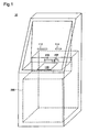
- FIG. 1 is an illustration depicting schematically the appearance of an ATM pertaining to Embodiment 1.
- FIG. 2 is an illustration depicting schematically the block configuration of the ATM pertaining to Embodiment 1.
- the ATM 10 includes a main controller 100, a card/statement processor 110, a touch panel 120, an administrator operation unit 130, a network interface 140, and a paper currency handling unit 200, which are interconnected through an internal bus 150.
- the main controller 100 controls the card/statement processor 110, the touch panel 120, the administrator operation unit 130, the network interface 140, and the paper currency handling unit 200.
- the card/statement processor 110 includes a passbook printer 112 and a reader/writer 114.
- the passbook printer 112 performs printing of transaction records or printing of passbook entries.
- the reader/writer 114 performs reading of data from or writing of data to a card.
- the touch panel 120 detects input from a customer.
- customer input refers to an instruction to make a deposit or a withdrawal, for example.
- the detected input is transmitted from the touch panel 120 to the main controller 100.
- the touch panel 120 has both an input detection function and a display function; it both detects customer input and displays messages from the ATM 10 to the customer.
- the administrator operation unit 130 detects operations performed by an administrator employee of the financial institution.
- the network interface 140 connects the ATM 10 to a network 20.
- the ATM 10 is connected to a host computer (not shown) via the network 20.
- the paper currency handling unit 200 performs discrimination of paper currency bills which have been deposited to the ATM 10, and transmits the discrimination results to the main controller 100 as well as sorting the paper currency bills and placing them in an internal repository. Upon receiving an instruction from the main controller 100, the paper currency handling unit 200 will retrieve and dispense paper currency bills from the internal repository.
- the paper currency handling unit 200 has both a paper currency accepting/dispensing unit 250 for accepting and dispensing paper currency, and a coin accepting/dispensing unit 252 for accepting and dispensing coins.
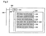
- FIG. 3 is an illustration showing the control block of the paper currency handling unit 200.
- FIG. 4 is an illustration depicting schematically the internal configuration of the paper currency handling unit 200.
- the control block of the paper currency handling unit 200 includes a CPU 210 and a memory 220 which are interconnected by an internal bus 240.
- the paper currency handling unit 200 is provided internally with a paper currency discriminating unit 260, a paper currency escrow repository 270, a counterfeit bill repository 272, a walk-away recovery repository 274, a paper currency recovery repository 276, recycling repositories 278a to 278e, paper currency transport devices 301 to 322, and switching gates 401 to 410.
- the paper currency discriminating unit 260 scans the currency bills and acquires currency data for the purpose of discerning the genuineness and denomination of the currency bills. In the present embodiment, determination of genuineness and denomination of currency bills is carried out through execution by the CPU 210, discussed later, of a paper currency discrimination program 224, discussed later, and processing of the currency data acquired by the paper currency discriminating unit 260.
- the paper currency escrow repository 270 provides temporary storage of genuine currency bills.
- the counterfeit bill repository 272 stores any counterfeit bills.
- the walk-away recovery repository 274 will store any currency bills that a customer has forgotten to retrieve when cash is dispensed or returned.
- the paper currency recovery repository 276 stores currency bills which are genuine but damaged to the point of being unsuitable for recirculation.
- the recycling repositories 278a through 278e store currency bills which are genuine and suitable for recirculation.
- five recycling repositories 278a through 278e are provided in association with different denominations. It would be acceptable to provide two or more of recycling repositories 278a through 278e for a single denomination. Where recycling repositories 278a through 278e are not distinguished in this way, they will be denoted as recycling repositories 278.
- the paper currency recovery repository 276 and the recycling repositories 278 are located within a safe 280.
- the paper currency transport devices 301 to 322 are transport devices for transporting currency bills.
- the paper currency transport devices 301 to 322 use belts or rollers for example to transport the currency bills.
- the switching gates 401 to 410 are gates for switching the transport direction of currency bills.
- the switching gates 401 to 410 have transport devices in three or four directions, and will shunt a paper currency bill transported from one of these directions into any of the remaining two or three directions.
- the placement of the paper currency transport devices 301 to 322 and the switching gates 401 to 410 will be described with reference to FIG. 4 .
- the paper currency transport device 301, the switching gate 401, the paper currency transport device 302, the switching gate 402, and the paper currency transport device 303 are situated between the paper currency accepting/dispensing unit 250 and the paper currency discriminating unit 260.
- the paper currency transport device 304, the switching gate 403, and the paper currency transport device 305 are situated between the paper currency discriminating unit 260 and the paper currency escrow repository 270.
- the paper currency transport device 306, the switching gate 404, and the paper currency transport device 307 are situated between the switching gate 403 and the paper currency accepting/dispensing unit 250.
- the paper currency transport device 311 is situated between the switching gate 402 and the switching gate 404.
- the paper currency transport device 308, the switching gate 405, and the paper currency transport device 309 are situated between the switching gate 403 and the counterfeit bill repository 272.
- the paper currency transport device 310 is situated between the switching gate 405 and the walk-away recovery repository 274.
- the paper currency transport device 312, the switching gate 406, the paper currency transport device 313, the switching gate 407, the paper currency transport device 314, the switching gate 408, the paper currency transport device 315, the switching gate 409, the paper currency transport device 316, the switching gate 410, and the paper currency transport device 317 are situated between the switching gate 401 and the paper currency recovery repository 276.
- the paper currency transport devices 318 through 322 are situated respectively between the switching gates 406 through 410 and the recycling repositories 278a-e.
- the CPU 210 controls the operation of the paper currency accepting/dispensing unit 250, the paper currency discriminating unit 260, the paper currency escrow repository 270, the counterfeit bill repository 272, the walk-away recovery repository 274, the paper currency recovery repository 276, the recycling repositories 278, the paper currency transport devices 301 to 322, and the switching gates 401 to 410.
- the memory 220 has stored in memory therein a paper currency feed control program 222, the paper currency discrimination program 224, a transport speed acquisition program 226, a paper currency arrival time prediction program 228, a paper currency transport control program 230, and a switching gate control program 232.
- the paper currency feed control program 222 will perform control of feed of the currency bills by halting the feed of currency bills from the paper currency accepting/dispensing unit 250, the paper currency escrow repository 270, the recycling repositories 278, and so on.
- the paper currency discrimination program 224 uses the currency bill data acquired from currency bills by the paper currency discriminating unit 260 to determine the genuineness and denomination of the currency bills.
- the transport speed acquisition program 226 uses the point in time that a currency bill arrived at a sensor (discussed later), which has been recorded in the memory 220, and the distance between sensors, which is stored in memory 220, to determine the transport speed of the currency bill.
- the paper currency arrival time prediction program 228 uses the time of arrival at a given sensor to predict the time of arrival at the next sensor. In general, when calculating the transport speed of a currency bill it will be necessary for the bill to pass sensors at two locations. However, if a currency bill fails to reach the next sensor within a prescribed time interval from the time at which it passed the first sensor, it can be detected that the currency bill transport speed has been slowed, even if the actual transport speed of the bill is not known.
- the paper currency transport control program 230 controls operations of the paper currency transport device 301 through 322. For example, if slow transport speed is detected, it will control a prescribed paper currency transport device so as to reverse its direction of rotation.
- the switching gate control program 232 controls the direction of shunting of transported paper currency in the switching gates 401 through 410.
- FIG. 5 is a flowchart depicting operation of an ATM 10 when making a deposit.
- FIG. 6 is a flowchart depicting operation of an ATM 10 when making a withdrawal.
- typical operations during an ATM 10 deposit and withdrawal will be described; the paper currency transport control which is a particular feature of the present embodiment will be discussed later.
- the main controller 100 When an instruction to initiate a deposit is made on the touch panel 120 by the user, the main controller 100 will open the door of the paper currency accepting/dispensing unit 250 and wait for currency bills to be placed in the paper currency accepting/dispensing unit 250 (Step S100).
- the CPU 210 Upon receiving an instruction from the main controller 100, the CPU 210 will switch the switching gates 401, 402 so that the currency bills are transported from the paper currency accepting/dispensing unit 250 to the paper currency discriminating unit 260, and will then drive the paper currency transport devices 301 to 303 to feed the currency bills to the paper currency discriminating unit 260, acquire paper currency data from the paper currency discriminating unit 260, and determine the genuineness and denomination of the currency bills (Step S110).
- the CPU 210 will record the denomination in the memory 220, switch the switching gate 403 so that the bill is transported to the paper currency escrow repository 270, and drive the paper currency transport devices 304, 305 to transport the bill to the paper currency escrow repository 270.
- the CPU 210 will switch the switching gates 403, 405 so that the bill is transported to the counterfeit bill repository 272, and drive the paper currency transport devices 304, 308, and 309 to transport the bill to counterfeit bill repository 272 (Step S120).
- the main controller 100 will then display on the touch panel 120 the total amount of the denominations of the deposited paper currency (Step S130), and will wait for an instruction from the user.
- the main controller 100 will instruct the paper currency handling unit 200 to transport the currency bills to the paper currency recovery repository 276 and the recycling repositories 278 (Step S150).
- the CPU 210 upon receiving an instruction from the main controller 100, the CPU 210 will switch the switching gate 403 so that the currency bills are transported to the paper currency discriminating unit 260, and drive the paper currency transport devices 305, 304 to transport the bills to the paper currency discriminating unit 260.
- the CPU 210 will then acquire the currency bill data from the paper currency discriminating unit 260 and re-check the paper currency denominations. On the basis of the paper currency denominations the CPU 210 will determine whether to transport the bills to the paper currency recovery repository 276 or the recycling repositories 278a-e, and perform the appropriate switching of the switching gates 402, 401, and 406 through 410. The CPU 210 will then drive the paper currency transport devices 303, 302, and 312 through 322 to transport the bills to their determined transport destinations.
- Step S140 the main controller 100 will instruct the paper currency handling unit 200 to transport the paper currency to the paper currency accepting/dispensing unit 250 (Step S160) and return the bills to the user.
- the CPU 210 upon receiving an instruction from the main controller 100, the CPU 210 will switch the switching gates 403, 404 so that the currency bills are transported to the paper currency accepting/dispensing unit 250, and then drive the paper currency transport devices 305 through 307 to transport the bills to the paper currency accepting/dispensing unit 250.
- Step S200 When a withdrawal instruction is made on the touch panel 120 by the user (Step S200), the main controller 100 will detect this, and instruct the paper currency handling unit 200 to transport paper currency to the paper currency accepting/dispensing unit 250.
- the CPU 210 Upon receiving an instruction from the main controller 100, the CPU 210 will determine from which of the recycling repositories 278a-e to withdraw currency bills, and will switch the switching gates 406 through 410, 401, and 402 so that the bills are transported from the prescribed recycling repositories 278a-e to the paper currency discriminating portion unit. The CPU 210 will then drive the paper currency transport devices 318 to 322, 312 to 316, 302, and 303 to convey the bills to the paper currency discriminating unit 260, where their denominations will be determined (Step S210).
- Step S220 the CPU 210 will switch the switching gates 403, 404 so that the bills are transported to the paper currency accepting/dispensing unit 250, drive the paper currency transport devices 304, 306, 307, and transport the bills to the paper currency accepting/dispensing unit 250 (Step S230). Once all of the bills for withdrawal have been transported to the paper currency accepting/dispensing unit250, the CPU 210 will dispense the bills to the user.
- Step S220 the CPU 210 will switch the switching gate 403 so that the bill is transported to the paper currency escrow repository 270, and drive the paper currency transport devices 304, 305 to transport the bill to the paper currency escrow repository 270.
- the main controller 100 will now transport bills that were transported to the paper currency escrow repository 270 to the paper currency recovery repository 276 and the recycling repositories 278 (the recycling repositories 278a-e) (Step S240). This operation is identical to the operation of transporting bills from the paper currency escrow repository 270 to the paper currency recovery repository 276 and the recycling repositories 278 during a deposit, and will not be described.
- FIG. 7 is an illustration showing in detail the path leading from the paper currency accepting/dispensing unit 250 to the paper currency discriminating unit 260.
- a paper currency transport path 350 is formed by the paper currency transport devices 301 to 303 between the paper currency accepting/dispensing unit 250 and the paper currency discriminating unit 260; and sensors 501 to 503 are positioned along the paper currency transport path 350.
- the sensors 501 to 503 are respectively composed of light-emitting elements 501a to 503a, and photoreceptor elements 501b to 503b.
- the sensors 501 to 503 are transmission type sensors in which the light-emitting elements 501a to 503a and the photoreceptor elements 501b to 503b are disposed to either side of the paper currency transport path 350; however, it would also be acceptable to use reflection type sensors in which the light-emitting elements 501a to 503a and the photoreceptor elements 501b to 503b are disposed to the same side of the paper currency transport path 350. Since the signals from the photoreceptor elements will change as currency bills block the light between the light-emitting elements and the photoreceptor elements, the CPU 210 will detect passage of bills by reading the values of the signals from the photoreceptor elements. In the present embodiment, three sensors have been provided between the paper currency accepting/dispensing unit 250 to the paper currency discriminating unit 260, but the number of sensors is not limited to three, and may be a different number.
- FIG. 8 is a flowchart depicting transport control of paper currency according to an illustrative example not embodying the invention.
- currency bills When currency bills are deposited, they will be fed one at a time to the paper currency transport path 350 from the paper currency accepting/dispensing unit 250.
- the bills will then be transported by the paper currency transport device 301, and as they pass the location of the sensor 501 the value of the signal from the sensor 501 will change, whereby the CPU 210 will detect arrival of the bills at the sensor 501 (Step S300).
- the CPU 210 will record the time t1 of arrival of a bill at the sensor 501 in the memory 220 (Step S305).
- the bill will then be transported forward by the paper currency transport devices 301, 302.
- the signal from the sensor 502 will change, whereby the CPU 210 will detect arrival of bills at the sensor 502 (Step S310).
- the CPU 210 will record the time t2 of arrival of the bill at the sensor 502 in the memory 220 (Step S315).
- the CPU 210 Since the distance between the sensor 501 and the sensor 502 has been pre-stored in the memory 220, the CPU 210 will be able to calculate the currency bill transport speed from the distance between the sensor 501 and the sensor 502, and the difference between the time t1 of arrival of a bill at the sensor 501 and the time t2 of arrival of the bill at the sensor 502 (Step S320).
- Step S325 the CPU 210 will halt feed of the bill from the paper currency accepting/dispensing unit 250 and rotate the paper currency transport device 301 backward in order to reverse the subsequently dispensed bill (hereinafter termed the "following bill”; in association therewith, the corresponding bill transported at slow speed at this time is termed the "leading bill.”) back into the paper currency accepting/dispensing unit 250 (Step S330).
- the currency bill will then be transported forward by the paper currency transport devices 302, 303.
- the signal from the sensor 503 will change, and thus the CPU 210 can detect that the bill has reached the sensor 503 (Step S335).
- the CPU 210 will record the time t3 of arrival of the bill at the sensor 503 in the memory 220 (Step S340).
- the CPU 210 Since the distance between the sensor 502 and the sensor 503 has been pre-stored in the memory 220, the CPU 210 will be able to calculate the currency bill transport speed from the distance between the sensor 502 and the sensor 503, and the difference between the time t2 of arrival of the bill at the sensor 502 and the time t3 of arrival of the bill at the sensor 503 (Step S345). In the event that the calculated transport speed is smaller than a prescribed value (Step S350: Yes), the CPU 210 will halt feed of the bill from the paper currency accepting/dispensing unit 250 and rotate the paper currency transport devices 301, 302 in backward in order to reverse the following bill back into the paper currency accepting/dispensing unit 250 (Step S330).
- the CPU 210 will calculate the transport speed of currency bills from the distance between two adjacent sensors and the difference in arrival times, and in the event it detects a bill moving at transport speed slower than a prescribed transport speed, it will rotate in reverse the paper currency transport devices situated between the bill traveling at slow speed and the paper currency accepting/dispensing unit 250.
- the CPU 210 will for example issue an alert to financial institution service personnel to request repair of the ATM 10. If jamming occurs due to overlapping bills, depending on the condition of the jam, recovery may be difficult; according to the illustrative example, however, leading bills will be conveyed forward while following bills will be conveyed backward, thus avoiding jams caused by overlap. Accordingly, it will be easier for service personnel to repair the ATM 10.
- Verification of transport speed will be carried out for all paper currency bills which are fed from the paper currency accepting/dispensing unit 250. For example, if the CPU 210 has detected that the third bill (leading bill) which was fed is being transported at slow speed, it will perform control such that the paper currency transport device reached by the fourth bill (following bill), as well as the paper currency transport device lying towards the paper currency accepting/dispensing unit 250 side of this device, now rotate in reverse.
- the process of transporting bills from the recycling repositories 278 to the paper currency accepting/dispensing unit 250 during withdrawal is also analogous to the above. Specifically, if the CPU 210 detects slow transport speed from a sensor signal, it will halt the feed of the bills, and perform control to rotate in reverse the paper currency transport device which is situated towards the feed side from the bill which was detected to be transported at slow speed.
- the CPU 210 detects a bill transported at slow speed, it will perform control to rotate in reverse the paper currency transport device which is situated towards the feed side from the detected bill, thereby preventing the leading bill and the following bill from overlapping and causing jamming.
- FIG. 9 is a flowchart depicting transport control of paper currency in the preferred embodiment.
- the configuration is the same as the configuration described above, so the configuration will not be discussed.
- the CPU 210 will then predict the time at which the bill will reach the sensor 502 (Step S410) and record this value to the memory 220 (Step S415).
- the distance between the sensor 501 and the sensor 502 is a known value, and since the transport speed by the paper currency transport devices 301, 302 is also known, if the time t1 of arrival of a bill at the sensor 501 is known it will be a simple matter to predict the time of arrival t2a at the sensor 502.
- the CPU 210 will then wait for the bill to reach the sensor 502 (Step S420). If before the bill reaches the sensor 502 (Step S420: No) the elapsed time has passed t2a (Step S425: Yes), the CPU 210 will detect that delayed transport of the bill has occurred (Step S430). The CPU 210 will then halt the feed of bills from the paper currency accepting/dispensing unit 250 and reverse the following bills back into the paper currency accepting/dispensing unit 250 (Step S435). Specifically, the CPU 210 will rotate the paper currency transport device 301 in reverse.
- Step S420 If the CPU 210 detects that the bill has reached the sensor 502 (Step S420: Yes), it will record the time t2 of arrival of the bill at the sensor 502 in the memory 220 (Step S440). The CPU 201 will then predict the time at which the bill will reach the sensor 503 (Step S445), and record this value to the memory 220 (Step S450).
- the distance between the sensor 502 and the sensor 503 is a known value, and since the transport speed by the paper currency transport devices 302, 303 is also known, if the time t2 of arrival of a bill at the sensor 502 is known it will be a simple matter to predict the time of arrival t3a at the sensor 503.
- the CPU 210 will then wait for the bill to reach the sensor 503 (Step S455). If before the bill reaches the sensor 503 (Step S455: No) the elapsed time has passed t3a (Step S460: Yes), the CPU 210 will detect that delayed transport of the bill has occurred (Step S430). The CPU 210 will then halt the feed of bills from the paper currency accepting/dispensing unit 250 and reverse the following bills back into the paper currency accepting/dispensing unit 250 (Step S435). Specifically, the CPU 210 will rotate the paper currency transport devices 301, 302 in reverse.
- Step S455 If the CPU 210 detects that the bill has reached the sensor 503 (Step S455: Yes), it will record the time t3 of arrival of the bill at the sensor 503 in the memory 220 (Step S465). The time t3 will be used to predict the time t4a of arrival of the bill at the next sensor. The subsequent process is a repeat of the above and will not be described.
- the CPU 210 can detect delayed transport of currency bills even before a bill reaches the next sensor. Accordingly, it will be possible to prevent jamming caused by overlapping paper currency bills in the event that, for example, the transport speed of a bill slows markedly for some reason during transport, or where it ceases to move at all.
- the CPU 210 will carry out control in such a way as to reverse the rotation of the paper currency transport devices so that the following bill will be conveyed in the reverse direction.
- the CPU 210 may wait until a fed bill has reached the initial sensor 501 before feeding the next bill. This can prevent jamming caused by overlap of bills before reaching the initial sensor 501.
- the CPU 210 may also feed and control the transport of bills in such a way that two or more bills will never be present between neighboring sensors. This can prevent jamming caused by overlapping bills.
- sensors are positioned midway along the paper currency transport devices, but the sensors could instead be positioned between two neighboring paper currency transport devices. Since currency bill transport speed can be changed in before or after sensors, jamming caused by overlapping bills can be prevented.
- the illustrative example and the preferred embodiment described three sensors positioned between the paper currency accepting/dispensing unit 250 and the paper currency discriminating unit 260; however, it would be possible for example to position multiple sensors on other paper currency transport paths, such as that between the paper currency discriminating unit 260 to the paper currency escrow repository 270, that between the paper currency escrow repository 270 and the paper currency accepting/dispensing unit 250, or that between the paper currency escrow repository 270 and the paper currency recovery repository 276 or the recycling repositories 278.
- a leading bill transported at slow speed will continue to be transported forward, but it would be possible for the leading bill to be returned to the feed source as well.
- return may take place at a slower transport speed than normal.
Landscapes
- Physics & Mathematics (AREA)
- General Physics & Mathematics (AREA)
- Business, Economics & Management (AREA)
- Accounting & Taxation (AREA)
- Finance (AREA)
- Controlling Sheets Or Webs (AREA)
- Financial Or Insurance-Related Operations Such As Payment And Settlement (AREA)
- Sheets, Magazines, And Separation Thereof (AREA)
Claims (4)
- Papierblatt-Aufbewahrungsvorrichtung mit
einer Papierblatt-Transporteinheit, die einen Transportpfad (350) für Papierblätter aufweist,
einer Papierblatt-Zuführeinheit (301-303) zum Zuführen von Papierblättern auf den Transportpfad (350),
mehreren Sensoren (501-503), die auf dem Transportpfad (350) angeordnet sind, um den Durchgang eines vorderen Papierblatts zu erfassen, wobei die mehreren Sensoren (501-503) einen ersten und einen zweiten Sensor umfassen, die nebeneinander angeordnet sind, und
einer Steuereinheit (210) zum Steuern der Papierblatt-Transporteinheit und der Papierblatt-Zuführeinheit (301-303),
gekennzeichnet durch eine Ankunftszeit-Vorhersageeinheit (228), um aus einem Zeitpunkt (t1; t2), zu dem das vordere Papierblatt den ersten Sensor (501; 502) passiert, eine Ankunftszeit (t2a; t3a) des vorderen Papierblatts an den zweiten Sensor (502; 503) vorherzusagen,
wobei für den Fall, dass das vordere Papierblatt nicht innerhalb einer vorbestimmten Zeitspanne beginnend von der vorhergesagten Ankunftszeit (t2a; t3a) an dem zweiten Sensor (502; 503) ankommt, die Steuereinheit (210) dazu ausgelegt ist, die Papierblattzuführeinheit (301-303) dazu zu veranlassen, die Zuführung der nachfolgenden Papierblätter anzuhalten und einen Abschnitt der Papierblatt-Transporteinheit, der näher an der Papierblatt-Zuführeinheit (301-303) angeordnet ist als der erste Sensor (501; 502), rückwärts zu betreiben, während das vordere Papierblatt weiterhin vorwärts transportiert wird. - Papierblatt-Aufbewahrungsvorrichtung nach Anspruch 1, ferner mit
einer Transportgeschwindigkeits-Ermittlungseinheit (226) zum Ermitteln der Bewegungsgeschwindigkeit eines Papierblatts basierend auf einem Abstand zwischen dem ersten und dem zweiten Sensor und einem Unterschied zwischen dem Zeitpunkt (t1; t2), zu dem das vordere Papierblatt den ersten Sensor (501; 502) passiert, und einem anderen Zeitpunkt (t2; t3), zu dem das vordere Papierblatt den zweiten Sensor (502; 503) passiert. - Verfahren zum Steuern einer Papierblatt-Aufbewahrungsvorrichtung, in dem
Papierblätter von einer Papierblatt-Zuführeinheit (301-303) zugeführt werden,
eine Papierblatt-Transporteinheit zum Transport der Papierblätter verwendet wird,
mehrere Sensoren (501-503) verwendet werden, die erste und zweite Sensoren umfassen, die nebeneinander angeordnet sind, um den Durchgang eines vorderen Papierblatts zu erfassen,
aus einem Zeitpunkt (t1; t2), zu dem das vordere Papierblatt den ersten Sensor (501; 502) passiert, eine Ankunftszeit (t2a; t3a) des vorderen Papierblatts an dem zweiten Sensor (502; 503) vorhergesagt wird, und
für den Fall, dass das vordere Papierblatt nicht innerhalb einer vorbestimmten Zeitspanne beginnend von der vorhergesagten Ankunftszeit (t2a; t3a) an dem zweiten Sensor (502; 503) ankommt, die Papierblatt-Zuführeinheit (301-303) dazu veranlasst wird, die Zuführung nachfolgender Papierblätter anzuhalten und einen Abschnitt der Papierblatt-Transporteinheit, der näher an der Papierblatt-Zuführeinheit (301-303) angeordnet ist als der erste Sensor (501; 502), rückwärts zu betreiben, während das vordere Papierblatt weiterhin vorwärts transportiert wird. - Auf einem Computer-lesbaren Medium gespeichertes Computerprogramm zum Steuern einer Papierblatt-Aufbewahrungsvorrichtung, um bei Ausführung durch einen Computer das Verfahren gemäß Anspruch 3 durchzuführen.
Applications Claiming Priority (1)
| Application Number | Priority Date | Filing Date | Title |
|---|---|---|---|
| JP2007236327A JP2009067513A (ja) | 2007-09-12 | 2007-09-12 | 紙葉類集積装置並びに紙葉類集積装置の制御方法及び制御プログラム |
Publications (3)
| Publication Number | Publication Date |
|---|---|
| EP2036843A2 EP2036843A2 (de) | 2009-03-18 |
| EP2036843A3 EP2036843A3 (de) | 2011-08-31 |
| EP2036843B1 true EP2036843B1 (de) | 2014-06-25 |
Family
ID=40129693
Family Applications (1)
| Application Number | Title | Priority Date | Filing Date |
|---|---|---|---|
| EP08010926.7A Not-in-force EP2036843B1 (de) | 2007-09-12 | 2008-06-16 | Papierbogenaufbewahrungsvorrichtung und Steuerverfahren und Steuerprogramm für eine Papierbogenaufbewahrungsvorrichtung |
Country Status (6)
| Country | Link |
|---|---|
| US (1) | US20090066017A1 (de) |
| EP (1) | EP2036843B1 (de) |
| JP (1) | JP2009067513A (de) |
| KR (1) | KR101025246B1 (de) |
| CN (1) | CN101388122B (de) |
| TW (2) | TWI434232B (de) |
Families Citing this family (14)
| Publication number | Priority date | Publication date | Assignee | Title |
|---|---|---|---|---|
| DE102008061530A1 (de) * | 2008-12-10 | 2010-06-17 | Wincor Nixdorf International Gmbh | Verfahren zum Befüllen mindestens eines dünnwandigen Transportbehälters mit mindestens einem Wertgegenstand und Vorrichtung zur Aufbewahrung mindestens eines Wertgegenstandes |
| BRPI1103612A2 (pt) * | 2011-07-20 | 2013-02-26 | Tecnologia Bancaria Sa | dispositivo e mÉtodo para multiaplicaÇço atm |
| EP2771188B1 (de) * | 2011-10-24 | 2017-05-31 | Bobst Mex Sa | Verfahren und anordnung zum einrichten einer druckmaschine |
| US8366105B1 (en) * | 2011-12-27 | 2013-02-05 | Xerox Corporation | Motion quality by automatic velocity match between upstream and downstream transports |
| TWM448108U (zh) * | 2012-09-12 | 2013-03-01 | Celestica Int Inc | 電路板高度調整及減震結構及設有該電路板高度調整及減震結構之伺服器 |
| CN104058279B (zh) * | 2013-03-18 | 2016-10-05 | 株式会社东芝 | 纸张类处理装置 |
| JP2014206438A (ja) * | 2013-04-12 | 2014-10-30 | 株式会社東芝 | 蛍光残光検出装置、及び紙葉類処理装置 |
| CN104021613A (zh) * | 2014-04-30 | 2014-09-03 | 昆山古鳌电子机械有限公司 | 一种能够判别纸张类冠字号的纸张类集积装置 |
| WO2017187529A1 (ja) * | 2016-04-26 | 2017-11-02 | 富士通フロンテック株式会社 | 紙葉類取扱装置及び紙葉類取扱方法 |
| CN106157466B (zh) * | 2016-07-25 | 2018-10-19 | 深圳怡化电脑股份有限公司 | 纸币残留检测方法及装置 |
| TWI602157B (zh) * | 2016-08-08 | 2017-10-11 | 鴻發國際科技股份有限公司 | 輸送路徑切換模組及紙頁處理設備 |
| CN108961528B (zh) * | 2017-05-27 | 2021-04-13 | 山东新北洋信息技术股份有限公司 | 硬币分离装置及分离方法 |
| TWI622961B (zh) | 2017-06-27 | 2018-05-01 | 鴻發國際科技股份有限公司 | 輸送路徑切換模組、紙頁處理模組及紙頁處理設備 |
| CN110288763B (zh) * | 2018-03-13 | 2021-05-07 | 山东新北洋信息技术股份有限公司 | 一种纸币排错方法及现金循环处理设备 |
Citations (2)
| Publication number | Priority date | Publication date | Assignee | Title |
|---|---|---|---|---|
| US5667215A (en) * | 1994-09-16 | 1997-09-16 | Kabushiki Kaisha Toshiba | Paper conveying device |
| JP2000255842A (ja) * | 1999-03-09 | 2000-09-19 | Ricoh Co Ltd | 画像形成装置の給紙制御方法及び同給紙制御装置 |
Family Cites Families (16)
| Publication number | Priority date | Publication date | Assignee | Title |
|---|---|---|---|---|
| JPS63306138A (ja) * | 1987-06-08 | 1988-12-14 | Nec Corp | 連鎖補正機構 |
| US5112038A (en) * | 1991-07-01 | 1992-05-12 | Eastman Kodak Company | Feedback control for receiver member in-track registration in an electrostatographic reproduction apparatus or the like |
| JP3248972B2 (ja) * | 1993-04-07 | 2002-01-21 | 沖電気工業株式会社 | 紙幣入出金装置 |
| JP2995538B2 (ja) * | 1995-06-22 | 1999-12-27 | 沖電気工業株式会社 | 紙葉類取扱装置 |
| JPH09114156A (ja) * | 1995-10-19 | 1997-05-02 | Ricoh Co Ltd | 画像形成装置 |
| JP3540526B2 (ja) * | 1996-11-27 | 2004-07-07 | 株式会社東芝 | 紙葉類処理装置、紙葉類裁断装置、および紙葉類処理方法 |
| US6644660B2 (en) * | 2001-10-26 | 2003-11-11 | Pitney Bowes Inc. | Dynamic pitch correction for an output inserter subsystem |
| US6554275B1 (en) * | 2001-12-04 | 2003-04-29 | Unisys Corporation | Method and system for document overlap/gap error detection and correction |
| US7308853B2 (en) * | 2003-03-11 | 2007-12-18 | Tohoku Ricoh Co., Ltd. | Bulk paper feeding device with intermediate conveyor for image forming device |
| JP4366122B2 (ja) * | 2003-06-24 | 2009-11-18 | 日立オムロンターミナルソリューションズ株式会社 | 紙葉類搬送装置 |
| JP4184904B2 (ja) * | 2003-09-03 | 2008-11-19 | 株式会社東芝 | 紙葉類分離搬送装置 |
| JP4634073B2 (ja) * | 2004-06-29 | 2011-02-16 | マミヤ・オーピー株式会社 | 紙葉類識別装置及び識別方法 |
| JP4469671B2 (ja) * | 2004-07-09 | 2010-05-26 | 株式会社東芝 | 紙葉類取り出し装置 |
| JP4643296B2 (ja) * | 2005-02-08 | 2011-03-02 | 日立オムロンターミナルソリューションズ株式会社 | 紙幣鑑別装置 |
| GB2429767B (en) * | 2005-09-06 | 2010-05-12 | Int Currency Tech | Banknote output control device that prevents supply of stacked banknotes |
| JP2007153560A (ja) * | 2005-12-06 | 2007-06-21 | Fuji Xerox Co Ltd | 給紙装置および画像形成装置 |
-
2007
- 2007-09-12 JP JP2007236327A patent/JP2009067513A/ja active Pending
-
2008
- 2008-05-20 TW TW101105094A patent/TWI434232B/zh not_active IP Right Cessation
- 2008-05-20 TW TW097118506A patent/TW200912807A/zh not_active IP Right Cessation
- 2008-06-16 EP EP08010926.7A patent/EP2036843B1/de not_active Not-in-force
- 2008-06-19 US US12/142,427 patent/US20090066017A1/en not_active Abandoned
- 2008-06-20 KR KR1020080058315A patent/KR101025246B1/ko not_active Expired - Fee Related
- 2008-06-20 CN CN2008101288307A patent/CN101388122B/zh not_active Expired - Fee Related
Patent Citations (2)
| Publication number | Priority date | Publication date | Assignee | Title |
|---|---|---|---|---|
| US5667215A (en) * | 1994-09-16 | 1997-09-16 | Kabushiki Kaisha Toshiba | Paper conveying device |
| JP2000255842A (ja) * | 1999-03-09 | 2000-09-19 | Ricoh Co Ltd | 画像形成装置の給紙制御方法及び同給紙制御装置 |
Also Published As
| Publication number | Publication date |
|---|---|
| CN101388122A (zh) | 2009-03-18 |
| KR101025246B1 (ko) | 2011-03-29 |
| TWI434232B (zh) | 2014-04-11 |
| TW201246132A (en) | 2012-11-16 |
| EP2036843A2 (de) | 2009-03-18 |
| EP2036843A3 (de) | 2011-08-31 |
| TWI365426B (de) | 2012-06-01 |
| JP2009067513A (ja) | 2009-04-02 |
| US20090066017A1 (en) | 2009-03-12 |
| CN101388122B (zh) | 2013-03-20 |
| TW200912807A (en) | 2009-03-16 |
| KR20090027563A (ko) | 2009-03-17 |
Similar Documents
| Publication | Publication Date | Title |
|---|---|---|
| EP2036843B1 (de) | Papierbogenaufbewahrungsvorrichtung und Steuerverfahren und Steuerprogramm für eine Papierbogenaufbewahrungsvorrichtung | |
| US7357303B2 (en) | Bill handling apparatus | |
| US7950655B2 (en) | Apparatus and method for controlling various kinds of paper media with skew sensing | |
| EP2503519B1 (de) | Geldhandhabungsvorrichtung | |
| CN101430805B (zh) | 纸张类处理装置 | |
| JP5547702B2 (ja) | 紙幣表裏整列装置および紙幣表裏整列方法 | |
| JP2995538B2 (ja) | 紙葉類取扱装置 | |
| WO2015019696A1 (ja) | 紙葉類取扱装置 | |
| JPH11224362A (ja) | 紙幣取扱装置 | |
| JP3212673B2 (ja) | 紙幣ジャムの復旧方法及び復旧装置 | |
| AU2023266292A1 (en) | Banknote deposit-withdrawal system and architecture | |
| JPH01256435A (ja) | 現金自動取扱装置 | |
| KR20100080189A (ko) | 금융자동화기기의 일시저장부에서 분리되는 지폐의 정렬 방법 | |
| JP3626289B2 (ja) | 貨幣処理装置 | |
| JP2019109644A (ja) | 自動機監視装置 | |
| JP7218223B2 (ja) | 自動取引装置、判定方法およびプログラム | |
| JP2006184991A (ja) | 現金自動取引装置 | |
| KR101203762B1 (ko) | 지폐취급장치 및 지폐취급방법 | |
| KR102109030B1 (ko) | 동일 반송계를 구비한 현금 입출금장치 | |
| JPH11265472A (ja) | 現金自動入出金装置 | |
| JP2008305309A (ja) | 搬送装置および貨幣処理機 | |
| JP2006315801A (ja) | 紙葉類搬送装置 | |
| KR20240083519A (ko) | 금융자동화기기의 지폐 반송 게이트 운용 방법 | |
| KR20090096819A (ko) | 매체입금장치 및 그 제어방법 | |
| JP2001048416A (ja) | 貨幣処理装置 |
Legal Events
| Date | Code | Title | Description |
|---|---|---|---|
| PUAI | Public reference made under article 153(3) epc to a published international application that has entered the european phase |
Free format text: ORIGINAL CODE: 0009012 |
|
| AK | Designated contracting states |
Kind code of ref document: A2 Designated state(s): AT BE BG CH CY CZ DE DK EE ES FI FR GB GR HR HU IE IS IT LI LT LU LV MC MT NL NO PL PT RO SE SI SK TR |
|
| AX | Request for extension of the european patent |
Extension state: AL BA MK RS |
|
| 17P | Request for examination filed |
Effective date: 20100331 |
|
| PUAL | Search report despatched |
Free format text: ORIGINAL CODE: 0009013 |
|
| AK | Designated contracting states |
Kind code of ref document: A3 Designated state(s): AT BE BG CH CY CZ DE DK EE ES FI FR GB GR HR HU IE IS IT LI LT LU LV MC MT NL NO PL PT RO SE SI SK TR |
|
| AX | Request for extension of the european patent |
Extension state: AL BA MK RS |
|
| RIC1 | Information provided on ipc code assigned before grant |
Ipc: B65H 7/18 20060101AFI20110725BHEP |
|
| AKX | Designation fees paid |
Designated state(s): AT BE BG CH CY CZ DE DK EE ES FI FR GB GR HR HU IE IS IT LI LT LU LV MC MT NL NO PL PT RO SE SI SK TR |
|
| 17Q | First examination report despatched |
Effective date: 20120613 |
|
| GRAP | Despatch of communication of intention to grant a patent |
Free format text: ORIGINAL CODE: EPIDOSNIGR1 |
|
| INTG | Intention to grant announced |
Effective date: 20140103 |
|
| GRAS | Grant fee paid |
Free format text: ORIGINAL CODE: EPIDOSNIGR3 |
|
| GRAA | (expected) grant |
Free format text: ORIGINAL CODE: 0009210 |
|
| AK | Designated contracting states |
Kind code of ref document: B1 Designated state(s): AT BE BG CH CY CZ DE DK EE ES FI FR GB GR HR HU IE IS IT LI LT LU LV MC MT NL NO PL PT RO SE SI SK TR |
|
| REG | Reference to a national code |
Ref country code: GB Ref legal event code: FG4D |
|
| REG | Reference to a national code |
Ref country code: CH Ref legal event code: EP |
|
| REG | Reference to a national code |
Ref country code: AT Ref legal event code: REF Ref document number: 674527 Country of ref document: AT Kind code of ref document: T Effective date: 20140715 |
|
| REG | Reference to a national code |
Ref country code: IE Ref legal event code: FG4D |
|
| REG | Reference to a national code |
Ref country code: DE Ref legal event code: R096 Ref document number: 602008032934 Country of ref document: DE Effective date: 20140814 |
|
| PG25 | Lapsed in a contracting state [announced via postgrant information from national office to epo] |
Ref country code: NO Free format text: LAPSE BECAUSE OF FAILURE TO SUBMIT A TRANSLATION OF THE DESCRIPTION OR TO PAY THE FEE WITHIN THE PRESCRIBED TIME-LIMIT Effective date: 20140925 Ref country code: FI Free format text: LAPSE BECAUSE OF FAILURE TO SUBMIT A TRANSLATION OF THE DESCRIPTION OR TO PAY THE FEE WITHIN THE PRESCRIBED TIME-LIMIT Effective date: 20140625 Ref country code: GR Free format text: LAPSE BECAUSE OF FAILURE TO SUBMIT A TRANSLATION OF THE DESCRIPTION OR TO PAY THE FEE WITHIN THE PRESCRIBED TIME-LIMIT Effective date: 20140926 Ref country code: CY Free format text: LAPSE BECAUSE OF FAILURE TO SUBMIT A TRANSLATION OF THE DESCRIPTION OR TO PAY THE FEE WITHIN THE PRESCRIBED TIME-LIMIT Effective date: 20140625 Ref country code: LT Free format text: LAPSE BECAUSE OF FAILURE TO SUBMIT A TRANSLATION OF THE DESCRIPTION OR TO PAY THE FEE WITHIN THE PRESCRIBED TIME-LIMIT Effective date: 20140625 |
|
| REG | Reference to a national code |
Ref country code: AT Ref legal event code: MK05 Ref document number: 674527 Country of ref document: AT Kind code of ref document: T Effective date: 20140625 |
|
| REG | Reference to a national code |
Ref country code: NL Ref legal event code: VDEP Effective date: 20140625 |
|
| REG | Reference to a national code |
Ref country code: LT Ref legal event code: MG4D |
|
| PG25 | Lapsed in a contracting state [announced via postgrant information from national office to epo] |
Ref country code: HR Free format text: LAPSE BECAUSE OF FAILURE TO SUBMIT A TRANSLATION OF THE DESCRIPTION OR TO PAY THE FEE WITHIN THE PRESCRIBED TIME-LIMIT Effective date: 20140625 Ref country code: LV Free format text: LAPSE BECAUSE OF FAILURE TO SUBMIT A TRANSLATION OF THE DESCRIPTION OR TO PAY THE FEE WITHIN THE PRESCRIBED TIME-LIMIT Effective date: 20140625 Ref country code: SE Free format text: LAPSE BECAUSE OF FAILURE TO SUBMIT A TRANSLATION OF THE DESCRIPTION OR TO PAY THE FEE WITHIN THE PRESCRIBED TIME-LIMIT Effective date: 20140625 |
|
| PG25 | Lapsed in a contracting state [announced via postgrant information from national office to epo] |
Ref country code: RO Free format text: LAPSE BECAUSE OF FAILURE TO SUBMIT A TRANSLATION OF THE DESCRIPTION OR TO PAY THE FEE WITHIN THE PRESCRIBED TIME-LIMIT Effective date: 20140625 Ref country code: ES Free format text: LAPSE BECAUSE OF FAILURE TO SUBMIT A TRANSLATION OF THE DESCRIPTION OR TO PAY THE FEE WITHIN THE PRESCRIBED TIME-LIMIT Effective date: 20140625 Ref country code: SK Free format text: LAPSE BECAUSE OF FAILURE TO SUBMIT A TRANSLATION OF THE DESCRIPTION OR TO PAY THE FEE WITHIN THE PRESCRIBED TIME-LIMIT Effective date: 20140625 Ref country code: PT Free format text: LAPSE BECAUSE OF FAILURE TO SUBMIT A TRANSLATION OF THE DESCRIPTION OR TO PAY THE FEE WITHIN THE PRESCRIBED TIME-LIMIT Effective date: 20141027 Ref country code: EE Free format text: LAPSE BECAUSE OF FAILURE TO SUBMIT A TRANSLATION OF THE DESCRIPTION OR TO PAY THE FEE WITHIN THE PRESCRIBED TIME-LIMIT Effective date: 20140625 Ref country code: CZ Free format text: LAPSE BECAUSE OF FAILURE TO SUBMIT A TRANSLATION OF THE DESCRIPTION OR TO PAY THE FEE WITHIN THE PRESCRIBED TIME-LIMIT Effective date: 20140625 |
|
| PG25 | Lapsed in a contracting state [announced via postgrant information from national office to epo] |
Ref country code: NL Free format text: LAPSE BECAUSE OF FAILURE TO SUBMIT A TRANSLATION OF THE DESCRIPTION OR TO PAY THE FEE WITHIN THE PRESCRIBED TIME-LIMIT Effective date: 20140625 Ref country code: PL Free format text: LAPSE BECAUSE OF FAILURE TO SUBMIT A TRANSLATION OF THE DESCRIPTION OR TO PAY THE FEE WITHIN THE PRESCRIBED TIME-LIMIT Effective date: 20140625 Ref country code: AT Free format text: LAPSE BECAUSE OF FAILURE TO SUBMIT A TRANSLATION OF THE DESCRIPTION OR TO PAY THE FEE WITHIN THE PRESCRIBED TIME-LIMIT Effective date: 20140625 Ref country code: IS Free format text: LAPSE BECAUSE OF FAILURE TO SUBMIT A TRANSLATION OF THE DESCRIPTION OR TO PAY THE FEE WITHIN THE PRESCRIBED TIME-LIMIT Effective date: 20141025 |
|
| REG | Reference to a national code |
Ref country code: DE Ref legal event code: R097 Ref document number: 602008032934 Country of ref document: DE |
|
| PG25 | Lapsed in a contracting state [announced via postgrant information from national office to epo] |
Ref country code: DK Free format text: LAPSE BECAUSE OF FAILURE TO SUBMIT A TRANSLATION OF THE DESCRIPTION OR TO PAY THE FEE WITHIN THE PRESCRIBED TIME-LIMIT Effective date: 20140625 Ref country code: IT Free format text: LAPSE BECAUSE OF FAILURE TO SUBMIT A TRANSLATION OF THE DESCRIPTION OR TO PAY THE FEE WITHIN THE PRESCRIBED TIME-LIMIT Effective date: 20140625 |
|
| PLBE | No opposition filed within time limit |
Free format text: ORIGINAL CODE: 0009261 |
|
| STAA | Information on the status of an ep patent application or granted ep patent |
Free format text: STATUS: NO OPPOSITION FILED WITHIN TIME LIMIT |
|
| 26N | No opposition filed |
Effective date: 20150326 |
|
| PG25 | Lapsed in a contracting state [announced via postgrant information from national office to epo] |
Ref country code: BE Free format text: LAPSE BECAUSE OF FAILURE TO SUBMIT A TRANSLATION OF THE DESCRIPTION OR TO PAY THE FEE WITHIN THE PRESCRIBED TIME-LIMIT Effective date: 20140625 |
|
| PG25 | Lapsed in a contracting state [announced via postgrant information from national office to epo] |
Ref country code: SI Free format text: LAPSE BECAUSE OF FAILURE TO SUBMIT A TRANSLATION OF THE DESCRIPTION OR TO PAY THE FEE WITHIN THE PRESCRIBED TIME-LIMIT Effective date: 20140625 |
|
| PG25 | Lapsed in a contracting state [announced via postgrant information from national office to epo] |
Ref country code: MC Free format text: LAPSE BECAUSE OF FAILURE TO SUBMIT A TRANSLATION OF THE DESCRIPTION OR TO PAY THE FEE WITHIN THE PRESCRIBED TIME-LIMIT Effective date: 20140625 |
|
| REG | Reference to a national code |
Ref country code: CH Ref legal event code: PL |
|
| PG25 | Lapsed in a contracting state [announced via postgrant information from national office to epo] |
Ref country code: LU Free format text: LAPSE BECAUSE OF FAILURE TO SUBMIT A TRANSLATION OF THE DESCRIPTION OR TO PAY THE FEE WITHIN THE PRESCRIBED TIME-LIMIT Effective date: 20150616 |
|
| REG | Reference to a national code |
Ref country code: IE Ref legal event code: MM4A |
|
| REG | Reference to a national code |
Ref country code: FR Ref legal event code: ST Effective date: 20160229 |
|
| PG25 | Lapsed in a contracting state [announced via postgrant information from national office to epo] |
Ref country code: IE Free format text: LAPSE BECAUSE OF NON-PAYMENT OF DUE FEES Effective date: 20150616 Ref country code: LI Free format text: LAPSE BECAUSE OF NON-PAYMENT OF DUE FEES Effective date: 20150630 Ref country code: CH Free format text: LAPSE BECAUSE OF NON-PAYMENT OF DUE FEES Effective date: 20150630 |
|
| PG25 | Lapsed in a contracting state [announced via postgrant information from national office to epo] |
Ref country code: FR Free format text: LAPSE BECAUSE OF NON-PAYMENT OF DUE FEES Effective date: 20150630 |
|
| PG25 | Lapsed in a contracting state [announced via postgrant information from national office to epo] |
Ref country code: MT Free format text: LAPSE BECAUSE OF FAILURE TO SUBMIT A TRANSLATION OF THE DESCRIPTION OR TO PAY THE FEE WITHIN THE PRESCRIBED TIME-LIMIT Effective date: 20140625 |
|
| PG25 | Lapsed in a contracting state [announced via postgrant information from national office to epo] |
Ref country code: HU Free format text: LAPSE BECAUSE OF FAILURE TO SUBMIT A TRANSLATION OF THE DESCRIPTION OR TO PAY THE FEE WITHIN THE PRESCRIBED TIME-LIMIT; INVALID AB INITIO Effective date: 20080616 |
|
| PG25 | Lapsed in a contracting state [announced via postgrant information from national office to epo] |
Ref country code: BG Free format text: LAPSE BECAUSE OF NON-PAYMENT OF DUE FEES Effective date: 20150630 |
|
| PGFP | Annual fee paid to national office [announced via postgrant information from national office to epo] |
Ref country code: DE Payment date: 20170613 Year of fee payment: 10 Ref country code: GB Payment date: 20170614 Year of fee payment: 10 |
|
| PG25 | Lapsed in a contracting state [announced via postgrant information from national office to epo] |
Ref country code: TR Free format text: LAPSE BECAUSE OF FAILURE TO SUBMIT A TRANSLATION OF THE DESCRIPTION OR TO PAY THE FEE WITHIN THE PRESCRIBED TIME-LIMIT Effective date: 20140625 |
|
| REG | Reference to a national code |
Ref country code: DE Ref legal event code: R119 Ref document number: 602008032934 Country of ref document: DE |
|
| GBPC | Gb: european patent ceased through non-payment of renewal fee |
Effective date: 20180616 |
|
| PG25 | Lapsed in a contracting state [announced via postgrant information from national office to epo] |
Ref country code: DE Free format text: LAPSE BECAUSE OF NON-PAYMENT OF DUE FEES Effective date: 20190101 Ref country code: GB Free format text: LAPSE BECAUSE OF NON-PAYMENT OF DUE FEES Effective date: 20180616 |