EP2037062A2 - Schnappschloss - Google Patents
Schnappschloss Download PDFInfo
- Publication number
- EP2037062A2 EP2037062A2 EP08014033A EP08014033A EP2037062A2 EP 2037062 A2 EP2037062 A2 EP 2037062A2 EP 08014033 A EP08014033 A EP 08014033A EP 08014033 A EP08014033 A EP 08014033A EP 2037062 A2 EP2037062 A2 EP 2037062A2
- Authority
- EP
- European Patent Office
- Prior art keywords
- snap lock
- adjusting screw
- screw
- trap
- lock according
- Prior art date
- Legal status (The legal status is an assumption and is not a legal conclusion. Google has not performed a legal analysis and makes no representation as to the accuracy of the status listed.)
- Granted
Links
Images


Classifications
-
- E—FIXED CONSTRUCTIONS
- E05—LOCKS; KEYS; WINDOW OR DOOR FITTINGS; SAFES
- E05B—LOCKS; ACCESSORIES THEREFOR; HANDCUFFS
- E05B63/00—Locks or fastenings with special structural characteristics
- E05B63/06—Locks or fastenings with special structural characteristics with lengthwise-adjustable bolts ; with adjustable backset, i.e. distance from door edge
-
- E—FIXED CONSTRUCTIONS
- E05—LOCKS; KEYS; WINDOW OR DOOR FITTINGS; SAFES
- E05B—LOCKS; ACCESSORIES THEREFOR; HANDCUFFS
- E05B47/00—Operating or controlling locks or other fastening devices by electric or magnetic means
- E05B2047/0048—Circuits, feeding, monitoring
- E05B2047/0067—Monitoring
- E05B2047/0069—Monitoring bolt position
-
- E—FIXED CONSTRUCTIONS
- E05—LOCKS; KEYS; WINDOW OR DOOR FITTINGS; SAFES
- E05B—LOCKS; ACCESSORIES THEREFOR; HANDCUFFS
- E05B63/00—Locks or fastenings with special structural characteristics
- E05B63/0056—Locks with adjustable or exchangeable lock parts
-
- E—FIXED CONSTRUCTIONS
- E05—LOCKS; KEYS; WINDOW OR DOOR FITTINGS; SAFES
- E05C—BOLTS OR FASTENING DEVICES FOR WINGS, SPECIALLY FOR DOORS OR WINDOWS
- E05C1/00—Fastening devices with bolts moving rectilinearly
- E05C1/08—Fastening devices with bolts moving rectilinearly with latching action
-
- E—FIXED CONSTRUCTIONS
- E05—LOCKS; KEYS; WINDOW OR DOOR FITTINGS; SAFES
- E05C—BOLTS OR FASTENING DEVICES FOR WINGS, SPECIALLY FOR DOORS OR WINDOWS
- E05C19/00—Other devices specially designed for securing wings, e.g. with suction cups
- E05C19/02—Automatic catches, i.e. released by pull or pressure on the wing
- E05C19/028—Automatic catches, i.e. released by pull or pressure on the wing with sliding bolt(s)
Definitions
- the invention relates to a snap lock in which the setting of a trap exclusion is performed by a device without having to remove the latch from the door and then reinstall.
- the invention provides that a device without removal of the snap lock from the door panel is actuated, wherein the setting of the trap exclusion is made by the device.
- This has the advantage of allowing the installer in a simple manner with little effort setting the trap exclusion.
- the adjustment requires a control that can be performed directly, with a correction of the adjustment can be made immediately, without having to remove the latch from the door leaf, which brings a significant time savings for the fitter.
- a further improvement is achieved in that the device has an adjusting screw which can be actuated by means of a tool on or through an opening in the forend. This allows the fitter to make the setting with a conventional tool.
- the adjusting screw is covered by a screw or a plug. This prevents manipulation.
- Another advantage is that at least one screw attaches the lock case to the forend. As a result, the fastening of the lock case is ensured on the forend, the screw also occupies the covering function of the adjusting screw.
- the screw which covers the adjusting screw is removed with a tool, whereby the adjusting screw is released for actuation.
- the installer has the ability to remove the screw with a single tool and to make an adjustment of the case exclusion on the device and thus on the adjusting screw.
- the screw which covers the adjusting screw has a through hole.
- the adjusting screw is partially covered, but the fitter can press directly with a tool, the adjustment without having to remove another screw before.
- the through hole is designed so that the tool passes through this through hole and through the passage to the head of the adjusting screw.
- the adjusting screw engages in a corresponding corresponding thread, which is attached to the trap flange. As a result, the adjusting screw is held and guided in the position of use.
- the advantage is that the trap flange is attached to the trap. Thus, the rotational movement of the adjusting screw is transmitted via the flange on the case.
- the adjusting screw has a stop safeguard. This ensures that the adjusting screw is not unscrewed from the trap flange.
- Another advantage is that the operation of the adjusting screw with a tool, the case is moved on a moving axis housing inward or outward.
- the adjusting screw which is a rotary movement about the axis of rotation of the adjusting screw, the direction of adjustment of the trap exclusion is limited to two directions which extend on the axis of movement inwardly and outwardly of the housing.
- the axis of rotation and the axis of movement are preferably arranged in parallel.
- the stop guard serves as a stop for the trap flange. It is thereby ensured that the trap provides a trap exclusion to ensure the function of locking the corresponding door in which the latch is installed by securely engaging the latch in a corresponding door opener.
- a maximum trap exclusion can be adjusted by operating the adjusting screw with a tool, wherein the contact surface of the screw head of the adjusting screw serves as a stop for the trap flange. This is necessary in order to be able to bridge distances between the door and the frame in which the corresponding door opener is present.
- a snap lock has at least one electronic element connected to a data line. This allows status requests and command signals to and from the latch.
- FIG. 1 in a side view snap lock has a lock case 3, which projects up to a cuff 2, wherein on the opposite side of the Stulpes 2, of which the lock case on the forend 2, the latch 1 protrudes from the lock case 3 and through the forend 2 ,
- the snap lock In this complete design, the snap lock must be installed in a door.
- the door leaf 4 has a lock pocket, which is a recess in the door leaf 4 for receiving the lock case 3, wherein the door panel 4 has a recess located on its front side, which is for receiving the Stulpes 2 serves.
- the forend 2 is installed in the recess of the door leaf 4 such that the forend 2 and the end face 4 a of the door leaf 4 form a plane.
- the faceplate 2 is neither the front side 4a, nor is the forend 2 deeper in the recess of the door leaf 4 in the direction of the lock box 3.
- the front side 4a of the door leaf 4 is the narrow side of the door leaf 4, in which the lock pocket for the lock case 3 and the recess for the forend 2 are incorporated.
- the case 1 protrudes from the lock case 3 through the face plate 2, the case 1 protruding from the face plate 2.
- the lock pocket and the recess in the door leaf 4 are designed such that both the face plate 2 and the lock case 3 receive sufficient space for installation. Furthermore, the FIG. 2 a view direction Y on.
- FIG. 3 is the installation situation of the snap lock from the direction of view Y from FIG. 2 shown.
- the snap lock is fastened to the door leaf 4 with the two fastening screws 2a.
- the two screws 5 are used to attach the Stulpes 2 to the lock case, wherein the case 1 is mounted between the screws 5.
- the meaning of the section plane X - X is given in FIG. 14 described.
- FIG. 4 give the FIG. 2 again, with a trap exclusion 6 is marked in this embodiment with an X.
- the mark X indicates a trap exclusion measure which is the distance between the passage area at which the trap 1 exits the lock box 2 outward and the area of the trap 1 which is furthest away from the lock box 2.
- FIG. 5 will the FIG. 2 represented by a partial eruption one of the two screws 5, a passage 3a and an adjusting screw 7, which is screwed into a latch flange 1a, are indicated.
- the latch flange 1a has a thread which corresponds to the adjusting screw 7.
- FIG. 6 shows the partial breakout from the FIG. 5 in an enlarged view.
- bending process and punching processes are 3a on the lock case 3 are mounted, of which in the FIG. 6 a passage 3a is visible.
- the passages each have a thread, in each of which a screw 5 is screwed to secure the forend 2 on the lock case 3.
- the two screws 5 are in the FIG. 3 already closer explained.
- FIG. 6 the adjusting screw 7, which protrudes through a latch flange 1a.
- the snap lock is shown in a side view such that in the lock case 3, the compression spring 8 and the case 1 can be seen.
- This can be represented in this view, as in the FIG. 7 the lid of the lock case 3 is removed.
- the trap flange 1a is connected directly to the trap 1.
- the partial eruption and the forend 2 are shown on a plane in section, in which the adjusting screw 7 and one of the two screws 5 and the passage 3a can be seen.
- the compression spring 8 is arranged in the lock case 3, that it is biased with its end faces between the inner wall of the lock case 3 and the case 1 on the axis of movement of the case 1 on the case 1 and on the inner wall of the lock case 3, wherein the compression spring 8 by a movement of the case 1 in the direction of the housing further stretched.
- FIG. 8 shows in an enlarged view the partial breakout of the FIG. 7 ,
- the screw 5 secures the forend 2 to the passage 3a, the passage 3a being attached to the lock case 3 by bending and punching methods.
- the passage 3a protrudes into a clearance 7b of the screw head 7a of the adjusting screw 7, wherein the screw head 7a is based on the plane 3b.
- the adjusting screw 7 is guided by a thread on the latch flange 1a, wherein at the opposite end of the screw head 7a at the threaded end of the adjusting screw 7 a stop safeguard 9 is present.
- the screw 5, the passage 3a and the adjusting screw 7 and the thread of the trap flange 1 a lie on the same axis of rotation 7d.
- FIG. 9 shows that with a tool 10, a screw 5, which covers the screw head 7a, unscrewed from the passage 3a and can be screwed into the passage 3a, wherein the screw 5 is guided by the countersunk hole 5a.
- FIG. 10 It can be seen that a tool 10 engages through the countersunk hole 5a and through the passage 3a into the geometry provided in the screw head 7a of the adjusting screw 7 for actuating the adjusting screw 7.
- the case 1 By a rotary movement of the tool 10 and thus the operation of the adjusting screw 7, the case 1 is moved in a straight line by the thread located in the latch flange 1a on the moving axis 1b.
- FIG. 11 show the FIG. 5 wherein an adjustment of the trap exclusion 6a can be seen with a minimum trap exclusion dimension X1.
- the trap flange 1a bears against the stop securing device 9, which is present at the opposite end of the screw head 7a at the threaded end of the adjusting screw 7.
- the contact surface 7c of the screw head 7a is not used as a contact surface of the trap flange 1a at the minimum setting of the trap exclusion dimension X1.
- FIG. 12 show the FIG. 5 wherein an adjustment of the trap exclusion 6 with a maximum trap exclusion dimension X can be seen.
- the trap flange 1a bears against the contact surface 7c of the screw head 7a of the adjusting screw 7.
- the stop safeguard 9 is not used at the maximum setting of the trap exclusion dimension X as a contact surface of the trap flange 1a.
- the screw 5 has a through hole, wherein it secures the forend 2 on the lock case 3 in the screwed state.
- This through hole is designed such that through this through hole with the tool 10, the Geometry of the screw head 7a of the adjusting screw 7 for actuating the adjusting screw 7 can be achieved. In this embodiment, it is not necessary to remove the relevant screw 5 in order to reach the adjusting screw 7 with the tool 10.
- FIG. 14 show the FIG. 2 However, here is the section plane X - X from the FIG. 3 used.
- a data line 11 protrudes through the door leaf 4 into the lock case 3.
- the data line is connected to an electronic element, in which embodiment a microswitch 12 is connected to the individual wires 11a.
- the contact lug 12 a of the microswitch 12 has contact with the edge 1 c of the case 1 in this view.
- the snap lock remains mounted during the setting of the trap exclusion in the door leaf 4.
- a screw 5 which covers the adjusting screw 7, removed.
- a plug can be used, which can also be removed with a tool 10 or by hand.
- the adjusting screw 7 for a tool 10 and accessible wherein the tool 10 accesses through the countersunk hole 5a and through the passage 3a through the corresponding geometry of the screw head 7a.
- the adjusting screw 7 has an external thread which corresponds to a corresponding internal thread on a latch flange 1a.
- the adjusting screw has at its opposite end of the screw head 7a an abutment 9, which is present on the external thread of the adjusting screw 7 and ensures that the latch flange 1a can not be turned down by the external thread of the adjusting screw 7.
- the adjusting screw 7 and the internal thread of the latch flange 1a have a common axis of rotation 7d.
- the latch flange 1a is attached to the latch 1, the latch 1 having a moving axis 1b parallel to the axis of rotation 7d of the adjusting screw 7 runs. If the tool 10, which engages in the geometry of the screw head 7a of the adjusting screw 7, is rotated, then the latch flange 1a moves.
- a minimal trap exclusion 6a is set with a trap exclusion dimension X1 such that the trap flange 1a is moved inward of the housing until it leans against the stop safeguard 9.
- a maximum trap exclusion 6 with a trap exclusion dimension X is achieved by rotating the tool 10 such that the trap 1 is moved outwardly of the housing until the trap flange 1 a bears against the contact surface 7c.
- the case 1 has the desire to move outwardly led by the forend 2 along the axis of movement 1b rectilinear, since the compression spring 8 is arranged in the lock case 3, that they with their end faces between the inner wall of the lock case 3 and the Trap 1 biased on the axis of movement of the case 1 on the case 1 and on the inner wall of the lock case 3 is applied.
- the spring force of the compression spring 8 also acts through the latch flange 1a and its internal thread on the corresponding external thread of the adjusting screw 7 in the same direction of action, as in the case 1.
- the screw head 7a of the adjusting screw 7 is pressed against the plane 3b, which ensures that the adjusting screw 7 and thus the set case exclusion of the case 1 can not adjust itself.
- the screw 5, which covers the adjusting screw 7 has a through hole.
- the tool 10 can access the geometry of the screw head 7a of the adjusting screw 7 through this through-hole as well as through the passage 3a, in order subsequently to be able to exert the required rotational movements.
- an inserted plug may have a through hole to reach with the tool 10 to the adjusting screw 7.
- the adjusting screw 7 is partially covered.
- the data line 11 serves the status query and the transmission of information and commands that are sent from the snap lock and the latch.
- the data line 11 is connected to an electronic element, in which embodiment a microswitch 12 is connected to the individual wires 11a.
- the contact lug 12a of the microswitch 12 has in this view contact with the edge 1c of the case 1.
- electronic elements may be sensors that, for example, transmit and receive optical or inductive information.
Landscapes
- Engineering & Computer Science (AREA)
- Structural Engineering (AREA)
- Lock And Its Accessories (AREA)
- Closing And Opening Devices For Wings, And Checks For Wings (AREA)
- Connection Of Plates (AREA)
- Patch Boards (AREA)
- Casings For Electric Apparatus (AREA)
- Snaps, Bayonet Connections, Set Pins, And Snap Rings (AREA)
Abstract
Description
- Die Erfindung betrifft ein Schnappschloss, bei dem die Einstellung eines Fallenausschlusses durch eine Vorrichtung vorgenommen wird, ohne das Schnappschloss aus dem Türblatt ausbauen und anschließend wieder einbauen zu müssen.
- Bei den heutigen Schnappschlössern ist es bei der Einstellung des Fallenausschlusses erforderlich, das jeweilige Schnappschloss aus dem Türblatt auszubauen, da eine entsprechende Einstellschraube lediglich von der hinteren, im eingebauten Zustand nicht zugänglichen, Seite des Schnappschlosses zugänglich ist, um die Einstellung vornehmen zu können. Sollte der eingestellte Fallenausschluss nicht zufrieden stellend sein, so wird ein weiterer Ausbau des Schnappschlosses aus dem Türblatt erforderlich, um eine weitere Einstellung vornehmen zu können, wobei zur Kontrolle der Einstellung das Fallenschloss wiederum in das Türblatt eingebaut werden muss. Dieser Vorgang wiederholt sich bei den herkömmlichen Schnappschlössern, bis die gewünschte Einstellung des Fallenausschlusses vorhanden ist. Weiterhin weisen die heutigen Schnappschlösser keine Datenleitung auf, um Statusabfragen sowie Informationen und/oder Befehle aufnehmen sowie senden zu können. Die bekannten Schnappschlösser verfügen nicht über Mechaniken, die einen Einzug der Falle gehäuseeinwärts ermöglichen. Solche Mechaniken sind bei Schlössern bekannt, die mit einer Handhabe ausgestattet werden. Da die bekannten Schnappschlösser nicht mit Handhaben auszustatten sind, wird die Falle durch einer Feder gehäuseauswärts befördert, wobei Anschläge innerhalb des Schlosskastens ein maximales Fallenausschlussmaß begrenzen.
- Der Nachteil dieser auf dem Markt befindlichen Schnappschlösser liegt darin, dass eine Einstellung des Fallenausschlusses mit mindestens einem Ausbau und einem weiteren Einbau des Schnappschlosses verbunden ist, welches einen erheblichen Zeitaufwand für den Monteur bedeutet. Weiterhin ist es bei den heutigen Schnappschlössern nicht möglich, eine Statusabfrage des Schnappschlosses durchzuführen, sowie Befehle und Signale auf elektronischem Weg an das Schnappschloss sowie vom Schnappschloss aus gesendet werden.
- Es ist Aufgabe der vorliegenden Erfindung, eine Lösung zu finden, welche eine Einstellung des Fallenausschlusses ermöglicht, ohne das jeweilige Schnappschloss aus dem Türblatt ausbauen zu müssen.
- Zur Lösung dieser Aufgabe wird die Einstellung des Fallenausschlusses mit den Merkmalen des Anspruches 1 vorgeschlagen. In den abhängigen Ansprüchen sind bevorzugte Weiterbildungen ausgeführt.
- Dazu ist erfindungsgemäß vorgesehen, dass eine Vorrichtung ohne Ausbau des Schnappschlosses aus dem Türblatt betätigbar ist, wobei durch die Vorrichtung die Einstellung des Fallenausschlusses vorgenommen wird. Dies hat den Vorteil, dem Monteur auf einfache Art und Weise mit geringem Aufwand eine Einstellung des Fallenausschlusses zu ermöglichen. Bei der Einstellung wird eine Kontrolle erforderlich, die direkt durchgeführt werden kann, wobei eine Korrektur der Einstellung sofort vorgenommen werden kann, ohne das Schnappschloss aus dem Türblatt ausbauen zu müssen, welches eine erhebliche Zeitersparnis für den Monteur herbeiführt.
- Eine weitere Verbesserung wird dadurch erzielt, dass die Vorrichtung eine Einstellschraube aufweist, die mittels eines Werkzeuges am oder durch eine Öffnung im Stulp betätigbar ist. Hierdurch kann der Monteur mit einem herkömmlichen Werkzeug die Einstellung vornehmen.
- Es hat sich als sinnvoll erachtet, dass die Einstellschraube von einer Schraube oder einem Stopfen abgedeckt wird. Dadurch werden Manipulationen verhindert.
- Ein weiterer Vorteil ist, dass mindestens eine Schraube den Schlosskasten am Stulp befestigt. Hierdurch wird die Befestigung des Schlosskastens am Stulp gewährleistet, wobei die Schraube gleichzeitig die Abdeckfunktion der Einstellschraube einnimmt.
- Vorteilhaft ist, dass die Schraube, welche die Einstellschraube abdeckt, mit einem Werkzeug entfernt wird, wodurch die Einstellschraube zur Betätigung freigesetzt ist. Hierdurch hat der Monteur die Möglichkeit, mit nur einem Werkzeug die Schraube zu entfernen und eine Einstellung des Fallenausschlusses an der Vorrichtung und somit an der Einstellschraube vornehmen zu können.
- Wiederum von Vorteil ist, dass die Schraube, welche die Einstellschraube abdeckt, ein Durchgangsloch besitzt. Bei dieser vorteilhaften Lösung ist zwar die Einstellschraube teilweise abgedeckt, jedoch kann der Monteur direkt mit einem Werkzeug die Einstellschraube betätigen, ohne vorher eine weitere Schraube entfernen zu müssen. Das Durchgangsloch ist derart ausgelegt, dass das Werkzeug durch dieses Durchgangsloch sowie durch den Durchzug hindurch an den Kopf der Einstellschraube gelangt.
- Auch von Vorteil ist, dass die Einstellschraube in ein entsprechendes korrespondierendes Gewinde eingreift, welches am Fallenflansch angebracht ist. Hierdurch wird die Einstellschraube in der Gebrauchslage gehalten und geführt.
- Von Vorteil ist, dass der Fallenflansch an der Falle angebracht ist. Somit wird die Drehbewegung der Einstellschraube über den Flansch auf die Falle übertragen.
- Von Wichtigkeit ist, dass die Einstellschraube eine Anschlagsicherung besitzt. Dadurch ist gewährleistet, dass die Einstellschraube nicht aus dem Fallenflansch herausgedreht wird.
- Wiederum von Vorteil ist, dass durch die Betätigung der Einstellschraube mit einem Werkzeug die Falle auf einer Bewegachse gehäuseeinwärts oder gehäuseauswärts bewegt wird. Durch die Betätigung der Einstellschraube, bei der es sich um eine Drehbewegung um die Drehachse der Einstellschraube handelt, ist die Richtung der Einstellung des Fallenausschlusses auf zwei Richtungen begrenzt, welche auf der Bewegachse gehäuseeinwärts sowie gehäuseauswärts verlaufen.
- Sinnvoll ist, dass die Drehachse und die Bewegachse vorzugsweise parallel angeordnet sind. Somit ist es möglich, die Drehbewegung der Einstellschraube in eine lineare Bewegung der Falle zu wandeln.
- Weiterhin ist es sinnvoll, dass durch Betätigung der Einstellschraube mit einem Werkzeug ein minimaler Fallenausschluss eingestellt werden kann, wobei die Anschlagsicherung als Anschlag für den Fallenflansch dient. Es wird dadurch gewährleistet, dass die Falle einen Fallenausschluss vorweist, um die Funktion des Zuhaltens der entsprechenden Tür, in die das Schnappschloss eingebaut ist, sicher zu stellen, indem die Falle in einen korrespondierenden Türöffner sicher eingreift.
- Vorteilhaft ist auch, dass durch Betätigung der Einstellschraube mit einem Werkzeug ein maximaler Fallenausschluss eingestellt werden kann, wobei die Anlagefläche des Schraubenkopfes der Einstellschraube als Anschlag für den Fallenflansch dient. Dies ist erforderlich, um Abstände zwischen Tür und Rahmen, in dem der korrespondierende Türöffner vorhanden ist, überbrücken zu können.
- Vorteilhaft ist, dass ein Maß für den Fallenausschluss, welches sich zwischen dem minimalen Fallenausschluss und dem maximalen Fallenausschluss befindet, derart erzielt wird, dass der Fallenflansch zwischen der Anschlagsicherung und der Anlagefläche eingestellt ist, wobei der Fallenflansch weder an der Anschlagsicherung noch an der Anlagefläche des Schraubenkopfes anliegt. Hierdurch können unterschiedliche Maße für den Fallenausschluss realisiert werden.
- Ein weiterer Vorteil ist, dass ein Schnappschloss mindestens ein elektronisches Element vorweist, welches an einer Datenleitung angeschlossen ist. Hierdurch werden Statusabfragen und Befehlssignale vom und zum Schnappschloss ermöglicht.
- Es zeigen:
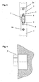
- Figur 1:
- ein Schnappschloss in einer Seitenansicht mit der Falle 1, dem Stulp 2 sowie dem Schlosskasten 3,
- Figur 2:
- das Schnappschloss in montierter Situation innerhalb eines Türblattes 4 in einer Seitenansicht, wobei das Türblatt 4 mit einem Ausbruch dargestellt ist, um den Schlosskasten 3, den im Türblatt 4 eingelassenen Stulp 2, die Stirnseite 4a des Türblattes 4 sowie die Falle 1 erkennen zu können. Der Stulp 2 und das Türblatt 4 bilden eine Ebene an der Stirnseite 4a des Türblattes 4, an der die Falle 1 aus dem Schlosskasten 3 sowie dem Stulp 2 herausragt. Weiterhin ist in der
Figur 2 eine Ansichtenrichtung Y angegeben, - Figur 3:
- das Schnappschloss aus Sicht der Ansichtenrichtung Y aus
Figur 2 in einer Vorderansicht, bei der der Stulp 2 mit zwei Befestigungsschrauben 2a am Türblatt 4 befestigt ist, sowie zwei weiteren Schrauben 5, mit denen der Stulp an den Schlosskasten befestigt ist; weiterhin ist die Falle 1 erkennbar sowie eine Schnittebene X - X, - Figur 4:
- die
Figur 2 , wobei der Fallenausschluss 6 mit einem X angegeben ist, wobei die Angabe X ein maximales Fallenausschlussmaß darstellt, - Figur 5:
- die
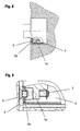
Figur 2 mit einem Teilausbruch, durch den eine Schraube 5, ein Durchzug 3a sowie eine Einstellschraube 7 und ein Fallenflansch 1a angegeben sind, - Figur 6:
- den Teilausbruch aus
Figur 5 vergrößert dargestellt, bei dem der Schlosskasten 3, die Schraube 5, der Stulp 2 sowie die Einstellschraube 7 und der Fallenflansch 1a zu erkennen sind. Die Schraube 5 ist in den Durchzug 3a eingeschraubt, wodurch der Stulp 2 am Schlosskasten 3 befestigt ist, - Figur 7:
- das Innere des Schlosskastens 3 ohne Deckel, wobei der Stulp 2 im Vollschnitt sowie die Falle 1 mit einem Teilausbruch angegeben ist, an der der Fallenflansch 1a angebracht ist. Es ist die Lage der Feder 8, der Einstellschraube 7 sowie die der beiden Schrauben 5 erkennbar, wobei die in dieser Ansicht untere Schraube 5 im Schnitt dargestellt ist, welche im Durchzug 3a eingeschraubt ist,
- Figur 8:
- ein Detail aus
Figur 7 vergrößert dargestellt, wobei die Einstellschraube 7 am Fallenflansch 1a durch die Drehachse 7d eingeschraubt ist, der Schraubenkopf 7a besitzt eine Freimachung 7b, in der der Durchzug 3a des Schlosskastens 3 sowie die Schraube 5 eindringen, und der Schraubenkopf 7a sich an die Ebene 3b anlehnt. Die Schraube 5 befestigt den Stulp 2 durch den Durchzug 3a am Schlosskasten 3. Die Anschlagsicherung 9 ist gegenüberliegend des Schraubenkopfes 7a der Einstellschraube 7 an dem Gewindeende der Einstellschraube 7 angebracht, - Figur 9:
- die
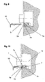
Figur 5 , wobei die Schraube 5 von einem Werkzeug 10 betätigt wird. Ein Teilausbruch stellt das Senkloch 5a für die Schraube 5 sowie den Durchzug 3a und den Schraubenkopf 7a dar, - Figur 10:
- die
Figur 9 ohne die Schraube 5, wobei das Werkzeug 10 durch das Senkloch 5a sowie durch die Gewindebohrung des Durchzuges 3a hindurch in den Schraubenkopf 7a der Einstellschraube 7 eingreift, wobei die Einstellschraube 7 am Fallenflansch 1a eingeschraubt ist, die Bewegachse 1b der Falle 1 ist erkennbar, - Figur 11:
- die
Figur 5 , wobei die Einstellschraube 7 am Fallenflansch 1a derart eingedreht ist, dass ein Fallenausschluss 6a vorhanden ist, welches mit X1 angegeben ist, wobei die Angabe X1 ein minimales Fallenausschlussmaß darstellt, wobei der Fallenflansch 1a an der Anschlagsicherung 9 anliegt. Weiterhin ist der Schraubenkopf 7a mit seiner Anlagefläche 7c dargestellt, - Figur 12:
- die
Figur 5 , wobei die Verstellschraube 7 am Fallenflansch 1 a derart eingedreht ist, dass ein Fallenausschluss 6 vorhanden ist, welches mit X angegeben ist, wobei die Angabe X ein maximales Fallenausschlussmaß darstellt. Der Fallenflansch 1a liegt an der Anlagefläche 7c des Schraubenkopfes 7a an. Die Anschlagsicherung 9 wird vom Fallenflansch 1a nicht beansprucht, - Figur 13:
- die
Figur 10 , jedoch besitzt die Schraube 5 ein Durchgangsloch, durch das ein Werkzeug 10 hindurch die Geometrie des Schraubenkopf 7a der Einstellschraube 7 zur Betätigung erreicht. Die Schraube 5 mit Durchgangsloch befestigt den Stulp 2 am Schlosskasten 3, - Figur 14:
- die
Figur 2 , wobei durch die Schnittebene X - X ausFigur 3 ein Teilausbruch dargestellt ist. In dem Teilausbruch ist ein Mikroschalter 12 mit seiner Kontaktfahne 12a erkennbar, wobei die Kontaktfahne an der Kante 1c der Falle 1 anliegt. Die Datenleitung 11 ragt durch das Türblatt 4 in den Schlosskastens 3 hinein, wobei Einzeladern 11a der Datenleitung 11 an dem Mikroschalter 12 angeschlossen sind. - Das in
Figur 1 in einer Seitenansicht dargestellte Schnappschloss weist einen Schlosskasten 3 auf, der bis an einem Stulp 2 heranragt, wobei auf der gegenüberliegenden Seite des Stulpes 2, von der der Schlosskasten am Stulp 2 heranragt, die Falle 1 aus dem Schlosskasten 3 und durch den Stulp 2 herausragt. In dieser kompletten Bauweise ist das Schnappschloss in eine Tür einzubauen. - Die
Figur 2 stellt die Lage des Schnappschlosses im eingebauten Zustand innerhalb eines Türblattes 4 dar. Das Türblatt 4 besitzt eine Schlosstasche, welche eine Aussparung im Türblatt 4 zur Aufnahme des Schlosskastens 3 darstellt, wobei das Türblatt 4 eine an seiner Stirnseite befindliche Vertiefung vorweist, die zur Aufnahme des Stulpes 2 dient. Der Stulp 2 ist in der Vertiefung des Türblattes 4 derart eingebaut, dass der Stulp 2 und die Stirnseite 4a des Türblattes 4 eine Ebene bilden. Hierdurch steht der Stulp 2 weder der Stirnseite 4a vor, noch liegt der Stulp 2 tiefer in der Vertiefung des Türblattes 4 in Richtung des Schlosskastens 3. Die Stirnseite 4a des Türblattes 4 ist die schmale Seite des Türblattes 4, in der die Schlosstasche für den Schlosskasten 3 sowie die Vertiefung für den Stulp 2 eingearbeitet sind. Die Falle 1 ragt aus dem Schlosskasten 3 durch den Stulp 2 hindurch, wobei die Falle 1 dem Stulp 2 vorsteht. Die Schlosstasche sowie die Vertiefung im Türblatt 4 sind derart ausgelegt, dass sowohl der Stulp 2 als auch der Schlosskasten 3 genügend Platz zum Einbau erhalten. Weiterhin weist dieFigur 2 eine Ansichtenrichtung Y auf. - Bei der
Figur 3 ist die Einbausituation des Schnappschlosses aus der Ansichtenrichtung Y ausFigur 2 dargestellt. Mit den beiden Befestigungsschrauben 2a wird das Schnappschloss am Türblatt 4 befestigt. Die beiden Schrauben 5 dienen der Befestigung des Stulpes 2 am Schlosskasten,
wobei die Falle 1 zwischen den Schrauben 5 angebracht ist. Die Bedeutung der Schnittebene X - X wird inFigur 14 beschrieben. - Die
Figur 4 gibt dieFigur 2 wieder, wobei ein Fallenausschluss 6 in diesem Ausführungsbeispiel mit einem X gekennzeichnet ist. Die Kennzeichnung X gibt ein Fallenausschlussmaß an, welches den Abstand zwischen der Durchtrittsfläche, an der die Falle 1 aus dem Stulp 2 schlosskastenauswärts austritt, und dem Bereich der Falle 1, der am Weitesten von dem Stulp 2 schlosskastenauswärts entfernt ist. - In der
Figur 5 wird dieFigur 2 dargestellt, wobei durch einen Teilausbruch eine der beiden Schrauben 5, ein Durchzug 3a sowie eine Einstellschraube 7, welche in einem Fallenflansch 1a eingeschraubt ist, angegeben sind. Der Fallenflansch 1a besitzt ein Gewinde, welches mit der Einstellschraube 7 korrespondiert. -
Figur 6 zeigt den Teilausbruch aus derFigur 5 in vergrößerter Darstellung. Durch Biegeverfahren sowie Stanzverfahren sind Durchzüge 3a am Schlosskasten 3 angebracht, von denen in derFigur 6 ein Durchzug 3a erkennbar ist. Die Durchzüge besitzen jeweils ein Gewinde, in das jeweils eine Schraube 5 eingeschraubt wird, um den Stulp 2 am Schlosskasten 3 zu befestigen. Die beiden Schrauben 5 sind in derFigur 3 bereits näher erläutert. Weiterhin zeigtFigur 6 die Einstellschraube 7, welche durch einen Fallenflansch 1a hindurchragt. - Bei der
Figur 7 ist das Schnappschloss in einer Seitenansicht derart dargestellt, dass bei dem Schlosskasten 3 die Druckfeder 8 sowie die Falle 1 zu erkennen sind. Dies kann in dieser Ansicht dargestellt werden, da in derFigur 7 der Deckel des Schlosskastens 3 entfernt ist. Durch einen Teilausbruch an der Falle 1 ist zu erkennen, dass der Fallenflansch 1a direkt mit der Falle 1 verbunden ist. Der Teilausbruch sowie der Stulp 2 sind auf einer Ebene im Schnitt dargestellt, bei dem die Einstellschraube 7 sowie eine der beiden Schrauben 5 und der Durchzug 3a erkennbar sind. Die Druckfeder 8 ist derart im Schlosskasten 3 angeordnet, dass sie mit ihren Stirnseiten zwischen der Innenwand des Schlosskastens 3 sowie der Falle 1 auf der Bewegachse der Falle 1 vorgespannt an der Falle 1 und an der Innenwand des Schlosskastens 3 anliegt, wobei die Druckfeder 8 durch eine Bewegung der Falle 1 in Richtung gehäuseeinwärts weiter gespannt wird. - Die
Figur 8 zeigt in einer vergrößerten Darstellung den Teilausbruch aus derFigur 7 . Hier ist zu erkennen, dass die Schraube 5 den Stulp 2 am Durchzug 3a befestigt, wobei der Durchzug 3a durch Biegeverfahren und Stanzverfahren am Schlosskasten 3 angebracht ist. Der Durchzug 3a ragt in eine Freimachung 7b des Schraubenkopf 7a der Einstellschraube 7 ein,
wobei der Schraubenkopf 7a sich an der Ebene 3b anlehnt. Die Einstellschraube 7 wird durch ein Gewinde am Fallenflansch 1a geführt, wobei am gegenüberliegenden Ende des Schraubenkopf 7a am Gewindeende der Einstellschraube 7 eine Anschlagsicherung 9 vorhanden ist. Die Schraube 5, der Durchzug 3a sowie die Einstellschraube 7 und das Gewinde des Fallenflansch 1 a liegen auf derselben Drehachse 7d. - Die
Figur 9 stellt dar, dass mit einem Werkzeug 10 eine Schraube 5, welche den Schraubenkopf 7a abdeckt, aus dem Durchzug 3a herausgeschraubt sowie in den Durchzug 3a hineingeschraubt werden kann, wobei die Schraube 5 durch das Senkloch 5a geführt wird. - Bei der
Figur 10 ist zu erkennen, dass ein Werkzeug 10 durch das Senkloch 5a sowie durch den Durchzug 3a hindurch in die im Schraubenkopf 7a der Einstellschraube 7 vorgesehene Geometrie zur Betätigung der Einstellschraube 7 eingreift. Durch eine Drehbewegung des Werkzeug 10 und somit die Betätigung der Einstellschraube 7 wird die Falle 1 durch das im Fallenflansch 1a befindliche Gewinde auf der Bewegachse 1b geradlinig bewegt. - Die
Figur 11 zeigt dieFigur 5 , wobei eine Einstellung des Fallenausschluss 6a mit einem minimalen Fallenausschlussmaß X1 zu erkennen ist. Bei einem minimalen Fallenausschlussmaß X1 liegt der Fallenflansch 1a an der Anschlagsicherung 9 an, welche am gegenüberliegenden Ende des Schraubenkopf 7a am Gewindeende der Einstellschraube 7 vorhanden ist. Die Anlagefläche 7c des Schraubenkopfes 7a wird bei der minimalen Einstellung des Fallenausschlussmaßes X1 nicht als Anlagefläche von dem Fallenflansch 1a genutzt. - Die
Figur 12 zeigt dieFigur 5 , wobei eine Einstellung des Fallenausschluss 6 mit einem maximalen Fallenausschlussmaß X zu erkennen ist. Bei einem maximalen Fallenausschlussmaß X liegt der Fallenflansch 1a an der Anlagefläche 7c des Schraubenkopfes 7a der Einstellschraube 7 an. Die Anschlagsicherung 9 wird bei der maximalen Einstellung des Fallenausschlussmaßes X nicht als Anlagefläche von dem Fallenflansch 1a genutzt. - Bei der
Figur 13 wird eine Kombination aus denFiguren 10 und11 dargestellt, jedoch besitzt in dieser Ausführungsform die Schraube 5 ein Durchgangsloch, wobei sie im eingeschraubten Zustand den Stulp 2 am Schlosskasten 3 befestigt. Dieses Durchgangsloch ist derart ausgelegt, dass durch dieses Durchgangsloch hindurch mit dem Werkzeug 10 die Geometrie des Schraubenkopfes 7a der Einstellschraube 7 zur Betätigung der Einstellschraube 7 erreicht werden kann. Bei dieser Ausführungsform ist es nicht erforderlich, die relevante Schraube 5 zu entfernen, um mit dem Werkzeug 10 an die Einstellschraube 7 zu gelangen. - Die
Figur 14 zeigt dieFigur 2 , jedoch wird hier die Schnittebene X - X aus derFigur 3 genutzt. Eine Datenleitung 11 ragt durch das Türblatt 4 in den Schlosskasten 3 hinein. Innerhalb des Schlosskastens ist die Datenleitung an ein elektronisches Element angeschlossen, wobei in dieser Ausführungsform ein Mikroschalter 12 mit den Einzeladern 11a angeschlossen ist. Die Kontaktfahne 12a des Mikroschalters 12 hat in dieser Ansicht Kontakt mit der Kante 1c der Falle 1. - Bei der erfindungsgemäßen Ausführungsform des Schnappschlosses bleibt das Schnappschloss während der Einstellung des Fallenausschlusses im Türblatt 4 montiert. Mit einem Werkzeug 10 wird eine Schraube 5, die die Einstellschraube 7 abdeckt, entfernt. Selbstverständlich kann hier auch ein Stopfen eingesetzt werden, der ebenfalls mit einem Werkzeug 10 oder von Hand entfernt werden kann. Nachdem die relevante Schraube 5 entfernt wurde, ist die Einstellschraube 7 für ein Werkzeug 10 und zugänglich, wobei das Werkzeug 10 durch das Senkloch 5a sowie durch den Durchzug 3a hindurch auf die korrespondierende Geometrie des Schraubenkopfes 7a zugreift. Die Einstellschraube 7 besitzt ein Außengewinde, welches mit einem entsprechenden Innengewinde an einem Fallenflansch 1a korrespondiert. Die Einstellschraube besitzt an seinem gegenüberliegenden Ende des Schraubenkopfes 7a eine Anschlagsicherung 9, welche am Außengewinde der Einstellschraube 7 vorhanden ist und dafür sorgt, dass der Fallenflansch 1a nicht von dem Außengewinde der Einstellschraube 7 heruntergedreht werden kann. Die Einstellschraube 7 und das Innengewinde des Fallenflansch 1a besitzen eine gemeinsame Drehachse 7d. Der Fallenflansch 1a ist an der Falle 1 befestigt, wobei die Falle 1 eine Bewegachse 1b vorweist, die parallel zur Drehachse 7d der Einstellschraube 7 verläuft. Wird das Werkzeug 10, welches in die Geometrie des Schraubenkopfes 7a der Einstellschraube 7 eingreift, gedreht, so bewegt sich der Fallenflansch 1a. Durch die direkte Verbindung des Fallenflansches 1a mit der Falle 1 bewegt sich die Falle 1 auf ihrer Bewegachse 1b gehäuseeinwärts oder gehäuseauswärts, welches abhängig von der Drehrichtung des Werkzeug 10 ist. Durch diese Drehbewegung des Werkzeuges 10, welches überwiegend von einem Monteur durchgeführt wird, wird ein minimaler Fallenausschluss 6a mit einem Fallenausschlussmaß X1 derart eingestellt, dass der Fallenflansch 1a soweit gehäuseeinwärts bewegt wird, bis dieser sich an der Anschlagsicherung 9 anlehnt. Ein maximaler Fallenausschluss 6 mit einem Fallenausschlussmaß X wird erzielt, indem das Werkzeug 10 derart gedreht wird, dass die Falle 1 gehäuseauswärts bewegt wird, bis der Fallenflansch 1 a an der Anlagefläche 7c anlehnt. Unterschiedliche Fallenausschlussmaße, welche zwischen dem minimalen Fallenausschlussmaß X1 und dem maximalen Fallenausschlussmaß X liegen, ergeben sich aus der Lage des Fallenflansch 1a, indem dieser Einstellungen einnimmt, bei der der Fallenflansch 1a weder an der Anschlagsicherung 9 noch an der Anlagefläche 7c anliegt.
- Durch die Druckfeder 8 hat die Falle 1 das Bestreben, sich gehäuseauswärts durch den Stulp 2 entlang der Bewegachse 1b geradlinig geführt zu bewegen, da die Druckfeder 8 derart im Schlosskasten 3 angeordnet ist, dass sie mit ihren Stirnseiten zwischen der Innenwand des Schlosskastens 3 sowie der Falle 1 auf der Bewegachse der Falle 1 vorgespannt an der Falle 1 und an der Innenwand des Schlosskastens 3 anliegt.
- Durch die direkte Verbindung des Fallenflansch 1a an der Falle 1 wirkt die Federkraft der Druckfeder 8 ebenfalls durch den Fallenflansch 1a und dessen Innengewinde auf das korrespondierende Außengewinde der Einstellschraube 7 in der gleichen Wirkrichtung, wie bei der Falle 1. Durch die an der Einstellschraube 7 wirkende Federkraft der Duckfeder 8 wird der Schraubenkopf 7a der Einstellschraube 7 gegen die Ebene 3b gedrückt, welches dafür sorgt, dass die Einstellschraube 7 und somit der eingestellte Fallenausschluss der Falle 1 sich nicht selbstständig verstellen kann.
- Es ist auch denkbar, dass die Schraube 5, welche die Einstellschraube 7 abdeckt, eine Durchgangsbohrung besitzt. Bei dieser erfindungsgemäßen Ausführungsform ist es nicht erforderlich, die Schraube 5 zu entfernen, da das Werkzeug 10 durch dieses Durchgangsloch sowie durch den Durchzug 3a hindurch auf die Geometrie des Schraubenkopfes 7a der Einstellschraube 7 zugreifen kann, um anschließend die erforderlichen Drehbewegungen ausüben zu können.
- Selbstverständlich kann auch ein eingesetzter Stopfen eine Durchgangsbohrung besitzen, um mit dem Werkzeug 10 an die Einstellschraube 7 zu gelangen. Bei der Gestaltung der Schraube 5 sowie des Stopfens jeweils mit Durchgangsloch ist die Einstellschraube 7 teilweise abgedeckt.
- Somit ist gewährleistet, dass ein Ausbau des Schnappschlosses aus dem Türblatt zur Einstellung des Fallenausschlusses nicht erforderlich ist.
- Die Datenleitung 11 dient der Statusabfrage sowie der Übermittlung von Informationen sowie Befehlen, die vom Schnappschloss aus sowie zum Schnappschloss hin gesendet werden. Innerhalb des Schlosskastens ist die Datenleitung 11 an ein elektronisches Element angeschlossen, wobei in dieser Ausführungsform ein Mikroschalter 12 mit den Einzeladern 11a angeschlossen ist. Die Kontaktfahne 12a des Mikroschalters 12 hat in dieser Ansicht Kontakt mit der Kante 1c der Falle 1. Selbstverständlich können unterschiedliche elektronische Elemente verwendet werden. Diese elektronischen Elemente können Sensoren sein, die zum Beispiel optische oder induktive Informationen senden sowie empfangen.
-
- 1
- Falle
- 1a
- Fallenflansch
- 1 b
- Bewegachse
- 1 c
- Kante
- 2
- Stulp
- 2a
- Befestigungsschraube
- 3
- Schlosskasten
- 3a
- Durchzug
- 4
- Türblatt
- 4a
- Stirnseite
- 5
- Schraube
- 5a
- Senkloch
- 6
- Fallenausschluss X
- 6a
- Fallenausschluss X1
- X
- maximales Fallenausschlussmaß
- X1
- minimales Fallenausschlussmaß
- 7
- Einstellschraube
- 7a
- Schraubenkopf
- 7b
- Freimachung
- 7c
- Anlagefläche
- 7d
- Drehachse
- 8
- Druckfeder
- 9
- Anschlagsicherung
- 10
- Werkzeug
- 11
- Datenleitung
- 11a
- Einzeladern
- 12
- Mikroschalter
- 12a
- Kontaktfahne
Claims (20)
- Schnappschloss zum Einbau in ein Türblatt (4), mit einem Schlosskasten (3), der an einer Seite einen Stulp (2) aufweist, und einer Falle (1), die aus dem Schlosskasten (3) herausragt und den Stulp (2) durchdringt, wobei das Schnappschloss eine Vorrichtung zur Verstellung des Fallenausschlusses aufweist, dadurch gekennzeichnet, dass die Vorrichtung ohne Ausbau des Schnappschlosses aus dem Türblatt (4) betätigbar ist.
- Schnappschloss nach Anspruch 1 dadurch gekennzeichnet, dass die Vorrichtung eine Einstellschraube (7) aufweist, die mittels eines Werkzeuges (10) am oder durch eine Öffnung im Stulp (2) betätigbar ist.
- Schnappschloss nach Anspruch 2 dadurch gekennzeichnet, dass die Einstellschraube (7) von einer Schraube (5) abgedeckt wird.
- Schnappschloss nach Anspruch 2 dadurch gekennzeichnet, dass die Einstellschraube (7) von einem Stopfen abgedeckt wird.
- Schnappschloss nach Anspruch 3 dadurch gekennzeichnet, dass mindestens eine Schraube (5) den Schlosskasten (3) am Stulp (2) befestigt.
- Schnappschloss nach Anspruch 3 dadurch gekennzeichnet, dass die Schraube (5), mit einem Werkzeug (10) entfernt wird, wodurch die Einstellschraube (7) zur Betätigung zugänglich wird.
- Schnappschloss nach Anspruch 4 dadurch gekennzeichnet, dass ein Stopfen vorzugsweise mit einem Werkzeug (10) oder von Hand entfernt wird, wodurch die Einstellschraube (7) zur Betätigung zugänglich wird.
- Schnappschloss nach Anspruch 3 dadurch gekennzeichnet, dass die Schraube (5), ein Durchgangsloch besitzt, wobei die Einstellschraube (7) teilweise abgedeckt wird.
- Schnappschloss nach Anspruch 6 und/oder 8 dadurch gekennzeichnet, dass die Einstellschraube (7) durch ein Werkzeug (10) betätigt wird.
- Schnappschloss nach Anspruch 2 dadurch gekennzeichnet, dass die Einstellschraube (7) in ein entsprechendes korrespondierendes Gewinde eingreift, welches am Fallenflansch (1a) angeordnet ist.
- Schnappschloss nach Anspruch 10 dadurch gekennzeichnet, dass die Einstellschraube (7) mit dem Werkzeug (10) auf ihrer Drehachse (7d) gedreht wird.
- Schnappschloss nach Anspruch 10 dadurch gekennzeichnet, dass der Fallenflansch (1a) an der Falle (1) angeordnet ist.
- Schnappschloss nach Anspruch 2 dadurch gekennzeichnet, dass die Einstellschraube (7) eine Anschlagsicherung (9) besitzt.
- Schnappschloss nach Anspruch 10 dadurch gekennzeichnet, dass durch die Betätigung der Einstellschraube (7) mit einem Werkzeug (10) die Falle (1) auf einer Bewegachse (1b) gehäuseeinwärts oder gehäuseauswärts bewegt wird.
- Schnappschloss nach Anspruch 11 und 14 dadurch gekennzeichnet, dass die Drehachse (7d) und die Bewegachse (1b) vorzugsweise parallel angeordnet sind.
- Schnappschloss nach Anspruch 14 dadurch gekennzeichnet, dass durch Betätigung der Einstellschraube (7) mit einem Werkzeug (10) ein minimaler Fallenausschluss (X1) eingestellt wird, wobei die Anschlagsicherung (9) als Anschlag für den Fallenflansch (1a) dient.
- Schnappschloss nach Anspruch 14 dadurch gekennzeichnet, dass durch Betätigung der Einstellschraube (7) mit einem Werkzeug (10) ein maximaler Fallenausschluss (X) eingestellt wird, wobei die Anlagefläche (7c) des Schraubenkopfes (7a) der Einstellschraube (7) als Anschlag für den Fallenflansch (1a) dient.
- Schnappschloss nach Anspruch 16 und 17 dadurch gekennzeichnet, dass ein Maß für den Fallenausschluss, welches sich zwischen dem minimalen Fallenausschluss (X1) und dem maximalen Fallenausschluss (X) befindet, derart erzielt wird, dass der Fallenflansch (1 a) zwischen der Anschlagsicherung (9) und der Anlagefläche (7c) eingestellt ist, wobei der Fallenflansch (1a) weder an der Anschlagsicherung (9) noch an der Anlagefläche (7c) des Schraubenkopfes (7a) anliegt.
- Schnappschloss nach einem der vorgenannten Ansprüche dadurch gekennzeichnet, dass ein Schnappschloss mindestens ein elektronisches Element vorweist, welches an einer Datenleitung (11) angeschlossen ist.
- Schnappschloss nach Anspruch 19 dadurch gekennzeichnet, dass die Datenleitung durch das Türblatt (4) zu dem Schlosskasten (3) geführt wird, wobei Einzeladern (11a) der Datenleitung (11) an mindestens ein elektronisches Element des Schnappschlosses angeschlossen ist.
Applications Claiming Priority (1)
| Application Number | Priority Date | Filing Date | Title |
|---|---|---|---|
| DE200710043990 DE102007043990A1 (de) | 2007-09-14 | 2007-09-14 | Schnappschloss |
Publications (3)
| Publication Number | Publication Date |
|---|---|
| EP2037062A2 true EP2037062A2 (de) | 2009-03-18 |
| EP2037062A3 EP2037062A3 (de) | 2009-11-04 |
| EP2037062B1 EP2037062B1 (de) | 2013-05-01 |
Family
ID=40260755
Family Applications (1)
| Application Number | Title | Priority Date | Filing Date |
|---|---|---|---|
| EP08014033.8A Active EP2037062B1 (de) | 2007-09-14 | 2008-08-06 | Schnappschloss |
Country Status (4)
| Country | Link |
|---|---|
| EP (1) | EP2037062B1 (de) |
| CN (1) | CN101387166A (de) |
| DE (1) | DE102007043990A1 (de) |
| ES (1) | ES2423675T3 (de) |
Cited By (3)
| Publication number | Priority date | Publication date | Assignee | Title |
|---|---|---|---|---|
| EP2653637A1 (de) * | 2012-04-20 | 2013-10-23 | Metalux | Einstellbares Einsteckschloss mit schmalem Profil |
| US20210189769A1 (en) * | 2019-12-18 | 2021-06-24 | Schlage Lock Company Llc | Lock and method of adjusting a lock configuration |
| SE544749C2 (en) * | 2018-12-17 | 2022-11-01 | Se Dev Ab | Bolt assembly with bolt guiding member with first and second attachment portions allowing alternating mounting, and door lock arrangement |
Family Cites Families (9)
| Publication number | Priority date | Publication date | Assignee | Title |
|---|---|---|---|---|
| GB678764A (en) * | 1950-05-24 | 1952-09-10 | Erebus Mfg Company Ltd | Latches or catches for doors |
| CH531118A (de) * | 1969-10-08 | 1972-11-30 | Straessler Hans | Türschloss |
| FR2597539B1 (fr) * | 1986-04-18 | 1992-01-24 | Tirard Sa Jean | Ensemble de verrouillage pourvu d'au moins un pene reglable dans le sens de la longueur |
| DE4218733A1 (de) * | 1992-06-06 | 1993-12-09 | Fuhr Carl Gmbh & Co | Falle, insbesondere an Treibstangenbeschlägen |
| US5666830A (en) * | 1994-06-23 | 1997-09-16 | Litvin; Noel | Security lock, with free opening from indoors |
| AU2002223937A1 (en) * | 2000-11-22 | 2002-06-03 | Bryan Michael Risi | A locking mechanism |
| US6655180B2 (en) * | 2001-07-31 | 2003-12-02 | Security People, Inc. | Locker lock with adjustable bolt |
| FR2857047A1 (fr) * | 2003-07-01 | 2005-01-07 | Amonter | Dispositif de securisation d'un acces a une serrure |
| DE10347151A1 (de) * | 2003-10-10 | 2005-05-04 | Fliether Karl Gmbh & Co | Falle, insbesondere Rollenfalle |
-
2007
- 2007-09-14 DE DE200710043990 patent/DE102007043990A1/de active Pending
-
2008
- 2008-08-06 EP EP08014033.8A patent/EP2037062B1/de active Active
- 2008-08-06 ES ES08014033T patent/ES2423675T3/es active Active
- 2008-09-10 CN CNA2008102128409A patent/CN101387166A/zh active Pending
Non-Patent Citations (1)
| Title |
|---|
| None |
Cited By (5)
| Publication number | Priority date | Publication date | Assignee | Title |
|---|---|---|---|---|
| EP2653637A1 (de) * | 2012-04-20 | 2013-10-23 | Metalux | Einstellbares Einsteckschloss mit schmalem Profil |
| FR2989717A1 (fr) * | 2012-04-20 | 2013-10-25 | Metalux | Serrure a mortaiser reglable a profil etroit |
| SE544749C2 (en) * | 2018-12-17 | 2022-11-01 | Se Dev Ab | Bolt assembly with bolt guiding member with first and second attachment portions allowing alternating mounting, and door lock arrangement |
| US20210189769A1 (en) * | 2019-12-18 | 2021-06-24 | Schlage Lock Company Llc | Lock and method of adjusting a lock configuration |
| US12404700B2 (en) * | 2019-12-18 | 2025-09-02 | Schlage Lock Company Llc | Lock and method of adjusting a lock configuration |
Also Published As
| Publication number | Publication date |
|---|---|
| DE102007043990A1 (de) | 2009-03-19 |
| EP2037062B1 (de) | 2013-05-01 |
| ES2423675T3 (es) | 2013-09-23 |
| CN101387166A (zh) | 2009-03-18 |
| EP2037062A3 (de) | 2009-11-04 |
Similar Documents
| Publication | Publication Date | Title |
|---|---|---|
| EP2468989B1 (de) | Schloss für eine ganzglastür | |
| WO1995029314A1 (de) | Verschluss mit variablem schlosseinsatz | |
| EP0175012A1 (de) | Steckschlüsselbetätigbarer, arretierbarer Vorreiberverschluss | |
| EP1071857B1 (de) | Einbausicherung und schlüssel für ein sicherheitsschloss | |
| EP2037062B1 (de) | Schnappschloss | |
| EP2796645A2 (de) | Riegelschloss eines Möbels | |
| EP2754790B1 (de) | Element mit selbstzentrierendem Beschlag für Fenster oder Türen | |
| EP2692968B1 (de) | Knaufzylinder | |
| EP0175211A1 (de) | Steckschlüsselbetätigbarer, arretierbarer Vorreiberverschluss | |
| EP2264267A2 (de) | Schloss | |
| WO2007028604A1 (de) | Schliesszylinder für insbesondere an fahrzeugen vollziehbare funktionen | |
| DE3010115A1 (de) | Arretierungsvorrichtung fuer vorreiberverschluesse, stangenverschluesse u.dgl. | |
| EP0585735B1 (de) | Schlosssicherung für Sicherheitsschliess-Zylinder | |
| EP1580354A2 (de) | Beschlag | |
| EP3514302B1 (de) | Türbeschlag und verfahren zum montieren eines türbeschlags | |
| EP3553260B1 (de) | Falleneinsatz mit tagstellung zur bedingten freigabe einer schlossfalle eines türschlossmechanismus | |
| DE202015102071U1 (de) | Türklinke mit einer Freilauffunktion | |
| EP3162991B1 (de) | Schliessvorrichtung für eine abdeckung, verschliessbares abdecksystem | |
| DE8008675U1 (de) | Mit einem schliesszylinder ausgeruestetes bauelement | |
| EP0036480A1 (de) | Ganzglasflügel-Beschlag | |
| DE19725962A1 (de) | Türverschluß | |
| DE10327267A1 (de) | Notentriegelungsvorrichtung | |
| DE102014110970B3 (de) | Schließzylinderanordnung | |
| EP1263010A1 (de) | Seilzug-Schlüsselschalter | |
| DE19809900B4 (de) | Vorrichtung zur Sicherung von Fenster, Fenstertüren und Türen gegen gewaltsames Öffnen |
Legal Events
| Date | Code | Title | Description |
|---|---|---|---|
| PUAI | Public reference made under article 153(3) epc to a published international application that has entered the european phase |
Free format text: ORIGINAL CODE: 0009012 |
|
| AK | Designated contracting states |
Kind code of ref document: A2 Designated state(s): AT BE BG CH CY CZ DE DK EE ES FI FR GB GR HR HU IE IS IT LI LT LU LV MC MT NL NO PL PT RO SE SI SK TR |
|
| AX | Request for extension of the european patent |
Extension state: AL BA MK RS |
|
| PUAL | Search report despatched |
Free format text: ORIGINAL CODE: 0009013 |
|
| AK | Designated contracting states |
Kind code of ref document: A3 Designated state(s): AT BE BG CH CY CZ DE DK EE ES FI FR GB GR HR HU IE IS IT LI LT LU LV MC MT NL NO PL PT RO SE SI SK TR |
|
| AX | Request for extension of the european patent |
Extension state: AL BA MK RS |
|
| 17P | Request for examination filed |
Effective date: 20100504 |
|
| AKX | Designation fees paid |
Designated state(s): AT BE BG CH CY CZ DE DK EE ES FI FR GB GR HR HU IE IS IT LI LT LU LV MC MT NL NO PL PT RO SE SI SK TR |
|
| 17Q | First examination report despatched |
Effective date: 20100623 |
|
| RAP1 | Party data changed (applicant data changed or rights of an application transferred) |
Owner name: DORMA GMBH + CO. KG |
|
| GRAP | Despatch of communication of intention to grant a patent |
Free format text: ORIGINAL CODE: EPIDOSNIGR1 |
|
| GRAS | Grant fee paid |
Free format text: ORIGINAL CODE: EPIDOSNIGR3 |
|
| GRAA | (expected) grant |
Free format text: ORIGINAL CODE: 0009210 |
|
| AK | Designated contracting states |
Kind code of ref document: B1 Designated state(s): AT BE BG CH CY CZ DE DK EE ES FI FR GB GR HR HU IE IS IT LI LT LU LV MC MT NL NO PL PT RO SE SI SK TR |
|
| REG | Reference to a national code |
Ref country code: GB Ref legal event code: FG4D Free format text: NOT ENGLISH |
|
| REG | Reference to a national code |
Ref country code: AT Ref legal event code: REF Ref document number: 610055 Country of ref document: AT Kind code of ref document: T Effective date: 20130515 Ref country code: CH Ref legal event code: EP |
|
| REG | Reference to a national code |
Ref country code: IE Ref legal event code: FG4D Free format text: LANGUAGE OF EP DOCUMENT: GERMAN |
|
| REG | Reference to a national code |
Ref country code: DE Ref legal event code: R096 Ref document number: 502008009823 Country of ref document: DE Effective date: 20130627 |
|
| REG | Reference to a national code |
Ref country code: CH Ref legal event code: NV Representative=s name: BOVARD AG, CH |
|
| REG | Reference to a national code |
Ref country code: NL Ref legal event code: T3 |
|
| REG | Reference to a national code |
Ref country code: ES Ref legal event code: FG2A Ref document number: 2423675 Country of ref document: ES Kind code of ref document: T3 Effective date: 20130923 |
|
| REG | Reference to a national code |
Ref country code: LT Ref legal event code: MG4D |
|
| PG25 | Lapsed in a contracting state [announced via postgrant information from national office to epo] |
Ref country code: IS Free format text: LAPSE BECAUSE OF FAILURE TO SUBMIT A TRANSLATION OF THE DESCRIPTION OR TO PAY THE FEE WITHIN THE PRESCRIBED TIME-LIMIT Effective date: 20130901 Ref country code: PT Free format text: LAPSE BECAUSE OF FAILURE TO SUBMIT A TRANSLATION OF THE DESCRIPTION OR TO PAY THE FEE WITHIN THE PRESCRIBED TIME-LIMIT Effective date: 20130902 Ref country code: NO Free format text: LAPSE BECAUSE OF FAILURE TO SUBMIT A TRANSLATION OF THE DESCRIPTION OR TO PAY THE FEE WITHIN THE PRESCRIBED TIME-LIMIT Effective date: 20130801 Ref country code: FI Free format text: LAPSE BECAUSE OF FAILURE TO SUBMIT A TRANSLATION OF THE DESCRIPTION OR TO PAY THE FEE WITHIN THE PRESCRIBED TIME-LIMIT Effective date: 20130501 Ref country code: SI Free format text: LAPSE BECAUSE OF FAILURE TO SUBMIT A TRANSLATION OF THE DESCRIPTION OR TO PAY THE FEE WITHIN THE PRESCRIBED TIME-LIMIT Effective date: 20130501 Ref country code: SE Free format text: LAPSE BECAUSE OF FAILURE TO SUBMIT A TRANSLATION OF THE DESCRIPTION OR TO PAY THE FEE WITHIN THE PRESCRIBED TIME-LIMIT Effective date: 20130501 Ref country code: LT Free format text: LAPSE BECAUSE OF FAILURE TO SUBMIT A TRANSLATION OF THE DESCRIPTION OR TO PAY THE FEE WITHIN THE PRESCRIBED TIME-LIMIT Effective date: 20130501 Ref country code: GR Free format text: LAPSE BECAUSE OF FAILURE TO SUBMIT A TRANSLATION OF THE DESCRIPTION OR TO PAY THE FEE WITHIN THE PRESCRIBED TIME-LIMIT Effective date: 20130802 |
|
| PGFP | Annual fee paid to national office [announced via postgrant information from national office to epo] |
Ref country code: CH Payment date: 20130821 Year of fee payment: 6 Ref country code: NL Payment date: 20130815 Year of fee payment: 6 |
|
| PG25 | Lapsed in a contracting state [announced via postgrant information from national office to epo] |
Ref country code: PL Free format text: LAPSE BECAUSE OF FAILURE TO SUBMIT A TRANSLATION OF THE DESCRIPTION OR TO PAY THE FEE WITHIN THE PRESCRIBED TIME-LIMIT Effective date: 20130501 Ref country code: BG Free format text: LAPSE BECAUSE OF FAILURE TO SUBMIT A TRANSLATION OF THE DESCRIPTION OR TO PAY THE FEE WITHIN THE PRESCRIBED TIME-LIMIT Effective date: 20130801 Ref country code: CY Free format text: LAPSE BECAUSE OF FAILURE TO SUBMIT A TRANSLATION OF THE DESCRIPTION OR TO PAY THE FEE WITHIN THE PRESCRIBED TIME-LIMIT Effective date: 20130501 Ref country code: HR Free format text: LAPSE BECAUSE OF FAILURE TO SUBMIT A TRANSLATION OF THE DESCRIPTION OR TO PAY THE FEE WITHIN THE PRESCRIBED TIME-LIMIT Effective date: 20130501 |
|
| PG25 | Lapsed in a contracting state [announced via postgrant information from national office to epo] |
Ref country code: LV Free format text: LAPSE BECAUSE OF FAILURE TO SUBMIT A TRANSLATION OF THE DESCRIPTION OR TO PAY THE FEE WITHIN THE PRESCRIBED TIME-LIMIT Effective date: 20130501 |
|
| PG25 | Lapsed in a contracting state [announced via postgrant information from national office to epo] |
Ref country code: SK Free format text: LAPSE BECAUSE OF FAILURE TO SUBMIT A TRANSLATION OF THE DESCRIPTION OR TO PAY THE FEE WITHIN THE PRESCRIBED TIME-LIMIT Effective date: 20130501 Ref country code: EE Free format text: LAPSE BECAUSE OF FAILURE TO SUBMIT A TRANSLATION OF THE DESCRIPTION OR TO PAY THE FEE WITHIN THE PRESCRIBED TIME-LIMIT Effective date: 20130501 Ref country code: CZ Free format text: LAPSE BECAUSE OF FAILURE TO SUBMIT A TRANSLATION OF THE DESCRIPTION OR TO PAY THE FEE WITHIN THE PRESCRIBED TIME-LIMIT Effective date: 20130501 Ref country code: DK Free format text: LAPSE BECAUSE OF FAILURE TO SUBMIT A TRANSLATION OF THE DESCRIPTION OR TO PAY THE FEE WITHIN THE PRESCRIBED TIME-LIMIT Effective date: 20130501 |
|
| PGFP | Annual fee paid to national office [announced via postgrant information from national office to epo] |
Ref country code: BE Payment date: 20130823 Year of fee payment: 6 |
|
| PG25 | Lapsed in a contracting state [announced via postgrant information from national office to epo] |
Ref country code: IT Free format text: LAPSE BECAUSE OF FAILURE TO SUBMIT A TRANSLATION OF THE DESCRIPTION OR TO PAY THE FEE WITHIN THE PRESCRIBED TIME-LIMIT Effective date: 20130501 Ref country code: RO Free format text: LAPSE BECAUSE OF FAILURE TO SUBMIT A TRANSLATION OF THE DESCRIPTION OR TO PAY THE FEE WITHIN THE PRESCRIBED TIME-LIMIT Effective date: 20130501 |
|
| PLBE | No opposition filed within time limit |
Free format text: ORIGINAL CODE: 0009261 |
|
| STAA | Information on the status of an ep patent application or granted ep patent |
Free format text: STATUS: NO OPPOSITION FILED WITHIN TIME LIMIT |
|
| 26N | No opposition filed |
Effective date: 20140204 |
|
| GBPC | Gb: european patent ceased through non-payment of renewal fee |
Effective date: 20130806 |
|
| PG25 | Lapsed in a contracting state [announced via postgrant information from national office to epo] |
Ref country code: MC Free format text: LAPSE BECAUSE OF FAILURE TO SUBMIT A TRANSLATION OF THE DESCRIPTION OR TO PAY THE FEE WITHIN THE PRESCRIBED TIME-LIMIT Effective date: 20130501 |
|
| REG | Reference to a national code |
Ref country code: DE Ref legal event code: R097 Ref document number: 502008009823 Country of ref document: DE Effective date: 20140204 |
|
| REG | Reference to a national code |
Ref country code: IE Ref legal event code: MM4A |
|
| PG25 | Lapsed in a contracting state [announced via postgrant information from national office to epo] |
Ref country code: GB Free format text: LAPSE BECAUSE OF NON-PAYMENT OF DUE FEES Effective date: 20130806 Ref country code: IE Free format text: LAPSE BECAUSE OF NON-PAYMENT OF DUE FEES Effective date: 20130806 |
|
| PGFP | Annual fee paid to national office [announced via postgrant information from national office to epo] |
Ref country code: ES Payment date: 20140826 Year of fee payment: 7 Ref country code: AT Payment date: 20140611 Year of fee payment: 7 Ref country code: FR Payment date: 20140821 Year of fee payment: 7 |
|
| REG | Reference to a national code |
Ref country code: DE Ref legal event code: R081 Ref document number: 502008009823 Country of ref document: DE Owner name: DORMAKABA DEUTSCHLAND GMBH, DE Free format text: FORMER OWNER: DORMA GMBH & CO. KG, 58256 ENNEPETAL, DE Effective date: 20141211 Ref country code: DE Ref legal event code: R081 Ref document number: 502008009823 Country of ref document: DE Owner name: DORMA DEUTSCHLAND GMBH, DE Free format text: FORMER OWNER: DORMA GMBH & CO. KG, 58256 ENNEPETAL, DE Effective date: 20141211 |
|
| REG | Reference to a national code |
Ref country code: FR Ref legal event code: CJ Effective date: 20150206 |
|
| REG | Reference to a national code |
Ref country code: NL Ref legal event code: V1 Effective date: 20150301 |
|
| REG | Reference to a national code |
Ref country code: CH Ref legal event code: PL |
|
| REG | Reference to a national code |
Ref country code: ES Ref legal event code: PC2A Owner name: DORMA DEUTSCHLAND GMBH Effective date: 20150415 |
|
| PG25 | Lapsed in a contracting state [announced via postgrant information from national office to epo] |
Ref country code: LI Free format text: LAPSE BECAUSE OF NON-PAYMENT OF DUE FEES Effective date: 20140831 Ref country code: NL Free format text: LAPSE BECAUSE OF NON-PAYMENT OF DUE FEES Effective date: 20150301 Ref country code: BE Free format text: LAPSE BECAUSE OF NON-PAYMENT OF DUE FEES Effective date: 20140831 Ref country code: CH Free format text: LAPSE BECAUSE OF NON-PAYMENT OF DUE FEES Effective date: 20140831 |
|
| REG | Reference to a national code |
Ref country code: DE Ref legal event code: R082 Ref document number: 502008009823 Country of ref document: DE Representative=s name: BALDER IP LAW, S.L., ES |
|
| PG25 | Lapsed in a contracting state [announced via postgrant information from national office to epo] |
Ref country code: TR Free format text: LAPSE BECAUSE OF FAILURE TO SUBMIT A TRANSLATION OF THE DESCRIPTION OR TO PAY THE FEE WITHIN THE PRESCRIBED TIME-LIMIT Effective date: 20130501 Ref country code: MT Free format text: LAPSE BECAUSE OF FAILURE TO SUBMIT A TRANSLATION OF THE DESCRIPTION OR TO PAY THE FEE WITHIN THE PRESCRIBED TIME-LIMIT Effective date: 20130501 |
|
| PG25 | Lapsed in a contracting state [announced via postgrant information from national office to epo] |
Ref country code: HU Free format text: LAPSE BECAUSE OF FAILURE TO SUBMIT A TRANSLATION OF THE DESCRIPTION OR TO PAY THE FEE WITHIN THE PRESCRIBED TIME-LIMIT; INVALID AB INITIO Effective date: 20080806 Ref country code: LU Free format text: LAPSE BECAUSE OF NON-PAYMENT OF DUE FEES Effective date: 20130806 |
|
| REG | Reference to a national code |
Ref country code: AT Ref legal event code: PC Ref document number: 610055 Country of ref document: AT Kind code of ref document: T Owner name: DORMA DEUTSCHLAND GMBH, DE Effective date: 20160122 |
|
| REG | Reference to a national code |
Ref country code: AT Ref legal event code: MM01 Ref document number: 610055 Country of ref document: AT Kind code of ref document: T Effective date: 20150806 |
|
| PG25 | Lapsed in a contracting state [announced via postgrant information from national office to epo] |
Ref country code: AT Free format text: LAPSE BECAUSE OF NON-PAYMENT OF DUE FEES Effective date: 20150806 |
|
| REG | Reference to a national code |
Ref country code: FR Ref legal event code: ST Effective date: 20160429 |
|
| PG25 | Lapsed in a contracting state [announced via postgrant information from national office to epo] |
Ref country code: FR Free format text: LAPSE BECAUSE OF NON-PAYMENT OF DUE FEES Effective date: 20150831 |
|
| REG | Reference to a national code |
Ref country code: ES Ref legal event code: FD2A Effective date: 20160927 |
|
| PG25 | Lapsed in a contracting state [announced via postgrant information from national office to epo] |
Ref country code: ES Free format text: LAPSE BECAUSE OF NON-PAYMENT OF DUE FEES Effective date: 20150807 |
|
| REG | Reference to a national code |
Ref country code: DE Ref legal event code: R082 Ref document number: 502008009823 Country of ref document: DE Representative=s name: BALDER IP LAW, S.L., ES Ref country code: DE Ref legal event code: R081 Ref document number: 502008009823 Country of ref document: DE Owner name: DORMAKABA DEUTSCHLAND GMBH, DE Free format text: FORMER OWNER: DORMA DEUTSCHLAND GMBH, 58256 ENNEPETAL, DE |
|
| PGFP | Annual fee paid to national office [announced via postgrant information from national office to epo] |
Ref country code: DE Payment date: 20250820 Year of fee payment: 18 |