EP2037062A2 - Serrure à encliquetage - Google Patents
Serrure à encliquetage Download PDFInfo
- Publication number
- EP2037062A2 EP2037062A2 EP08014033A EP08014033A EP2037062A2 EP 2037062 A2 EP2037062 A2 EP 2037062A2 EP 08014033 A EP08014033 A EP 08014033A EP 08014033 A EP08014033 A EP 08014033A EP 2037062 A2 EP2037062 A2 EP 2037062A2
- Authority
- EP
- European Patent Office
- Prior art keywords
- snap lock
- adjusting screw
- screw
- trap
- lock according
- Prior art date
- Legal status (The legal status is an assumption and is not a legal conclusion. Google has not performed a legal analysis and makes no representation as to the accuracy of the status listed.)
- Granted
Links
Images


Classifications
-
- E—FIXED CONSTRUCTIONS
- E05—LOCKS; KEYS; WINDOW OR DOOR FITTINGS; SAFES
- E05B—LOCKS; ACCESSORIES THEREFOR; HANDCUFFS
- E05B63/00—Locks or fastenings with special structural characteristics
- E05B63/06—Locks or fastenings with special structural characteristics with lengthwise-adjustable bolts ; with adjustable backset, i.e. distance from door edge
-
- E—FIXED CONSTRUCTIONS
- E05—LOCKS; KEYS; WINDOW OR DOOR FITTINGS; SAFES
- E05B—LOCKS; ACCESSORIES THEREFOR; HANDCUFFS
- E05B47/00—Operating or controlling locks or other fastening devices by electric or magnetic means
- E05B2047/0048—Circuits, feeding, monitoring
- E05B2047/0067—Monitoring
- E05B2047/0069—Monitoring bolt position
-
- E—FIXED CONSTRUCTIONS
- E05—LOCKS; KEYS; WINDOW OR DOOR FITTINGS; SAFES
- E05B—LOCKS; ACCESSORIES THEREFOR; HANDCUFFS
- E05B63/00—Locks or fastenings with special structural characteristics
- E05B63/0056—Locks with adjustable or exchangeable lock parts
-
- E—FIXED CONSTRUCTIONS
- E05—LOCKS; KEYS; WINDOW OR DOOR FITTINGS; SAFES
- E05C—BOLTS OR FASTENING DEVICES FOR WINGS, SPECIALLY FOR DOORS OR WINDOWS
- E05C1/00—Fastening devices with bolts moving rectilinearly
- E05C1/08—Fastening devices with bolts moving rectilinearly with latching action
-
- E—FIXED CONSTRUCTIONS
- E05—LOCKS; KEYS; WINDOW OR DOOR FITTINGS; SAFES
- E05C—BOLTS OR FASTENING DEVICES FOR WINGS, SPECIALLY FOR DOORS OR WINDOWS
- E05C19/00—Other devices specially designed for securing wings, e.g. with suction cups
- E05C19/02—Automatic catches, i.e. released by pull or pressure on the wing
- E05C19/028—Automatic catches, i.e. released by pull or pressure on the wing with sliding bolt(s)
Definitions
- the invention relates to a snap lock in which the setting of a trap exclusion is performed by a device without having to remove the latch from the door and then reinstall.
- the invention provides that a device without removal of the snap lock from the door panel is actuated, wherein the setting of the trap exclusion is made by the device.
- This has the advantage of allowing the installer in a simple manner with little effort setting the trap exclusion.
- the adjustment requires a control that can be performed directly, with a correction of the adjustment can be made immediately, without having to remove the latch from the door leaf, which brings a significant time savings for the fitter.
- a further improvement is achieved in that the device has an adjusting screw which can be actuated by means of a tool on or through an opening in the forend. This allows the fitter to make the setting with a conventional tool.
- the adjusting screw is covered by a screw or a plug. This prevents manipulation.
- Another advantage is that at least one screw attaches the lock case to the forend. As a result, the fastening of the lock case is ensured on the forend, the screw also occupies the covering function of the adjusting screw.
- the screw which covers the adjusting screw is removed with a tool, whereby the adjusting screw is released for actuation.
- the installer has the ability to remove the screw with a single tool and to make an adjustment of the case exclusion on the device and thus on the adjusting screw.
- the screw which covers the adjusting screw has a through hole.
- the adjusting screw is partially covered, but the fitter can press directly with a tool, the adjustment without having to remove another screw before.
- the through hole is designed so that the tool passes through this through hole and through the passage to the head of the adjusting screw.
- the adjusting screw engages in a corresponding corresponding thread, which is attached to the trap flange. As a result, the adjusting screw is held and guided in the position of use.
- the advantage is that the trap flange is attached to the trap. Thus, the rotational movement of the adjusting screw is transmitted via the flange on the case.
- the adjusting screw has a stop safeguard. This ensures that the adjusting screw is not unscrewed from the trap flange.
- Another advantage is that the operation of the adjusting screw with a tool, the case is moved on a moving axis housing inward or outward.
- the adjusting screw which is a rotary movement about the axis of rotation of the adjusting screw, the direction of adjustment of the trap exclusion is limited to two directions which extend on the axis of movement inwardly and outwardly of the housing.
- the axis of rotation and the axis of movement are preferably arranged in parallel.
- the stop guard serves as a stop for the trap flange. It is thereby ensured that the trap provides a trap exclusion to ensure the function of locking the corresponding door in which the latch is installed by securely engaging the latch in a corresponding door opener.
- a maximum trap exclusion can be adjusted by operating the adjusting screw with a tool, wherein the contact surface of the screw head of the adjusting screw serves as a stop for the trap flange. This is necessary in order to be able to bridge distances between the door and the frame in which the corresponding door opener is present.
- a snap lock has at least one electronic element connected to a data line. This allows status requests and command signals to and from the latch.
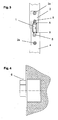
- FIG. 1 in a side view snap lock has a lock case 3, which projects up to a cuff 2, wherein on the opposite side of the Stulpes 2, of which the lock case on the forend 2, the latch 1 protrudes from the lock case 3 and through the forend 2 ,
- the snap lock In this complete design, the snap lock must be installed in a door.
- the door leaf 4 has a lock pocket, which is a recess in the door leaf 4 for receiving the lock case 3, wherein the door panel 4 has a recess located on its front side, which is for receiving the Stulpes 2 serves.
- the forend 2 is installed in the recess of the door leaf 4 such that the forend 2 and the end face 4 a of the door leaf 4 form a plane.
- the faceplate 2 is neither the front side 4a, nor is the forend 2 deeper in the recess of the door leaf 4 in the direction of the lock box 3.
- the front side 4a of the door leaf 4 is the narrow side of the door leaf 4, in which the lock pocket for the lock case 3 and the recess for the forend 2 are incorporated.
- the case 1 protrudes from the lock case 3 through the face plate 2, the case 1 protruding from the face plate 2.
- the lock pocket and the recess in the door leaf 4 are designed such that both the face plate 2 and the lock case 3 receive sufficient space for installation. Furthermore, the FIG. 2 a view direction Y on.
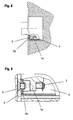
- FIG. 3 is the installation situation of the snap lock from the direction of view Y from FIG. 2 shown.
- the snap lock is fastened to the door leaf 4 with the two fastening screws 2a.
- the two screws 5 are used to attach the Stulpes 2 to the lock case, wherein the case 1 is mounted between the screws 5.
- the meaning of the section plane X - X is given in FIG. 14 described.
- FIG. 4 give the FIG. 2 again, with a trap exclusion 6 is marked in this embodiment with an X.
- the mark X indicates a trap exclusion measure which is the distance between the passage area at which the trap 1 exits the lock box 2 outward and the area of the trap 1 which is furthest away from the lock box 2.
- FIG. 5 will the FIG. 2 represented by a partial eruption one of the two screws 5, a passage 3a and an adjusting screw 7, which is screwed into a latch flange 1a, are indicated.
- the latch flange 1a has a thread which corresponds to the adjusting screw 7.
- FIG. 6 shows the partial breakout from the FIG. 5 in an enlarged view.
- bending process and punching processes are 3a on the lock case 3 are mounted, of which in the FIG. 6 a passage 3a is visible.
- the passages each have a thread, in each of which a screw 5 is screwed to secure the forend 2 on the lock case 3.
- the two screws 5 are in the FIG. 3 already closer explained.
- FIG. 6 the adjusting screw 7, which protrudes through a latch flange 1a.
- the snap lock is shown in a side view such that in the lock case 3, the compression spring 8 and the case 1 can be seen.
- This can be represented in this view, as in the FIG. 7 the lid of the lock case 3 is removed.
- the trap flange 1a is connected directly to the trap 1.
- the partial eruption and the forend 2 are shown on a plane in section, in which the adjusting screw 7 and one of the two screws 5 and the passage 3a can be seen.
- the compression spring 8 is arranged in the lock case 3, that it is biased with its end faces between the inner wall of the lock case 3 and the case 1 on the axis of movement of the case 1 on the case 1 and on the inner wall of the lock case 3, wherein the compression spring 8 by a movement of the case 1 in the direction of the housing further stretched.
- FIG. 8 shows in an enlarged view the partial breakout of the FIG. 7 ,
- the screw 5 secures the forend 2 to the passage 3a, the passage 3a being attached to the lock case 3 by bending and punching methods.
- the passage 3a protrudes into a clearance 7b of the screw head 7a of the adjusting screw 7, wherein the screw head 7a is based on the plane 3b.
- the adjusting screw 7 is guided by a thread on the latch flange 1a, wherein at the opposite end of the screw head 7a at the threaded end of the adjusting screw 7 a stop safeguard 9 is present.
- the screw 5, the passage 3a and the adjusting screw 7 and the thread of the trap flange 1 a lie on the same axis of rotation 7d.
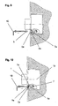
- FIG. 9 shows that with a tool 10, a screw 5, which covers the screw head 7a, unscrewed from the passage 3a and can be screwed into the passage 3a, wherein the screw 5 is guided by the countersunk hole 5a.
- FIG. 10 It can be seen that a tool 10 engages through the countersunk hole 5a and through the passage 3a into the geometry provided in the screw head 7a of the adjusting screw 7 for actuating the adjusting screw 7.
- the case 1 By a rotary movement of the tool 10 and thus the operation of the adjusting screw 7, the case 1 is moved in a straight line by the thread located in the latch flange 1a on the moving axis 1b.
- FIG. 11 show the FIG. 5 wherein an adjustment of the trap exclusion 6a can be seen with a minimum trap exclusion dimension X1.
- the trap flange 1a bears against the stop securing device 9, which is present at the opposite end of the screw head 7a at the threaded end of the adjusting screw 7.
- the contact surface 7c of the screw head 7a is not used as a contact surface of the trap flange 1a at the minimum setting of the trap exclusion dimension X1.
- FIG. 12 show the FIG. 5 wherein an adjustment of the trap exclusion 6 with a maximum trap exclusion dimension X can be seen.
- the trap flange 1a bears against the contact surface 7c of the screw head 7a of the adjusting screw 7.
- the stop safeguard 9 is not used at the maximum setting of the trap exclusion dimension X as a contact surface of the trap flange 1a.
- the screw 5 has a through hole, wherein it secures the forend 2 on the lock case 3 in the screwed state.
- This through hole is designed such that through this through hole with the tool 10, the Geometry of the screw head 7a of the adjusting screw 7 for actuating the adjusting screw 7 can be achieved. In this embodiment, it is not necessary to remove the relevant screw 5 in order to reach the adjusting screw 7 with the tool 10.
- FIG. 14 show the FIG. 2 However, here is the section plane X - X from the FIG. 3 used.
- a data line 11 protrudes through the door leaf 4 into the lock case 3.
- the data line is connected to an electronic element, in which embodiment a microswitch 12 is connected to the individual wires 11a.
- the contact lug 12 a of the microswitch 12 has contact with the edge 1 c of the case 1 in this view.
- the snap lock remains mounted during the setting of the trap exclusion in the door leaf 4.
- a screw 5 which covers the adjusting screw 7, removed.
- a plug can be used, which can also be removed with a tool 10 or by hand.
- the adjusting screw 7 for a tool 10 and accessible wherein the tool 10 accesses through the countersunk hole 5a and through the passage 3a through the corresponding geometry of the screw head 7a.
- the adjusting screw 7 has an external thread which corresponds to a corresponding internal thread on a latch flange 1a.
- the adjusting screw has at its opposite end of the screw head 7a an abutment 9, which is present on the external thread of the adjusting screw 7 and ensures that the latch flange 1a can not be turned down by the external thread of the adjusting screw 7.
- the adjusting screw 7 and the internal thread of the latch flange 1a have a common axis of rotation 7d.
- the latch flange 1a is attached to the latch 1, the latch 1 having a moving axis 1b parallel to the axis of rotation 7d of the adjusting screw 7 runs. If the tool 10, which engages in the geometry of the screw head 7a of the adjusting screw 7, is rotated, then the latch flange 1a moves.
- a minimal trap exclusion 6a is set with a trap exclusion dimension X1 such that the trap flange 1a is moved inward of the housing until it leans against the stop safeguard 9.
- a maximum trap exclusion 6 with a trap exclusion dimension X is achieved by rotating the tool 10 such that the trap 1 is moved outwardly of the housing until the trap flange 1 a bears against the contact surface 7c.
- the case 1 has the desire to move outwardly led by the forend 2 along the axis of movement 1b rectilinear, since the compression spring 8 is arranged in the lock case 3, that they with their end faces between the inner wall of the lock case 3 and the Trap 1 biased on the axis of movement of the case 1 on the case 1 and on the inner wall of the lock case 3 is applied.
- the spring force of the compression spring 8 also acts through the latch flange 1a and its internal thread on the corresponding external thread of the adjusting screw 7 in the same direction of action, as in the case 1.
- the screw head 7a of the adjusting screw 7 is pressed against the plane 3b, which ensures that the adjusting screw 7 and thus the set case exclusion of the case 1 can not adjust itself.
- the screw 5, which covers the adjusting screw 7 has a through hole.
- the tool 10 can access the geometry of the screw head 7a of the adjusting screw 7 through this through-hole as well as through the passage 3a, in order subsequently to be able to exert the required rotational movements.
- an inserted plug may have a through hole to reach with the tool 10 to the adjusting screw 7.
- the adjusting screw 7 is partially covered.
- the data line 11 serves the status query and the transmission of information and commands that are sent from the snap lock and the latch.
- the data line 11 is connected to an electronic element, in which embodiment a microswitch 12 is connected to the individual wires 11a.
- the contact lug 12a of the microswitch 12 has in this view contact with the edge 1c of the case 1.
- electronic elements may be sensors that, for example, transmit and receive optical or inductive information.
Landscapes
- Engineering & Computer Science (AREA)
- Structural Engineering (AREA)
- Lock And Its Accessories (AREA)
- Closing And Opening Devices For Wings, And Checks For Wings (AREA)
- Connection Of Plates (AREA)
- Patch Boards (AREA)
- Casings For Electric Apparatus (AREA)
- Snaps, Bayonet Connections, Set Pins, And Snap Rings (AREA)
Applications Claiming Priority (1)
| Application Number | Priority Date | Filing Date | Title |
|---|---|---|---|
| DE200710043990 DE102007043990A1 (de) | 2007-09-14 | 2007-09-14 | Schnappschloss |
Publications (3)
| Publication Number | Publication Date |
|---|---|
| EP2037062A2 true EP2037062A2 (fr) | 2009-03-18 |
| EP2037062A3 EP2037062A3 (fr) | 2009-11-04 |
| EP2037062B1 EP2037062B1 (fr) | 2013-05-01 |
Family
ID=40260755
Family Applications (1)
| Application Number | Title | Priority Date | Filing Date |
|---|---|---|---|
| EP08014033.8A Active EP2037062B1 (fr) | 2007-09-14 | 2008-08-06 | Serrure à encliquetage |
Country Status (4)
| Country | Link |
|---|---|
| EP (1) | EP2037062B1 (fr) |
| CN (1) | CN101387166A (fr) |
| DE (1) | DE102007043990A1 (fr) |
| ES (1) | ES2423675T3 (fr) |
Cited By (3)
| Publication number | Priority date | Publication date | Assignee | Title |
|---|---|---|---|---|
| EP2653637A1 (fr) * | 2012-04-20 | 2013-10-23 | Metalux | Serrure à mortaiser réglable à profil étroit |
| US20210189769A1 (en) * | 2019-12-18 | 2021-06-24 | Schlage Lock Company Llc | Lock and method of adjusting a lock configuration |
| SE544749C2 (en) * | 2018-12-17 | 2022-11-01 | Se Dev Ab | Bolt assembly with bolt guiding member with first and second attachment portions allowing alternating mounting, and door lock arrangement |
Family Cites Families (9)
| Publication number | Priority date | Publication date | Assignee | Title |
|---|---|---|---|---|
| GB678764A (en) * | 1950-05-24 | 1952-09-10 | Erebus Mfg Company Ltd | Latches or catches for doors |
| CH531118A (de) * | 1969-10-08 | 1972-11-30 | Straessler Hans | Türschloss |
| FR2597539B1 (fr) * | 1986-04-18 | 1992-01-24 | Tirard Sa Jean | Ensemble de verrouillage pourvu d'au moins un pene reglable dans le sens de la longueur |
| DE4218733A1 (de) * | 1992-06-06 | 1993-12-09 | Fuhr Carl Gmbh & Co | Falle, insbesondere an Treibstangenbeschlägen |
| US5666830A (en) * | 1994-06-23 | 1997-09-16 | Litvin; Noel | Security lock, with free opening from indoors |
| AU2002223937A1 (en) * | 2000-11-22 | 2002-06-03 | Bryan Michael Risi | A locking mechanism |
| US6655180B2 (en) * | 2001-07-31 | 2003-12-02 | Security People, Inc. | Locker lock with adjustable bolt |
| FR2857047A1 (fr) * | 2003-07-01 | 2005-01-07 | Amonter | Dispositif de securisation d'un acces a une serrure |
| DE10347151A1 (de) * | 2003-10-10 | 2005-05-04 | Fliether Karl Gmbh & Co | Falle, insbesondere Rollenfalle |
-
2007
- 2007-09-14 DE DE200710043990 patent/DE102007043990A1/de active Pending
-
2008
- 2008-08-06 EP EP08014033.8A patent/EP2037062B1/fr active Active
- 2008-08-06 ES ES08014033T patent/ES2423675T3/es active Active
- 2008-09-10 CN CNA2008102128409A patent/CN101387166A/zh active Pending
Non-Patent Citations (1)
| Title |
|---|
| None |
Cited By (5)
| Publication number | Priority date | Publication date | Assignee | Title |
|---|---|---|---|---|
| EP2653637A1 (fr) * | 2012-04-20 | 2013-10-23 | Metalux | Serrure à mortaiser réglable à profil étroit |
| FR2989717A1 (fr) * | 2012-04-20 | 2013-10-25 | Metalux | Serrure a mortaiser reglable a profil etroit |
| SE544749C2 (en) * | 2018-12-17 | 2022-11-01 | Se Dev Ab | Bolt assembly with bolt guiding member with first and second attachment portions allowing alternating mounting, and door lock arrangement |
| US20210189769A1 (en) * | 2019-12-18 | 2021-06-24 | Schlage Lock Company Llc | Lock and method of adjusting a lock configuration |
| US12404700B2 (en) * | 2019-12-18 | 2025-09-02 | Schlage Lock Company Llc | Lock and method of adjusting a lock configuration |
Also Published As
| Publication number | Publication date |
|---|---|
| DE102007043990A1 (de) | 2009-03-19 |
| EP2037062B1 (fr) | 2013-05-01 |
| ES2423675T3 (es) | 2013-09-23 |
| CN101387166A (zh) | 2009-03-18 |
| EP2037062A3 (fr) | 2009-11-04 |
Similar Documents
| Publication | Publication Date | Title |
|---|---|---|
| EP2468989B1 (fr) | Verrou pour une porte vitrée | |
| WO1995029314A1 (fr) | Systeme de fermeture a serrure interieure variable | |
| EP0175012A1 (fr) | Verrou rotatif avec moyen d'arrêt, actionné par une clé | |
| EP1071857B1 (fr) | Systeme de securite a encastrer et clef pour serrure de securite | |
| EP2037062B1 (fr) | Serrure à encliquetage | |
| EP2796645A2 (fr) | Serrure à pêne dormant d'un meuble | |
| EP2754790B1 (fr) | Element avec ferrure auto-centrage pour fenêtres ou portes | |
| EP2692968B1 (fr) | Cylindre à pommeau | |
| EP0175211A1 (fr) | Fermeture de tourniquet actionnée et arrêtée au moyen d'une clé à douille | |
| EP2264267A2 (fr) | Serrure | |
| WO2007028604A1 (fr) | Cylindre de fermeture pour fonctions pouvant notamment etre mises en oeuvre dans des vehicules | |
| DE3010115A1 (de) | Arretierungsvorrichtung fuer vorreiberverschluesse, stangenverschluesse u.dgl. | |
| EP0585735B1 (fr) | Serrure de fixation pour cylindre d'un verrou de sécurité | |
| EP1580354A2 (fr) | Ferrure | |
| EP3514302B1 (fr) | Ferrure de porte et procédé de montage d'une ferrure de porte | |
| EP3553260B1 (fr) | Feuillure avec position de jour pour libération conditionnelle d'un bec de cane d'un mécanisme de fermeture de porte | |
| DE202015102071U1 (de) | Türklinke mit einer Freilauffunktion | |
| EP3162991B1 (fr) | Dispositif de verrouillage pour une couverture, système de couverture verrouillable | |
| DE8008675U1 (de) | Mit einem schliesszylinder ausgeruestetes bauelement | |
| EP0036480A1 (fr) | Ferrure pour portes entièrement vitrées | |
| DE19725962A1 (de) | Türverschluß | |
| DE10327267A1 (de) | Notentriegelungsvorrichtung | |
| DE102014110970B3 (de) | Schließzylinderanordnung | |
| EP1263010A1 (fr) | Interrupteur à clef avec commande à câble | |
| DE19809900B4 (de) | Vorrichtung zur Sicherung von Fenster, Fenstertüren und Türen gegen gewaltsames Öffnen |
Legal Events
| Date | Code | Title | Description |
|---|---|---|---|
| PUAI | Public reference made under article 153(3) epc to a published international application that has entered the european phase |
Free format text: ORIGINAL CODE: 0009012 |
|
| AK | Designated contracting states |
Kind code of ref document: A2 Designated state(s): AT BE BG CH CY CZ DE DK EE ES FI FR GB GR HR HU IE IS IT LI LT LU LV MC MT NL NO PL PT RO SE SI SK TR |
|
| AX | Request for extension of the european patent |
Extension state: AL BA MK RS |
|
| PUAL | Search report despatched |
Free format text: ORIGINAL CODE: 0009013 |
|
| AK | Designated contracting states |
Kind code of ref document: A3 Designated state(s): AT BE BG CH CY CZ DE DK EE ES FI FR GB GR HR HU IE IS IT LI LT LU LV MC MT NL NO PL PT RO SE SI SK TR |
|
| AX | Request for extension of the european patent |
Extension state: AL BA MK RS |
|
| 17P | Request for examination filed |
Effective date: 20100504 |
|
| AKX | Designation fees paid |
Designated state(s): AT BE BG CH CY CZ DE DK EE ES FI FR GB GR HR HU IE IS IT LI LT LU LV MC MT NL NO PL PT RO SE SI SK TR |
|
| 17Q | First examination report despatched |
Effective date: 20100623 |
|
| RAP1 | Party data changed (applicant data changed or rights of an application transferred) |
Owner name: DORMA GMBH + CO. KG |
|
| GRAP | Despatch of communication of intention to grant a patent |
Free format text: ORIGINAL CODE: EPIDOSNIGR1 |
|
| GRAS | Grant fee paid |
Free format text: ORIGINAL CODE: EPIDOSNIGR3 |
|
| GRAA | (expected) grant |
Free format text: ORIGINAL CODE: 0009210 |
|
| AK | Designated contracting states |
Kind code of ref document: B1 Designated state(s): AT BE BG CH CY CZ DE DK EE ES FI FR GB GR HR HU IE IS IT LI LT LU LV MC MT NL NO PL PT RO SE SI SK TR |
|
| REG | Reference to a national code |
Ref country code: GB Ref legal event code: FG4D Free format text: NOT ENGLISH |
|
| REG | Reference to a national code |
Ref country code: AT Ref legal event code: REF Ref document number: 610055 Country of ref document: AT Kind code of ref document: T Effective date: 20130515 Ref country code: CH Ref legal event code: EP |
|
| REG | Reference to a national code |
Ref country code: IE Ref legal event code: FG4D Free format text: LANGUAGE OF EP DOCUMENT: GERMAN |
|
| REG | Reference to a national code |
Ref country code: DE Ref legal event code: R096 Ref document number: 502008009823 Country of ref document: DE Effective date: 20130627 |
|
| REG | Reference to a national code |
Ref country code: CH Ref legal event code: NV Representative=s name: BOVARD AG, CH |
|
| REG | Reference to a national code |
Ref country code: NL Ref legal event code: T3 |
|
| REG | Reference to a national code |
Ref country code: ES Ref legal event code: FG2A Ref document number: 2423675 Country of ref document: ES Kind code of ref document: T3 Effective date: 20130923 |
|
| REG | Reference to a national code |
Ref country code: LT Ref legal event code: MG4D |
|
| PG25 | Lapsed in a contracting state [announced via postgrant information from national office to epo] |
Ref country code: IS Free format text: LAPSE BECAUSE OF FAILURE TO SUBMIT A TRANSLATION OF THE DESCRIPTION OR TO PAY THE FEE WITHIN THE PRESCRIBED TIME-LIMIT Effective date: 20130901 Ref country code: PT Free format text: LAPSE BECAUSE OF FAILURE TO SUBMIT A TRANSLATION OF THE DESCRIPTION OR TO PAY THE FEE WITHIN THE PRESCRIBED TIME-LIMIT Effective date: 20130902 Ref country code: NO Free format text: LAPSE BECAUSE OF FAILURE TO SUBMIT A TRANSLATION OF THE DESCRIPTION OR TO PAY THE FEE WITHIN THE PRESCRIBED TIME-LIMIT Effective date: 20130801 Ref country code: FI Free format text: LAPSE BECAUSE OF FAILURE TO SUBMIT A TRANSLATION OF THE DESCRIPTION OR TO PAY THE FEE WITHIN THE PRESCRIBED TIME-LIMIT Effective date: 20130501 Ref country code: SI Free format text: LAPSE BECAUSE OF FAILURE TO SUBMIT A TRANSLATION OF THE DESCRIPTION OR TO PAY THE FEE WITHIN THE PRESCRIBED TIME-LIMIT Effective date: 20130501 Ref country code: SE Free format text: LAPSE BECAUSE OF FAILURE TO SUBMIT A TRANSLATION OF THE DESCRIPTION OR TO PAY THE FEE WITHIN THE PRESCRIBED TIME-LIMIT Effective date: 20130501 Ref country code: LT Free format text: LAPSE BECAUSE OF FAILURE TO SUBMIT A TRANSLATION OF THE DESCRIPTION OR TO PAY THE FEE WITHIN THE PRESCRIBED TIME-LIMIT Effective date: 20130501 Ref country code: GR Free format text: LAPSE BECAUSE OF FAILURE TO SUBMIT A TRANSLATION OF THE DESCRIPTION OR TO PAY THE FEE WITHIN THE PRESCRIBED TIME-LIMIT Effective date: 20130802 |
|
| PGFP | Annual fee paid to national office [announced via postgrant information from national office to epo] |
Ref country code: CH Payment date: 20130821 Year of fee payment: 6 Ref country code: NL Payment date: 20130815 Year of fee payment: 6 |
|
| PG25 | Lapsed in a contracting state [announced via postgrant information from national office to epo] |
Ref country code: PL Free format text: LAPSE BECAUSE OF FAILURE TO SUBMIT A TRANSLATION OF THE DESCRIPTION OR TO PAY THE FEE WITHIN THE PRESCRIBED TIME-LIMIT Effective date: 20130501 Ref country code: BG Free format text: LAPSE BECAUSE OF FAILURE TO SUBMIT A TRANSLATION OF THE DESCRIPTION OR TO PAY THE FEE WITHIN THE PRESCRIBED TIME-LIMIT Effective date: 20130801 Ref country code: CY Free format text: LAPSE BECAUSE OF FAILURE TO SUBMIT A TRANSLATION OF THE DESCRIPTION OR TO PAY THE FEE WITHIN THE PRESCRIBED TIME-LIMIT Effective date: 20130501 Ref country code: HR Free format text: LAPSE BECAUSE OF FAILURE TO SUBMIT A TRANSLATION OF THE DESCRIPTION OR TO PAY THE FEE WITHIN THE PRESCRIBED TIME-LIMIT Effective date: 20130501 |
|
| PG25 | Lapsed in a contracting state [announced via postgrant information from national office to epo] |
Ref country code: LV Free format text: LAPSE BECAUSE OF FAILURE TO SUBMIT A TRANSLATION OF THE DESCRIPTION OR TO PAY THE FEE WITHIN THE PRESCRIBED TIME-LIMIT Effective date: 20130501 |
|
| PG25 | Lapsed in a contracting state [announced via postgrant information from national office to epo] |
Ref country code: SK Free format text: LAPSE BECAUSE OF FAILURE TO SUBMIT A TRANSLATION OF THE DESCRIPTION OR TO PAY THE FEE WITHIN THE PRESCRIBED TIME-LIMIT Effective date: 20130501 Ref country code: EE Free format text: LAPSE BECAUSE OF FAILURE TO SUBMIT A TRANSLATION OF THE DESCRIPTION OR TO PAY THE FEE WITHIN THE PRESCRIBED TIME-LIMIT Effective date: 20130501 Ref country code: CZ Free format text: LAPSE BECAUSE OF FAILURE TO SUBMIT A TRANSLATION OF THE DESCRIPTION OR TO PAY THE FEE WITHIN THE PRESCRIBED TIME-LIMIT Effective date: 20130501 Ref country code: DK Free format text: LAPSE BECAUSE OF FAILURE TO SUBMIT A TRANSLATION OF THE DESCRIPTION OR TO PAY THE FEE WITHIN THE PRESCRIBED TIME-LIMIT Effective date: 20130501 |
|
| PGFP | Annual fee paid to national office [announced via postgrant information from national office to epo] |
Ref country code: BE Payment date: 20130823 Year of fee payment: 6 |
|
| PG25 | Lapsed in a contracting state [announced via postgrant information from national office to epo] |
Ref country code: IT Free format text: LAPSE BECAUSE OF FAILURE TO SUBMIT A TRANSLATION OF THE DESCRIPTION OR TO PAY THE FEE WITHIN THE PRESCRIBED TIME-LIMIT Effective date: 20130501 Ref country code: RO Free format text: LAPSE BECAUSE OF FAILURE TO SUBMIT A TRANSLATION OF THE DESCRIPTION OR TO PAY THE FEE WITHIN THE PRESCRIBED TIME-LIMIT Effective date: 20130501 |
|
| PLBE | No opposition filed within time limit |
Free format text: ORIGINAL CODE: 0009261 |
|
| STAA | Information on the status of an ep patent application or granted ep patent |
Free format text: STATUS: NO OPPOSITION FILED WITHIN TIME LIMIT |
|
| 26N | No opposition filed |
Effective date: 20140204 |
|
| GBPC | Gb: european patent ceased through non-payment of renewal fee |
Effective date: 20130806 |
|
| PG25 | Lapsed in a contracting state [announced via postgrant information from national office to epo] |
Ref country code: MC Free format text: LAPSE BECAUSE OF FAILURE TO SUBMIT A TRANSLATION OF THE DESCRIPTION OR TO PAY THE FEE WITHIN THE PRESCRIBED TIME-LIMIT Effective date: 20130501 |
|
| REG | Reference to a national code |
Ref country code: DE Ref legal event code: R097 Ref document number: 502008009823 Country of ref document: DE Effective date: 20140204 |
|
| REG | Reference to a national code |
Ref country code: IE Ref legal event code: MM4A |
|
| PG25 | Lapsed in a contracting state [announced via postgrant information from national office to epo] |
Ref country code: GB Free format text: LAPSE BECAUSE OF NON-PAYMENT OF DUE FEES Effective date: 20130806 Ref country code: IE Free format text: LAPSE BECAUSE OF NON-PAYMENT OF DUE FEES Effective date: 20130806 |
|
| PGFP | Annual fee paid to national office [announced via postgrant information from national office to epo] |
Ref country code: ES Payment date: 20140826 Year of fee payment: 7 Ref country code: AT Payment date: 20140611 Year of fee payment: 7 Ref country code: FR Payment date: 20140821 Year of fee payment: 7 |
|
| REG | Reference to a national code |
Ref country code: DE Ref legal event code: R081 Ref document number: 502008009823 Country of ref document: DE Owner name: DORMAKABA DEUTSCHLAND GMBH, DE Free format text: FORMER OWNER: DORMA GMBH & CO. KG, 58256 ENNEPETAL, DE Effective date: 20141211 Ref country code: DE Ref legal event code: R081 Ref document number: 502008009823 Country of ref document: DE Owner name: DORMA DEUTSCHLAND GMBH, DE Free format text: FORMER OWNER: DORMA GMBH & CO. KG, 58256 ENNEPETAL, DE Effective date: 20141211 |
|
| REG | Reference to a national code |
Ref country code: FR Ref legal event code: CJ Effective date: 20150206 |
|
| REG | Reference to a national code |
Ref country code: NL Ref legal event code: V1 Effective date: 20150301 |
|
| REG | Reference to a national code |
Ref country code: CH Ref legal event code: PL |
|
| REG | Reference to a national code |
Ref country code: ES Ref legal event code: PC2A Owner name: DORMA DEUTSCHLAND GMBH Effective date: 20150415 |
|
| PG25 | Lapsed in a contracting state [announced via postgrant information from national office to epo] |
Ref country code: LI Free format text: LAPSE BECAUSE OF NON-PAYMENT OF DUE FEES Effective date: 20140831 Ref country code: NL Free format text: LAPSE BECAUSE OF NON-PAYMENT OF DUE FEES Effective date: 20150301 Ref country code: BE Free format text: LAPSE BECAUSE OF NON-PAYMENT OF DUE FEES Effective date: 20140831 Ref country code: CH Free format text: LAPSE BECAUSE OF NON-PAYMENT OF DUE FEES Effective date: 20140831 |
|
| REG | Reference to a national code |
Ref country code: DE Ref legal event code: R082 Ref document number: 502008009823 Country of ref document: DE Representative=s name: BALDER IP LAW, S.L., ES |
|
| PG25 | Lapsed in a contracting state [announced via postgrant information from national office to epo] |
Ref country code: TR Free format text: LAPSE BECAUSE OF FAILURE TO SUBMIT A TRANSLATION OF THE DESCRIPTION OR TO PAY THE FEE WITHIN THE PRESCRIBED TIME-LIMIT Effective date: 20130501 Ref country code: MT Free format text: LAPSE BECAUSE OF FAILURE TO SUBMIT A TRANSLATION OF THE DESCRIPTION OR TO PAY THE FEE WITHIN THE PRESCRIBED TIME-LIMIT Effective date: 20130501 |
|
| PG25 | Lapsed in a contracting state [announced via postgrant information from national office to epo] |
Ref country code: HU Free format text: LAPSE BECAUSE OF FAILURE TO SUBMIT A TRANSLATION OF THE DESCRIPTION OR TO PAY THE FEE WITHIN THE PRESCRIBED TIME-LIMIT; INVALID AB INITIO Effective date: 20080806 Ref country code: LU Free format text: LAPSE BECAUSE OF NON-PAYMENT OF DUE FEES Effective date: 20130806 |
|
| REG | Reference to a national code |
Ref country code: AT Ref legal event code: PC Ref document number: 610055 Country of ref document: AT Kind code of ref document: T Owner name: DORMA DEUTSCHLAND GMBH, DE Effective date: 20160122 |
|
| REG | Reference to a national code |
Ref country code: AT Ref legal event code: MM01 Ref document number: 610055 Country of ref document: AT Kind code of ref document: T Effective date: 20150806 |
|
| PG25 | Lapsed in a contracting state [announced via postgrant information from national office to epo] |
Ref country code: AT Free format text: LAPSE BECAUSE OF NON-PAYMENT OF DUE FEES Effective date: 20150806 |
|
| REG | Reference to a national code |
Ref country code: FR Ref legal event code: ST Effective date: 20160429 |
|
| PG25 | Lapsed in a contracting state [announced via postgrant information from national office to epo] |
Ref country code: FR Free format text: LAPSE BECAUSE OF NON-PAYMENT OF DUE FEES Effective date: 20150831 |
|
| REG | Reference to a national code |
Ref country code: ES Ref legal event code: FD2A Effective date: 20160927 |
|
| PG25 | Lapsed in a contracting state [announced via postgrant information from national office to epo] |
Ref country code: ES Free format text: LAPSE BECAUSE OF NON-PAYMENT OF DUE FEES Effective date: 20150807 |
|
| REG | Reference to a national code |
Ref country code: DE Ref legal event code: R082 Ref document number: 502008009823 Country of ref document: DE Representative=s name: BALDER IP LAW, S.L., ES Ref country code: DE Ref legal event code: R081 Ref document number: 502008009823 Country of ref document: DE Owner name: DORMAKABA DEUTSCHLAND GMBH, DE Free format text: FORMER OWNER: DORMA DEUTSCHLAND GMBH, 58256 ENNEPETAL, DE |
|
| PGFP | Annual fee paid to national office [announced via postgrant information from national office to epo] |
Ref country code: DE Payment date: 20250820 Year of fee payment: 18 |