EP2037069A2 - Dispositif d'entraînement, notamment pour lève-glace de voiture - Google Patents
Dispositif d'entraînement, notamment pour lève-glace de voiture Download PDFInfo
- Publication number
- EP2037069A2 EP2037069A2 EP08104807A EP08104807A EP2037069A2 EP 2037069 A2 EP2037069 A2 EP 2037069A2 EP 08104807 A EP08104807 A EP 08104807A EP 08104807 A EP08104807 A EP 08104807A EP 2037069 A2 EP2037069 A2 EP 2037069A2
- Authority
- EP
- European Patent Office
- Prior art keywords
- worm
- gear
- adjusting drive
- worm wheel
- drive according
- Prior art date
- Legal status (The legal status is an assumption and is not a legal conclusion. Google has not performed a legal analysis and makes no representation as to the accuracy of the status listed.)
- Granted
Links
Images
Classifications
-
- E—FIXED CONSTRUCTIONS
- E05—LOCKS; KEYS; WINDOW OR DOOR FITTINGS; SAFES
- E05F—DEVICES FOR MOVING WINGS INTO OPEN OR CLOSED POSITION; CHECKS FOR WINGS; WING FITTINGS NOT OTHERWISE PROVIDED FOR, CONCERNED WITH THE FUNCTIONING OF THE WING
- E05F15/00—Power-operated mechanisms for wings
- E05F15/60—Power-operated mechanisms for wings using electrical actuators
- E05F15/603—Power-operated mechanisms for wings using electrical actuators using rotary electromotors
- E05F15/665—Power-operated mechanisms for wings using electrical actuators using rotary electromotors for vertically-sliding wings
- E05F15/689—Power-operated mechanisms for wings using electrical actuators using rotary electromotors for vertically-sliding wings specially adapted for vehicle windows
- E05F15/697—Motor units therefor, e.g. geared motors
-
- E—FIXED CONSTRUCTIONS
- E05—LOCKS; KEYS; WINDOW OR DOOR FITTINGS; SAFES
- E05F—DEVICES FOR MOVING WINGS INTO OPEN OR CLOSED POSITION; CHECKS FOR WINGS; WING FITTINGS NOT OTHERWISE PROVIDED FOR, CONCERNED WITH THE FUNCTIONING OF THE WING
- E05F15/00—Power-operated mechanisms for wings
- E05F15/60—Power-operated mechanisms for wings using electrical actuators
- E05F15/603—Power-operated mechanisms for wings using electrical actuators using rotary electromotors
- E05F15/665—Power-operated mechanisms for wings using electrical actuators using rotary electromotors for vertically-sliding wings
- E05F15/689—Power-operated mechanisms for wings using electrical actuators using rotary electromotors for vertically-sliding wings specially adapted for vehicle windows
-
- E—FIXED CONSTRUCTIONS
- E05—LOCKS; KEYS; WINDOW OR DOOR FITTINGS; SAFES
- E05Y—INDEXING SCHEME ASSOCIATED WITH SUBCLASSES E05D AND E05F, RELATING TO CONSTRUCTION ELEMENTS, ELECTRIC CONTROL, POWER SUPPLY, POWER SIGNAL OR TRANSMISSION, USER INTERFACES, MOUNTING OR COUPLING, DETAILS, ACCESSORIES, AUXILIARY OPERATIONS NOT OTHERWISE PROVIDED FOR, APPLICATION THEREOF
- E05Y2201/00—Constructional elements; Accessories therefor
- E05Y2201/60—Suspension or transmission members; Accessories therefor
- E05Y2201/622—Suspension or transmission members elements
- E05Y2201/71—Toothed gearing
- E05Y2201/726—Ring gears; Internal gears
-
- E—FIXED CONSTRUCTIONS
- E05—LOCKS; KEYS; WINDOW OR DOOR FITTINGS; SAFES
- E05Y—INDEXING SCHEME ASSOCIATED WITH SUBCLASSES E05D AND E05F, RELATING TO CONSTRUCTION ELEMENTS, ELECTRIC CONTROL, POWER SUPPLY, POWER SIGNAL OR TRANSMISSION, USER INTERFACES, MOUNTING OR COUPLING, DETAILS, ACCESSORIES, AUXILIARY OPERATIONS NOT OTHERWISE PROVIDED FOR, APPLICATION THEREOF
- E05Y2900/00—Application of doors, windows, wings or fittings thereof
- E05Y2900/50—Application of doors, windows, wings or fittings thereof for vehicles
- E05Y2900/53—Type of wing
- E05Y2900/55—Windows
-
- Y—GENERAL TAGGING OF NEW TECHNOLOGICAL DEVELOPMENTS; GENERAL TAGGING OF CROSS-SECTIONAL TECHNOLOGIES SPANNING OVER SEVERAL SECTIONS OF THE IPC; TECHNICAL SUBJECTS COVERED BY FORMER USPC CROSS-REFERENCE ART COLLECTIONS [XRACs] AND DIGESTS
- Y10—TECHNICAL SUBJECTS COVERED BY FORMER USPC
- Y10T—TECHNICAL SUBJECTS COVERED BY FORMER US CLASSIFICATION
- Y10T74/00—Machine element or mechanism
- Y10T74/19—Gearing
- Y10T74/19642—Directly cooperating gears
- Y10T74/19698—Spiral
- Y10T74/19828—Worm
Definitions
- the invention relates to an adjusting drive, in particular a window adjustment drive in a motor vehicle, according to the preamble of claim 1.
- the transmission used comes from a drivable by an electric motor worm gear and a worm wheel meshing with the worm gear.
- the worm wheel is usually designed as a helical spur gear made of plastic and the worm gear made of metal.
- it is important that the combination of worm gear and worm gear has a good toothing strength, since the gearing must perform during operation over the entire life Verstellzyklen.
- the adjustment drives used for adjusting windows in motor vehicles are exposed to great loads that can lead to tooth deformations over the lifetime, but which may only move within certain limits.
- the high loads result in an adjustment for a window in a motor vehicle, inter alia, the fact that the window is moved at the end of a Verstellzyklus against a stop. In this case, the movement is braked abruptly, and there is a strong load on the teeth between the worm gear and worm wheel with the maximum drive torque of the electric motor. In addition, due to the abrupt deceleration, large dynamic forces act on the teeth. In addition, the system consisting of window and adjusting drive not infrequently stops in the stop state for a long period of time and it thus comes to a constant static load on the teeth. Since the plastic gears used tend to a so-called creep, it is also in this load case to a negative impact deformation on the plastic teeth of the worm wheel.
- a good toothing strength is particularly important in today used for use electronic motors that realize, for example, the function "anti-trap", since speed changes that are caused by toothing or Veryakungsverformungen can affect the function "anti-trap".
- the invention is therefore based on the object to propose an adjustment, which can withstand the stresses improved during operation.
- the invention is based on the idea of increasing the toothing strength in an adjusting drive by providing, in addition to the first worm wheel meshing with the worm gear, at least one second worm gear meshing with the worm gear.
- Both worm wheels are preferably formed as helical gears of plastic.
- This basic concept of an adjustment allows in different, hereinafter to be explained further developments a relief of the meshing engagement between the first worm wheel and the worm gear, whereby the functionality of the adjustment can be sustained over a longer period of time.
- the worm wheels can be reduced due to the improved gear strength with constant translation, whereby the installation space volume of a trained according to the concept of the invention adjustment can be minimized.
- An adjusting drive which is easy to install and can be produced cost-effectively with a comparatively low creep angle of the worm wheels used, it being within the scope of the invention that the worm wheels are not made of plastic, but for example, metal form.
- the low tendency to creep is due to the distribution of force or torque on at least two gearing interventions with the worm gear.
- the transmission strength of the adjustment is increased and it comes, if any, to lower, in particular exclusively elastic tooth deformations of the worm wheels, which leads to a more robust transmission and an increased life.
- the adjustment may have a reduced volume due to the use of smaller worm wheels with constant gear ratio.
- the worm wheels are not only torque-transmitting with the worm gear, but additionally coupled together. It is within the scope of the development to arrange the worm wheels directly meshing with each other, or to connect the worm wheels via at least one further, rotatably mounted gear member to transmit torque. In such an embodiment with torque-transmitting coupled worm gears, the second worm wheel in normal operation more or less powerless, ie substantially no torque transmitting, co-driven.
- the torque-transmitting coupling of the two worm wheels a supporting force flow to the worm gear or from the worm gear to the second worm wheel realized.
- the torque is transmitted at least approximately exclusively from the worm gear to the first worm wheel and from this further, for example to a cable mechanism. If there is an overload of the first worm wheel, so exceed the teeth forces between the worm gear and the first worm wheel a certain level, it comes first to a preferred deformation of the first worm wheel.
- the vote of the gear plays the adjusting drive is of great importance.
- the tuning dictates how far (how much) the first worm wheel deforms until the second worm wheel participates in the power transmission.
- the gear plays should be tuned such that the second worm already participates in the torque transmission when the first wheel is still in the elastic deformation range.
- both worm wheels are in direct meshing engagement with each other.
- both worm wheels each have at least one sprocket, wherein the sprockets of the worm gears mesh with each other at a distance from the worm gear.
- the toothed rings are preferably arranged directly next to the section of the respective worm wheel which is in engagement with the worm gear, preferably helically toothed.
- worm gears have intermeshing sprockets with a straight toothing, so are provided with circumferentially adjacent teeth extending parallel to the axis of rotation of the respective worm wheel ,
- the axes of rotation of the worm wheels intersect an imaginary axis perpendicular, which also intersects the longitudinal axis of the worm gear at right angles.
- only one of the at least two worm wheels is equipped with an output element for transmitting the torque, for example to a cable pull mechanism.
- the output element can be, for example, a knurling section or a ring gear. It is particularly preferred if the output element of the first worm wheel is arranged adjacent to the section of the worm wheel engaged with the worm gear, preferably on the opposite side of the ring gear, with which the first worm wheel meshes with the ring gear of the second worm wheel.
- At least one second driven element assigned to the second worm wheel is provided, so that the adjusting drive has at least two power take-offs.
- the other transmission element of both output elements is thus driven simultaneously, so as the load of the individual worm gears substantially to halve.
- the adjustment may possibly be dispensed with a direct meshing engagement of the worm wheels, the worm wheels are thus formed without additional sprockets.
- the two worm wheels are identical.
- these are plastic worm wheels.
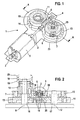
- Fig. 1 is a simple embodiment of an adjusting drive 1 for adjusting a window pane shown in a motor vehicle.
- a rotatably mounted output shaft 2 which is arranged between two spaced axial stops 3, 4.
- a gear screw 6 made of metal, in this embodiment made of brass.
- the gear screw 6 meshes with a first worm wheel 7 made of plastic, more precisely with a helical first engagement portion 8 of the first worm wheel 7.
- a second worm wheel 10 is arranged, which also meshes with a second, obliquely toothed engagement portion 11 with the worm gear 6.
- second axis of rotation 12 of the second worm wheel 10 is parallel to the first axis of rotation 9 of the first worm wheel 7 and is arranged at the same distance from the worm gear 6 as the first axis of rotation 9.
- Both axes of rotation 9, 12 are of an imaginary, not shown, the worm gear sixth cut in the transverse direction intersecting axis at right angles.
- the first, integrally formed worm wheel 7 adjacent to the first engagement portion 8 is provided with a first, straight toothed ring gear 13 which is in torque transmitting engagement with an identical second ring gear 14 of the second worm wheel 10.
- a first designed as a toothed element output member 15 is arranged, which serves for driving a window regulator mechanism, not shown, which is known per se.
- the reference numeral 23 is in Fig. 1 a possible circumferential contour of a Verstellantriebgephinuses indicated.
- the first worm wheel 7 is rotatably mounted on a first pin 16 and the second worm wheel 10 on a second pin 17.
- Fig. 2 are shown by different arrows the torque fluxes in different load conditions of the adjustment.
- the arrows marked with the reference numeral 18 show the torque flow in the normal adjustment state. It can be seen that a torque transmission takes place substantially only between the gear worm 6 and the first worm wheel 7.
- the arrows marked with the reference numeral 19 show the torque flow in the block stop, so when onset of tooth deformation of the first worm wheel 7. It can be seen that a torque transmission both between the worm gear 6 and the first worm wheel 7 and between the worm gear 6 and the second worm wheel 10th takes place, wherein the torque from the second worm wheel 10 and the second ring gear 14 to the first ring gear 13 and thus to the first worm wheel 7 and the output member 15 is passed.
- the arrows indicated by the reference numeral 20 show the torque flow at a load of the adjusting drive from the drive side during a so-called creep test. It can be seen that the arrows 20 are directed opposite to the arrows 19.
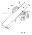
- FIG. 3 an alternative embodiment of an adjustment drive 1 is shown.
- the second worm wheel 10 in contrast to the second worm wheel 10 according to the embodiment described above, a second output element 21 which is identical to the first output element 15 of the first worm wheel 7 is formed.
- Both output elements 15, 21 are connected to a schematically indicated rack 22 in a torque-transmitting engagement.
- the torque flow is distributed in such a training already from the worm gear 6 on the two worm wheels 7, 10 and is transmitted via the output elements 15, 21 distributed on two opposite sides of the rack 22. With such a trained adjustment comparatively large torques can be transmitted.
- rectangular in cross-section rack and a rack with a round cross-section can be used.
Landscapes
- Gear Transmission (AREA)
- Gears, Cams (AREA)
- Power-Operated Mechanisms For Wings (AREA)
- Connection Of Motors, Electrical Generators, Mechanical Devices, And The Like (AREA)
Applications Claiming Priority (1)
| Application Number | Priority Date | Filing Date | Title |
|---|---|---|---|
| DE102007044350A DE102007044350A1 (de) | 2007-09-17 | 2007-09-17 | Verstellantrieb |
Publications (3)
| Publication Number | Publication Date |
|---|---|
| EP2037069A2 true EP2037069A2 (fr) | 2009-03-18 |
| EP2037069A3 EP2037069A3 (fr) | 2009-09-09 |
| EP2037069B1 EP2037069B1 (fr) | 2014-03-05 |
Family
ID=40184921
Family Applications (1)
| Application Number | Title | Priority Date | Filing Date |
|---|---|---|---|
| EP08104807.6A Not-in-force EP2037069B1 (fr) | 2007-09-17 | 2008-07-21 | Dispositif d'entraînement dans un voiture |
Country Status (3)
| Country | Link |
|---|---|
| US (1) | US20090071279A1 (fr) |
| EP (1) | EP2037069B1 (fr) |
| DE (1) | DE102007044350A1 (fr) |
Cited By (1)
| Publication number | Priority date | Publication date | Assignee | Title |
|---|---|---|---|---|
| CN114992284A (zh) * | 2022-05-18 | 2022-09-02 | 解明存 | 一种双蜗轮蜗杆减速机 |
Families Citing this family (13)
| Publication number | Priority date | Publication date | Assignee | Title |
|---|---|---|---|---|
| DE102005040547A1 (de) * | 2005-08-26 | 2007-03-01 | BSH Bosch und Siemens Hausgeräte GmbH | Elektromotorisches Küchengerät mit einem Bajonettverschluss für einen Elektromotor und eine Getriebestufe und Verfahren zum Montieren eines elektromotorischen Küchengeräts |
| CN102803789B (zh) | 2010-03-15 | 2015-11-25 | 马渊马达株式会社 | 涡轮、减速机以及带减速机的电机 |
| DE102013110349A1 (de) * | 2013-09-19 | 2015-03-19 | Hella Kgaa Hueck & Co. | Stellantrieb |
| KR101534943B1 (ko) * | 2013-11-20 | 2015-07-07 | 현대자동차주식회사 | 전자식 주차 브레이크 장치용 액츄에이터 |
| US10260566B2 (en) * | 2015-05-13 | 2019-04-16 | Mark H. Salerno | Marine antenna actuator |
| US10414384B2 (en) * | 2016-06-09 | 2019-09-17 | Lionel Smith, SR. | Portable semi-trailer landing-gear motor system and method |
| CN107355513B (zh) * | 2017-07-06 | 2023-08-15 | 上海中鹏岳博实业发展有限公司 | 传动结构及后视镜驱动器 |
| DE202017106875U1 (de) * | 2017-11-13 | 2019-02-14 | Dewertokin Gmbh | Elektromotorischer Linearantrieb |
| CN109854713B (zh) * | 2017-11-30 | 2022-06-10 | 日本电产株式会社 | 齿轮单元、齿轮箱、齿轮马达及包含齿轮马达的电气产品 |
| DE102018211443A1 (de) * | 2018-07-10 | 2020-01-16 | Robert Bosch Gmbh | Druckerzeugungsvorrichtung für ein Bremssystem eines Fahrzeugs |
| CN109538698A (zh) * | 2018-12-25 | 2019-03-29 | 德恩科电机(太仓)有限公司 | 一种低噪音蜗轮蜗杆减速箱 |
| CN109780139A (zh) * | 2019-03-20 | 2019-05-21 | 佛山市威王日用电器有限公司 | 一种双向蜗轮传动装置 |
| CN115556815B (zh) * | 2022-09-27 | 2026-01-30 | 浙江凌昇动力科技有限公司 | 方向盘的调节机构及车辆 |
Family Cites Families (14)
| Publication number | Priority date | Publication date | Assignee | Title |
|---|---|---|---|---|
| US219706A (en) * | 1879-09-16 | Improvement in horse-powers | ||
| US790875A (en) * | 1905-02-04 | 1905-05-30 | Daniel Abrey | Hoisting and power-transmitting machine. |
| US1338377A (en) * | 1920-02-19 | 1920-04-27 | John C Kopf | Mechanical movement |
| US3381539A (en) * | 1965-10-21 | 1968-05-07 | Herbert C. Ovshinsky | Linear actuator |
| US3706236A (en) * | 1970-11-12 | 1972-12-19 | Ferro Mfg Corp | Tailgate window regulator |
| JPS59169450U (ja) * | 1983-04-28 | 1984-11-13 | 自動車電機工業株式会社 | 自動車用モ−タの減速装置 |
| FR2546252B1 (fr) * | 1983-05-16 | 1988-01-15 | Guichard Roland | Transmission a engrenage comportant deux vis sans fin |
| US5363713A (en) * | 1993-04-29 | 1994-11-15 | Eaton Corporation | Quieted servoactuator |
| US5749937A (en) * | 1995-03-14 | 1998-05-12 | Lockheed Idaho Technologies Company | Fast quench reactor and method |
| US6216394B1 (en) * | 1998-09-21 | 2001-04-17 | Paul J. Fenelon | Window lift mechanism |
| DE10128414A1 (de) * | 2001-06-12 | 2002-12-19 | Daimler Chrysler Ag | Abgasreinigungsanlage mit Reduktionsmittelversorgung |
| US7082753B2 (en) * | 2001-12-03 | 2006-08-01 | Catalytica Energy Systems, Inc. | System and methods for improved emission control of internal combustion engines using pulsed fuel flow |
| DE10207986A1 (de) * | 2002-02-25 | 2003-09-04 | Daimler Chrysler Ag | Abgasreinigungsanlage für eine Brennkraftmaschine |
| DE10237777A1 (de) * | 2002-08-17 | 2004-02-26 | Daimlerchrysler Ag | Brennkraftmaschine mit Reduktionsmittelerzeugungseinheit und Betriebsverfahren hierfür |
-
2007
- 2007-09-17 DE DE102007044350A patent/DE102007044350A1/de not_active Withdrawn
-
2008
- 2008-07-21 EP EP08104807.6A patent/EP2037069B1/fr not_active Not-in-force
- 2008-09-16 US US12/211,590 patent/US20090071279A1/en not_active Abandoned
Cited By (1)
| Publication number | Priority date | Publication date | Assignee | Title |
|---|---|---|---|---|
| CN114992284A (zh) * | 2022-05-18 | 2022-09-02 | 解明存 | 一种双蜗轮蜗杆减速机 |
Also Published As
| Publication number | Publication date |
|---|---|
| DE102007044350A1 (de) | 2009-03-19 |
| US20090071279A1 (en) | 2009-03-19 |
| EP2037069B1 (fr) | 2014-03-05 |
| EP2037069A3 (fr) | 2009-09-09 |
Similar Documents
| Publication | Publication Date | Title |
|---|---|---|
| EP2037069B1 (fr) | Dispositif d'entraînement dans un voiture | |
| DE69706579T2 (de) | Motorgetriebe zum Antrieb des Armes eines Kraftfahrzeugscheibenwischers | |
| EP2730807B1 (fr) | Engrenage épicycloïdal avec plusieurs étages de démultiplication | |
| DE4210302C2 (de) | Getriebemotor, insbesondere elektromotorischer Fensterantrieb oder Schiebedachantrieb | |
| EP3358218A2 (fr) | Dispositif de réglage destiné au réglage d'un siège de véhicule le long d'un axe de déplacement | |
| WO2019086068A1 (fr) | Mécanisme de réglage pour des applications dans le domaine des véhicules à moteur | |
| DE102017205721B4 (de) | Getriebeeinheit für ein Kraftfahrzeug | |
| EP1989096A1 (fr) | Engrenage hélicoïdal pour une direction à crémaillère | |
| DE102006042322A1 (de) | Scheibenwischeranlage mit einem Scheibenwischerantrieb, insbesondere für einen Heckscheibenwischer eines Kraftfahrzeugs mit einer modular austauschbaren Getriebeanordnung | |
| EP2519759B1 (fr) | Entraînement de réglage possédant des fonctions supplémentaires intégrées | |
| DE19861276B4 (de) | Spindel- oder Schneckenantrieb für Verstelleinrichtungen in Kraftfahrzeugen | |
| EP2536600A1 (fr) | Unité d'entraînement pour système d'essuie-glace | |
| DE102014104288A1 (de) | Zahnrad | |
| EP1134453A2 (fr) | Actionneur pour partie réglable d'un véhicule | |
| DE102019220165A1 (de) | Antriebseinrichtung und Komfortantrieb mit einer Antriebseinrichtung | |
| DE19861278B4 (de) | Spindel- oder Schneckenantrieb für Verstelleinrichtungen in Kraftfahrzeugen | |
| DE102014207992A1 (de) | Verfahren zur Montage einer Getriebe-Antriebseinheit, Zentrierelement zum Durchführen des Verfahrens und Getriebe-Antriebseinheit | |
| DE2446839B2 (de) | Vorrichtung, insbesondere zum Antrieb einer Wischerwelle von Wischvorrichtungen an Kraftfahrzeugen | |
| DE102024107399B3 (de) | Antrieb für eine Tür oder ein Fenster mit verbessertem Wirkungsgrad | |
| EP1811123A2 (fr) | Bloc moteur tubulaire | |
| DE10240552A1 (de) | Kraftfahrzeug Türschloß | |
| WO2005061832A2 (fr) | Systeme leve-vitre avec dispositif d'entrainement pouvant fonctionner au choix de facon manuelle ou motorisee | |
| DE102020134307B4 (de) | Getriebe und vorrichtung zum antreiben einer fahrzeugkomponente | |
| DE102010064085A1 (de) | Getriebe-Antriebseinheit, Funktionselement sowie eine aus einer Getriebe-Antriebseinheit und einem Funktionselement bestehende Anordnung | |
| EP1636515B1 (fr) | Moteur electrique con u pour une boite de vitesses automatique |
Legal Events
| Date | Code | Title | Description |
|---|---|---|---|
| PUAI | Public reference made under article 153(3) epc to a published international application that has entered the european phase |
Free format text: ORIGINAL CODE: 0009012 |
|
| AK | Designated contracting states |
Kind code of ref document: A2 Designated state(s): AT BE BG CH CY CZ DE DK EE ES FI FR GB GR HR HU IE IS IT LI LT LU LV MC MT NL NO PL PT RO SE SI SK TR |
|
| AX | Request for extension of the european patent |
Extension state: AL BA MK RS |
|
| PUAL | Search report despatched |
Free format text: ORIGINAL CODE: 0009013 |
|
| AK | Designated contracting states |
Kind code of ref document: A3 Designated state(s): AT BE BG CH CY CZ DE DK EE ES FI FR GB GR HR HU IE IS IT LI LT LU LV MC MT NL NO PL PT RO SE SI SK TR |
|
| AX | Request for extension of the european patent |
Extension state: AL BA MK RS |
|
| 17P | Request for examination filed |
Effective date: 20100309 |
|
| 17Q | First examination report despatched |
Effective date: 20100401 |
|
| AKX | Designation fees paid |
Designated state(s): DE ES FR IT |
|
| GRAP | Despatch of communication of intention to grant a patent |
Free format text: ORIGINAL CODE: EPIDOSNIGR1 |
|
| GRAJ | Information related to disapproval of communication of intention to grant by the applicant or resumption of examination proceedings by the epo deleted |
Free format text: ORIGINAL CODE: EPIDOSDIGR1 |
|
| GRAP | Despatch of communication of intention to grant a patent |
Free format text: ORIGINAL CODE: EPIDOSNIGR1 |
|
| INTG | Intention to grant announced |
Effective date: 20131205 |
|
| INTG | Intention to grant announced |
Effective date: 20131216 |
|
| GRAS | Grant fee paid |
Free format text: ORIGINAL CODE: EPIDOSNIGR3 |
|
| GRAA | (expected) grant |
Free format text: ORIGINAL CODE: 0009210 |
|
| AK | Designated contracting states |
Kind code of ref document: B1 Designated state(s): DE ES FR IT |
|
| REG | Reference to a national code |
Ref country code: DE Ref legal event code: R096 Ref document number: 502008011396 Country of ref document: DE Effective date: 20140417 |
|
| PG25 | Lapsed in a contracting state [announced via postgrant information from national office to epo] |
Ref country code: ES Free format text: LAPSE BECAUSE OF FAILURE TO SUBMIT A TRANSLATION OF THE DESCRIPTION OR TO PAY THE FEE WITHIN THE PRESCRIBED TIME-LIMIT Effective date: 20140305 |
|
| REG | Reference to a national code |
Ref country code: DE Ref legal event code: R097 Ref document number: 502008011396 Country of ref document: DE |
|
| PLBE | No opposition filed within time limit |
Free format text: ORIGINAL CODE: 0009261 |
|
| STAA | Information on the status of an ep patent application or granted ep patent |
Free format text: STATUS: NO OPPOSITION FILED WITHIN TIME LIMIT |
|
| 26N | No opposition filed |
Effective date: 20141208 |
|
| REG | Reference to a national code |
Ref country code: DE Ref legal event code: R097 Ref document number: 502008011396 Country of ref document: DE Effective date: 20141208 |
|
| PG25 | Lapsed in a contracting state [announced via postgrant information from national office to epo] |
Ref country code: IT Free format text: LAPSE BECAUSE OF FAILURE TO SUBMIT A TRANSLATION OF THE DESCRIPTION OR TO PAY THE FEE WITHIN THE PRESCRIBED TIME-LIMIT Effective date: 20140305 |
|
| REG | Reference to a national code |
Ref country code: FR Ref legal event code: ST Effective date: 20150331 |
|
| PG25 | Lapsed in a contracting state [announced via postgrant information from national office to epo] |
Ref country code: FR Free format text: LAPSE BECAUSE OF NON-PAYMENT OF DUE FEES Effective date: 20140731 |
|
| PGFP | Annual fee paid to national office [announced via postgrant information from national office to epo] |
Ref country code: DE Payment date: 20180928 Year of fee payment: 11 |
|
| REG | Reference to a national code |
Ref country code: DE Ref legal event code: R119 Ref document number: 502008011396 Country of ref document: DE |
|
| PG25 | Lapsed in a contracting state [announced via postgrant information from national office to epo] |
Ref country code: DE Free format text: LAPSE BECAUSE OF NON-PAYMENT OF DUE FEES Effective date: 20200201 |