EP3358218A2 - Dispositif de réglage destiné au réglage d'un siège de véhicule le long d'un axe de déplacement - Google Patents
Dispositif de réglage destiné au réglage d'un siège de véhicule le long d'un axe de déplacement Download PDFInfo
- Publication number
- EP3358218A2 EP3358218A2 EP18153616.0A EP18153616A EP3358218A2 EP 3358218 A2 EP3358218 A2 EP 3358218A2 EP 18153616 A EP18153616 A EP 18153616A EP 3358218 A2 EP3358218 A2 EP 3358218A2
- Authority
- EP
- European Patent Office
- Prior art keywords
- gear
- drive
- threaded spindle
- cavity
- upper rail
- Prior art date
- Legal status (The legal status is an assumption and is not a legal conclusion. Google has not performed a legal analysis and makes no representation as to the accuracy of the status listed.)
- Withdrawn
Links
- 230000005540 biological transmission Effects 0.000 claims abstract description 47
- 238000006073 displacement reaction Methods 0.000 claims abstract description 40
- 125000006850 spacer group Chemical group 0.000 claims 1
- 238000013519 translation Methods 0.000 description 4
- 230000014616 translation Effects 0.000 description 4
- 238000011161 development Methods 0.000 description 2
- 230000008092 positive effect Effects 0.000 description 2
- 238000012546 transfer Methods 0.000 description 2
- 230000006978 adaptation Effects 0.000 description 1
- 238000013459 approach Methods 0.000 description 1
- 230000001419 dependent effect Effects 0.000 description 1
- 238000013461 design Methods 0.000 description 1
- 238000009434 installation Methods 0.000 description 1
- 238000004519 manufacturing process Methods 0.000 description 1
- 230000008447 perception Effects 0.000 description 1
Images

Classifications
-
- B—PERFORMING OPERATIONS; TRANSPORTING
- B60—VEHICLES IN GENERAL
- B60N—SEATS SPECIALLY ADAPTED FOR VEHICLES; VEHICLE PASSENGER ACCOMMODATION NOT OTHERWISE PROVIDED FOR
- B60N2/00—Seats specially adapted for vehicles; Arrangement or mounting of seats in vehicles
- B60N2/02—Seats specially adapted for vehicles; Arrangement or mounting of seats in vehicles the seat or part thereof being movable, e.g. adjustable
- B60N2/0224—Non-manual adjustments, e.g. with electrical operation
- B60N2/02246—Electric motors therefor
-
- B—PERFORMING OPERATIONS; TRANSPORTING
- B60—VEHICLES IN GENERAL
- B60N—SEATS SPECIALLY ADAPTED FOR VEHICLES; VEHICLE PASSENGER ACCOMMODATION NOT OTHERWISE PROVIDED FOR
- B60N2/00—Seats specially adapted for vehicles; Arrangement or mounting of seats in vehicles
- B60N2/02—Seats specially adapted for vehicles; Arrangement or mounting of seats in vehicles the seat or part thereof being movable, e.g. adjustable
- B60N2/04—Seats specially adapted for vehicles; Arrangement or mounting of seats in vehicles the seat or part thereof being movable, e.g. adjustable the whole seat being movable
- B60N2/06—Seats specially adapted for vehicles; Arrangement or mounting of seats in vehicles the seat or part thereof being movable, e.g. adjustable the whole seat being movable slidable
- B60N2/067—Seats specially adapted for vehicles; Arrangement or mounting of seats in vehicles the seat or part thereof being movable, e.g. adjustable the whole seat being movable slidable by linear actuators, e.g. linear screw mechanisms
-
- B—PERFORMING OPERATIONS; TRANSPORTING
- B60—VEHICLES IN GENERAL
- B60N—SEATS SPECIALLY ADAPTED FOR VEHICLES; VEHICLE PASSENGER ACCOMMODATION NOT OTHERWISE PROVIDED FOR
- B60N2/00—Seats specially adapted for vehicles; Arrangement or mounting of seats in vehicles
- B60N2/02—Seats specially adapted for vehicles; Arrangement or mounting of seats in vehicles the seat or part thereof being movable, e.g. adjustable
- B60N2/0224—Non-manual adjustments, e.g. with electrical operation
- B60N2/02246—Electric motors therefor
- B60N2/02253—Electric motors therefor characterised by the transmission between the electric motor and the seat or seat parts
-
- B—PERFORMING OPERATIONS; TRANSPORTING
- B60—VEHICLES IN GENERAL
- B60N—SEATS SPECIALLY ADAPTED FOR VEHICLES; VEHICLE PASSENGER ACCOMMODATION NOT OTHERWISE PROVIDED FOR
- B60N2/00—Seats specially adapted for vehicles; Arrangement or mounting of seats in vehicles
- B60N2/02—Seats specially adapted for vehicles; Arrangement or mounting of seats in vehicles the seat or part thereof being movable, e.g. adjustable
- B60N2/0224—Non-manual adjustments, e.g. with electrical operation
- B60N2/02246—Electric motors therefor
- B60N2/02258—Electric motors therefor characterised by the mounting of the electric motor for adjusting the seat
-
- B—PERFORMING OPERATIONS; TRANSPORTING
- B60—VEHICLES IN GENERAL
- B60N—SEATS SPECIALLY ADAPTED FOR VEHICLES; VEHICLE PASSENGER ACCOMMODATION NOT OTHERWISE PROVIDED FOR
- B60N2/00—Seats specially adapted for vehicles; Arrangement or mounting of seats in vehicles
- B60N2/02—Seats specially adapted for vehicles; Arrangement or mounting of seats in vehicles the seat or part thereof being movable, e.g. adjustable
- B60N2/04—Seats specially adapted for vehicles; Arrangement or mounting of seats in vehicles the seat or part thereof being movable, e.g. adjustable the whole seat being movable
- B60N2/16—Seats specially adapted for vehicles; Arrangement or mounting of seats in vehicles the seat or part thereof being movable, e.g. adjustable the whole seat being movable height-adjustable
- B60N2/18—Seats specially adapted for vehicles; Arrangement or mounting of seats in vehicles the seat or part thereof being movable, e.g. adjustable the whole seat being movable height-adjustable the front or the rear portion of the seat being adjustable, e.g. independently of each other
- B60N2/185—Seats specially adapted for vehicles; Arrangement or mounting of seats in vehicles the seat or part thereof being movable, e.g. adjustable the whole seat being movable height-adjustable the front or the rear portion of the seat being adjustable, e.g. independently of each other characterised by the drive mechanism
- B60N2/1853—Linear actuator, e.g. screw mechanism
-
- B—PERFORMING OPERATIONS; TRANSPORTING
- B60—VEHICLES IN GENERAL
- B60N—SEATS SPECIALLY ADAPTED FOR VEHICLES; VEHICLE PASSENGER ACCOMMODATION NOT OTHERWISE PROVIDED FOR
- B60N2/00—Seats specially adapted for vehicles; Arrangement or mounting of seats in vehicles
- B60N2/02—Seats specially adapted for vehicles; Arrangement or mounting of seats in vehicles the seat or part thereof being movable, e.g. adjustable
- B60N2/04—Seats specially adapted for vehicles; Arrangement or mounting of seats in vehicles the seat or part thereof being movable, e.g. adjustable the whole seat being movable
- B60N2/16—Seats specially adapted for vehicles; Arrangement or mounting of seats in vehicles the seat or part thereof being movable, e.g. adjustable the whole seat being movable height-adjustable
- B60N2/18—Seats specially adapted for vehicles; Arrangement or mounting of seats in vehicles the seat or part thereof being movable, e.g. adjustable the whole seat being movable height-adjustable the front or the rear portion of the seat being adjustable, e.g. independently of each other
- B60N2/185—Seats specially adapted for vehicles; Arrangement or mounting of seats in vehicles the seat or part thereof being movable, e.g. adjustable the whole seat being movable height-adjustable the front or the rear portion of the seat being adjustable, e.g. independently of each other characterised by the drive mechanism
- B60N2/1867—Cycloidal or planetary mechanism
-
- B—PERFORMING OPERATIONS; TRANSPORTING
- B60—VEHICLES IN GENERAL
- B60N—SEATS SPECIALLY ADAPTED FOR VEHICLES; VEHICLE PASSENGER ACCOMMODATION NOT OTHERWISE PROVIDED FOR
- B60N2/00—Seats specially adapted for vehicles; Arrangement or mounting of seats in vehicles
- B60N2/02—Seats specially adapted for vehicles; Arrangement or mounting of seats in vehicles the seat or part thereof being movable, e.g. adjustable
- B60N2/04—Seats specially adapted for vehicles; Arrangement or mounting of seats in vehicles the seat or part thereof being movable, e.g. adjustable the whole seat being movable
- B60N2/16—Seats specially adapted for vehicles; Arrangement or mounting of seats in vehicles the seat or part thereof being movable, e.g. adjustable the whole seat being movable height-adjustable
- B60N2/18—Seats specially adapted for vehicles; Arrangement or mounting of seats in vehicles the seat or part thereof being movable, e.g. adjustable the whole seat being movable height-adjustable the front or the rear portion of the seat being adjustable, e.g. independently of each other
- B60N2/185—Seats specially adapted for vehicles; Arrangement or mounting of seats in vehicles the seat or part thereof being movable, e.g. adjustable the whole seat being movable height-adjustable the front or the rear portion of the seat being adjustable, e.g. independently of each other characterised by the drive mechanism
- B60N2/1871—Worm and worm gear articulations
-
- F—MECHANICAL ENGINEERING; LIGHTING; HEATING; WEAPONS; BLASTING
- F16—ENGINEERING ELEMENTS AND UNITS; GENERAL MEASURES FOR PRODUCING AND MAINTAINING EFFECTIVE FUNCTIONING OF MACHINES OR INSTALLATIONS; THERMAL INSULATION IN GENERAL
- F16H—GEARING
- F16H1/00—Toothed gearings for conveying rotary motion
- F16H1/28—Toothed gearings for conveying rotary motion with gears having orbital motion
- F16H1/30—Toothed gearings for conveying rotary motion with gears having orbital motion in which an orbital gear has an axis crossing the main axis of the gearing and has helical teeth or is a worm
-
- B—PERFORMING OPERATIONS; TRANSPORTING
- B60—VEHICLES IN GENERAL
- B60N—SEATS SPECIALLY ADAPTED FOR VEHICLES; VEHICLE PASSENGER ACCOMMODATION NOT OTHERWISE PROVIDED FOR
- B60N2205/00—General mechanical or structural details
- B60N2205/20—Measures for elimination or compensation of play or backlash
-
- F—MECHANICAL ENGINEERING; LIGHTING; HEATING; WEAPONS; BLASTING
- F16—ENGINEERING ELEMENTS AND UNITS; GENERAL MEASURES FOR PRODUCING AND MAINTAINING EFFECTIVE FUNCTIONING OF MACHINES OR INSTALLATIONS; THERMAL INSULATION IN GENERAL
- F16H—GEARING
- F16H25/00—Gearings comprising primarily only cams, cam-followers and screw-and-nut mechanisms
- F16H25/18—Gearings comprising primarily only cams, cam-followers and screw-and-nut mechanisms for conveying or interconverting oscillating or reciprocating motions
- F16H25/20—Screw mechanisms
- F16H2025/2062—Arrangements for driving the actuator
- F16H2025/2087—Arrangements for driving the actuator using planetary gears
Definitions
- the present invention relates to an adjusting device for adjusting a vehicle seat of a vehicle along a displacement axis.
- FIG. 1 is an adjustment known from the prior art for Weglksverstellen a vehicle seat along a displacement axis shown in perspective, wherein the displacement axis coincides approximately with the longitudinal axis of the vehicle.
- Such adjusting device is for example in the DE 10 2006 011 718 A1 describe.
- the adjusting device has a first lower rail fixedly connected to the vehicle and a second lower rail fixedly connected to the vehicle, wherein FIG. 1 only the first lower rail is shown.
- the lower rails may be fixed to the floor of the vehicle interior.
- the adjusting device has a parallel in the first lower rail to the displacement axis slidably mounted first upper rail and slidably mounted in the second lower rail parallel to the displacement axis second upper rail on, again only the first upper rail is shown.
- first lower rail and the first upper rail surround a first cavity and the second lower rail and the second upper rail a second cavity.
- a first threaded spindle is arranged, which is rotatably connected using brackets with the first lower rail.
- a second threaded spindle is arranged in the second cavity and rotatably connected to the second lower rail.
- the adjusting device cooperates with the first threaded spindle and at least partially disposed in the first cavity and fixedly connected to the first upper rail first gear and cooperating with the second threaded spindle and at least partially disposed in the second cavity and fixedly connected to the second upper rail second transmission ,
- a carrier which is attached to the first and second upper rail.
- a drive motor is attached, which is usually designed as an electric motor.
- a drive train which comprises a first drive shaft and a second drive shaft which extend substantially linearly.
- FIG. 2A the adjusting device is illustrated by a basic plan view.
- the gear is designed as a worm gear, which comprises a worm and a worm gear designed as a spindle nut, which mesh with one another in meshing engagement.
- the worm gear is based on a basic representation in FIG. 2B shown separately.
- the spindle nut has an internal thread, not shown, into which the threaded spindle is screwed.
- the drive shafts are rotatably connected to the screws.
- the adjusting device is operated in the following manner: By actuating the drive motor, the two drive shafts are rotated. The rotation of the drive shafts is transmitted to the screws, which in turn rotates the spindle nuts. Due to this rotation, the spindle nuts move along the threaded spindle. Since the gears are firmly connected to the top rails, they move along with the top rails along the displacement axis within the bottom rails. The carrier, the drive train, the drive motor and the vehicle seat not shown follow this movement.
- the length of the maximum displacement of the vehicle seat along the displacement axis substantially equal to the length of the threaded spindles.
- the case swept by the carrier and the drive train surface is in FIG. 2a approximated by a hatched section.
- no obstacle may be arranged on the marked surface between the two lower rails against which the drive train, the carrier and / or the drive motor can abut.
- the space on the marked area between the lower rails lends itself to the arrangement of flat components of all kinds such as fire extinguishers, subwoofers, batteries or other electronic components in particular for the following reason: Since this space is overbuilt at least for the most part of the vehicle seat, this room can not be used as a footwell, so that the arrangement of flat objects would not interfere and these can not be charged or damaged by the occupants. However, since this space must remain free for ensuring the adjustability of the vehicle seat over the entire adjustment for the reasons explained above, this space can not be used for the arrangement of components.
- Object of the present invention is therefore to further develop an adjusting device for adjusting a vehicle seat of a vehicle along a displacement axis of the type mentioned in such a way that the space between the lower rails of the adjusting device for arranging components is at least partially usable.
- One embodiment of the invention relates to an adjusting device for adjusting a vehicle seat of a vehicle along a displacement axis, comprising a first lower rail fixedly connected to the vehicle and a second lower rail fixedly connected to the vehicle, and a first upper rail and slidably mounted in the first lower rail parallel to the displacement axis a second upper rail mounted displaceably in the second lower rail parallel to the displacement axis, the first lower rail and the first upper rail enclosing a first cavity and the second lower rail and the second upper rail enclosing a second cavity.
- this embodiment of the adjusting device comprises a arranged in the first cavity and rotatably connected to the first lower rail first threaded spindle and arranged in the second cavity and rotatably connected to the second lower rail second threaded spindle, cooperating with the first threaded spindle and at least partially disposed in the first cavity and fixedly connected to the first upper rail first gear and cooperating with the second threaded spindle and at least partially disposed in the second cavity and fixedly connected to the second upper rail second gear, arranged between the first upper rail and the second upper rail drive motor, and one between the drive motor and the first transmission and between the drive motor and the second transmission extending drive train, wherein the drive motor relative to the displacement axis offset by a distance to the first gear and the second Transmission is arranged and the drive train comprises distance bridging means for bridging the distance.
- the transmission, the drive train and the drive motor are arranged approximately centrally on the upper rail.
- the use of the proposed distance bridging means in the drive train makes it possible to arrange the drive motor and the drive train offset by a selectable distance with respect to the displacement axis, for example in the region of the front or rear ends of the top rails.
- the drive motor and drive train are only partially displaced into the space between the lower rails while being displaced out of the space between the lower rails upon adjustment in the opposite direction. A portion of the space between the lower rails is not swept due to the proposed embodiment of the adjustment of the drive train and the drive motor. In this part of the room components can be arranged so that it can be used.
- the distance bridging means comprises a flexible first drive shaft and a flexible second drive shaft.
- Flexible drive shafts also called flex shafts, make it possible in a simple manner to overcome the distance between the drive motor and the transmissions, without the need for additional design measures.
- the first gear and the second gear can each be designed as a worm gear.
- Worm gears enable high gear ratios in a relatively small space.
- they are characterized by a low noise, which has a positive effect on the perception of the seat adjustment by the vehicle occupants.
- the worm gear may comprise a worm with a worm axis and a worm wheel with a worm wheel axis, wherein the worm axis and the worm wheel axis include an axis angle which is less than 90 °.
- the worm axis and the worm wheel axis enclose an axis angle of 90 °, but with an appropriate adaptation of the teeth of the worm wheel and the worm also axial angles of less than 90 ° can be represented.
- Such axial angles are particularly suitable in conjunction with flexible drive shafts, as this allows the angle difference, which must bridge the flexible drive shafts, can be kept low.
- the flexible drive shafts are correspondingly less bent and therefore less stressed, which can increase the life and reduce the probability of failure.
- the acoustics are improved.
- a further developed embodiment is characterized in that the first gear and the second gear are each formed as a spur gear.
- Helical gear are characterized by a high efficiency, so that the adjusting device can be operated particularly efficiently according to this embodiment.
- a further embodiment is characterized in that the distance bridging means comprise a first belt transmission and a second belt transmission. Compared to spur gears belt transmissions can be designed so that they have a reduced noise.
- the distance bridging means may comprise a flexible first drive shaft and a flexible second drive shaft.
- the first belt drive on the drive side have a first drive shaft connected to the first drive wheel and the output side a first output gear, which is designed as a cooperating with the first threaded spindle first spindle nut.
- the second belt drive may have a second drive wheel connected to the second drive shaft and a second output drive on the output side, which is designed as a second spindle nut cooperating with the second threaded spindle.
- this embodiment can be adapted to the different structural conditions of the existing adjusting devices.
- the connection of the drive wheel to the flexible drive shaft can be simplified in comparison to spur gear transmissions.
- the drive train, the first and the second gear and the first and the second threaded spindle are formed so that between the torque provided by the drive motor and the torque applied to the threaded spindles a total gear ratio between 6 and 7 is applied, the first and the second threaded spindle has a thread pitch which is reduced or increased in relation to a thread normal pitch, and the drive train and / or the first and the second gear are adapted to the reduced or increased thread pitch, that the overall translation ratio is maintained.
- the thread normal pitch between 2.5 and 3.5 mm. Compared to this thread normal pitch, the thread pitch is reduced for example by 60 to 70%.
- the drive train and / or the transmission are adapted accordingly. If the drivetrain remains unchanged, the transmission must reduce the output speed from the drive motor less so that the gear ratio of the transmission in comparison to known adjusting closer to 1. This measure can be used purposefully especially for spur gears, since in spur gears without intermediate wheels, the distance of the axes of the two spur gears is determined by their diameters. Depending on the structural conditions, the distance but must have a certain minimum, for example, to connect the flexible drive shaft with the spur gear can. The changed thread pitch can be changed accordingly to match the diameter of the two spur gears and thus to increase or decrease the center distance.
- the drive train, the first and the second gear and the first and the second threaded spindle are formed so that between the torque provided by the drive motor and the voltage applied to the threaded spindles a total gear ratio between 6 and 7 is applied, the drive train another Transmission, in particular a motor worm gear comprises, and the first and the second threaded spindle and / or the first and the second gear so to the other transmission are adjusted so that the overall translation ratio is maintained.
- the other transmission and in particular the motor worm gear, which is a transfer case, is used to reduce the rotational speeds of the flexible drive shafts and in the transmissions connected to them, thereby reducing high heat development and reducing associated wear. Furthermore, a lower speed in the gearboxes connected to the drive shafts has a positive effect on the noise development.
- the drive train comprises a first drive shaft and a second drive shaft, wherein the first gear is formed as a first worm gear and the second gear as a second worm gear, the first belt drive on the drive side connected to the first drive shaft first drive wheel and the output side with a the first worm gear cooperating first output gear and the second belt drive on the drive side comprise a second drive shaft connected to the second drive shaft and the output side cooperating with the second worm gear second output gear.
- linearly extending drive shafts and worm gears can be used, which is also the case with known adjusting devices.
- the worm gears already used for known adjusting devices can be used without structural changes. In this respect, the structural adjustment is essentially limited to the provision of the belt transmission, so that the additional effort compared to the known adjusting devices is low.
- One embodiment of the invention relates to an adjusting device for adjusting a vehicle seat of a vehicle along a displacement axis, comprising a first lower rail fixedly connected to the vehicle and a second lower rail fixedly connected to the vehicle, and a first upper rail and slidably mounted in the first lower rail parallel to the displacement axis a second upper rail mounted displaceably in the second lower rail parallel to the displacement axis, the first lower rail and the first upper rail enclosing a first cavity and the second lower rail and the second upper rail enclosing a second cavity.
- this embodiment of the adjustment device comprises a first screw arranged in the first cavity and rotatably mounted about a first axis of rotation and a second cavity and rotatably mounted about a second axis of rotation second threaded spindle, cooperating with the first threaded spindle and at least partially disposed in the first cavity and fixedly connected to the first upper rail first spindle nut and cooperating with the second threaded spindle and at least partially disposed in the second cavity and fixedly connected to the second upper rail second spindle nut.
- this embodiment of the adjusting device has a first drive motor, which is operatively connected to drive the first threaded spindle on the output side with the first threaded spindle, and a second drive motor, which is operatively connected to drive the second threaded spindle with the second threaded spindle.
- the threaded spindles are rotatable in the cavity between the top rails and the lower rails stored.
- Each threaded spindle is assigned its own drive motor in order to set the threaded spindles in rotation.
- the respective drive motor can be arranged very close to the relevant threaded spindle, so that the space taken is kept low.
- no drive motor is arranged between the top rails and no drive train is present, which runs through the space between the two top rails. The space between the two lower rails is fully usable.
- the first drive motor may comprise a first output shaft and the second drive motor may comprise a second output shaft and the first output shaft may be aligned with the first axis of rotation and the second output shaft may be aligned with the second axis of rotation.
- the output shafts can be rigid and therefore simple in comparison to flexible shafts, which reduces the manufacturing cost.
- the space occupied by the two drive motors between the two sub-rails is kept low, so that this space is completely or almost completely usable.
- the Verstellvorrihctung comprises a first gear, which is operatively connected to the first drive motor for driving the first threaded spindle and the output side with the first threaded spindle, and a second transmission, which drive side with the second drive motor for driving the second threaded spindle and the output side the second threaded spindle is operatively connected.
- the use of gears makes it possible to provide the necessary torque for adjusting the vehicle seat, without the drive motor accordingly must be large, so that in particular space can be saved.
- the drive motors used to adjust the vehicle seat are almost without exception electric motors that deliver a comparatively high speed.
- the vehicle seat should, however, preferably be adjusted at a low speed, which can be achieved with the use of transmissions in a simple and space-saving manner.
- first gear can be configured as a first planetary gear and the second gear as a second planetary gear.
- Planetary gears provide a high gear ratio within a small space.
- both the planetary gear and the drive motor can be arranged on the same axis as the threaded spindle, which saves installation space.
- the first planetary gear and / or the second planetary gear may be formed as a helical gear planetary gear.
- Worm gear planetary gears offer an even higher gear ratio compared to conventional planetary gears with otherwise identical boundary conditions.
- the engagement within the helical gear planetary gear is very uniform and the noise compared to conventional planetary gears lower.
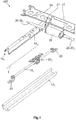
- FIG. 1 is a known adjustment 10P for WeglNicolsverstellen a vehicle seat, not shown, along a displacement axis L shown in perspective, wherein the displacement axis L coincides approximately with the longitudinal axis of the vehicle, also not shown.
- the adjusting device 10P has a first bottom rail 12 1 fixedly connected to the vehicle and a second bottom rail 12 2 fixedly connected to the vehicle, wherein FIG. 1 only the first bottom rail 12 1 is shown.
- the lower rails 12 1 , 12 2 may be fixed to the floor of the vehicle interior.
- the adjusting device 10P has a first upper rail 14 1 mounted displaceably in the first lower rail 12 1 parallel to the displacement axis L and a second upper rail 14 2 mounted displaceably in the second lower rail 12 2 parallel to the displacement axis L, again only the first upper rail 14 1 is shown.
- the top rails 14 1 , 14 2 slide directly or not shown adjusting and / or bearing elements on the bottom rails 12 1 , 12 second At the two upper rails 14 1 , 14 2 an unillustrated vehicle seat is attached.
- first bottom rail 12 1 and the first top rail 14 1 enclose a first cavity 16 1 and the second bottom rail 12 2 and the second top rail 14 2 surround a second cavity 16 2 .
- first threaded spindle 18 1 is arranged, which is rotatably connected to the first lower rail 12 1 using brackets 20.
- second threaded spindle 18 2 arranged and rotatably connected to the second lower rail 12 2 (not shown).
- the adjusting device 10P cooperates with the first threaded spindle 18 1 and at least partially disposed in the first cavity 16 1 and fixedly connected to the first upper rail 14 1 first transmission 22 1 and cooperating with the second threaded spindle 18 2 and at least partially in the second cavity 16 2 arranged and fixed to the second upper rail 14 2 connected second gear 22 2 on.
- a carrier 24 which is fixed to the first and second upper rail 14 1 , 14 2 .
- a drive motor 26 is attached with fastening tabs 27, which is usually designed as an electric motor.
- the provision of the carrier 24 is not absolutely necessary. Instead of the carrier 24, the drive motor 26 may also be attached to the vehicle seat.
- a drive train 28 which comprises a linearly extending first drive shaft 30 1 and a linearly extending second drive shaft 30 2 .
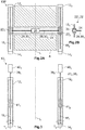
- FIG. 2A the adjusting device 10 is illustrated by a basic plan view.
- the gearbox 22 1 , 22 2 are executed in the illustrated example each as a worm gear 32 which comprises a worm 34 and a worm gear 36 designed as a spindle nut 41, which are in meshing engagement with each other.
- the worm gear 32 is based on a schematic representation in FIG. 2B shown separately.
- the spindle nut 41 has an internal thread, not shown, into which the threaded spindle 18 1 is screwed.
- the drive shafts 30 are rotatably connected to the screws 34.
- the adjusting device 10P is operated in the following manner: By actuating the drive motor 26, the two drive shafts 30 1 , 30 2 are rotated. The rotation of the drive shafts 30 1 , 30 2 is transmitted to the screws 34, which in turn the spindle nuts 41 are rotated. Due to this rotation, the spindle nuts 41 move along the threaded spindles 18 1 , 18 2 . Since the gear 22 1 , 22 2 are firmly connected to the top rails 14 1 , 14 2 , they move together with the top rails 14 1 , 14 2 along the displacement axis L within the bottom rails 12 1 , 12 second The carrier 24, the drive train 28, the drive motor 26 and the vehicle seat not shown follow this movement.
- the length of the maximum displacement of the vehicle seat along the displacement axis L is substantially equal to the length of the threaded spindles 18 1 , 18 second
- the thereby swept by the carrier 24 and the drive train 28 surface A is in FIG. 2A approximated by a hatched section.
- no obstacle may be arranged on the marked surface A between the two lower rails 12 1 , 12 2 against which the drive train 28 and / or the drive motor 26 can abut.
- the proposed adjustment device 10 1 12 2 are between the two lower rails 12 1, disposed no components of the adjusting device 10 1, so that the space between the two lower rails 12 1, 12 2 can be fully utilized for the arrangement of components of each type of vehicle can, for example, for storage compartments, fire extinguishers, subwoofers, batteries and / or other electronic components.
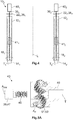
- FIG. 4 illustrated second embodiment of the adjusting device 10 2 is largely identical to the first embodiment of the adjusting device 10 1 shown in Figure 3 constructed.
- the first and second threaded spindle 18 1 , 18 2 rotatably mounted, however, the first and second threaded spindle 18 1 , 18 2 are not directly connected to the output shaft 39 of the first and second drive motor 40 1 , 40 2 . Rather, the first threaded spindle 18 1 at one end to the first gear 22 1 and the second threaded spindle 18 2 is connected at one end to the second gear 22 2 .
- the first gear 22 1 and the second gear 22 2 as a planetary gear 38 1 , 38 2 executed.
- Each of the planetary gear 38 1 , 38 2 is the drive side connected to the output shaft 39 of the first and the second drive motor 40 1 , 40 2 . Consequently, the first threaded spindle 18 1 is assigned a first drive motor 40 1 and the second threaded spindle 40 2 is assigned a second drive motor 26.
- the first drive motor 40 1 and its output shaft 39 and the first planetary gear 38 1 are aligned with the axis of rotation T of the first threaded spindle 18 1 and the second drive motor 40 2 and its output shaft 39 and the second planetary gear 38 2 in alignment with the axis of rotation T of the second threaded spindle 18 2 arranged.
- the first planetary gear 381 and the second planetary gear 382 may be formed as conventional planetary gear or as so-called helical gear planetary gear 43.
- Such a helical gear planetary gear 43 is in the Figures 5A and 5B each shown in parts and not mounted.
- the output shaft 39 has a fferradvertechnikung 45, which is why the output shaft 39 is also referred to as SSradwelle 47 and which is rotatable about a fferradwellenachse A SW .
- a planetary carrier 49 is present, in which in this case three planet gears 51 (see, in particular FIG. 5B ) are rotatably mounted in each case about a planetary gear axis AP.
- the planet gears 51 have a Planetenradvertechnikung 53, which is adapted to the fferradvertechnikung 45, so that a largely optimal engagement between the ringradwelle 47 and the planetary gears 51 is made possible.
- a special feature of the helical gear planet gears 43 is that the planetary gear axes AP is skewed to the helical shaft axis A SW .
- the helical gear planetary gear 43 and a ring gear 53 which is designed in this case as a mecanicschraubrad 55 with internal teeth 59, wherein the internal teeth 59 is adapted to the Planetenradvertechnikung 53 such that a largely optimal engagement between the planetary gears 51st and the mecanicschraubrad 47 is provided.
- the planet carrier 49 is rotatably mounted in réelleschraubrad 55.
- either the planetary carrier 49 or the réelleschraubrad 47 can be fixed in a rotating plexradwelle 47 and rotate the other part.
- the Certainlyschraubrad 47 rotatably with a housing, not shown, of the drive motor 40 and the threaded spindle rotatably connected to the planet carrier 49.
- the helical gear shaft axis Asw and the rotational axis T coincide.
- FIG. 6A is a third embodiment of the proposed adjustment 10 3 also shown with reference to a basic plan view.
- the adjusting device 10 2 has the carrier 24 extending between the first and the second upper rail 14 1 , 14 2 , on which the drive motor 26 is arranged.
- the first gear 22 1 is configured as a first worm gear 42 1 and the second gear 22 2 as a second worm gear 42 2 .
- the first worm gear 42 1 is in FIG. 6B shown separately.
- the worm gears 42 1 , 42 2 each comprise a worm 44 with a worm axis 46 and a worm wheel 48 with a worm wheel axis 50, which enclose an axial angle ⁇ .
- the axial angle ⁇ is less than 90 °, in about 30 °.
- the worm gears 42 1 , 42 2 are relative to the displacement axis L offset by a distance D to the drive motor 26 is arranged.
- the powertrain 28 includes a distance bridging means 52 which is formed as a flexible first drive shaft 54 1 and a flexible second drive shaft 54 2 .
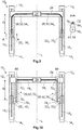
- FIG. 7 is a fourth embodiment of the adjustment 10 4 according to the invention again shown by a basic plan view.
- the first gear 22 1 as a first spur gear 58 1 and the second gear 22 2 designed as a second spur gear 58 2 and arranged offset by the distance D along the displacement axis L to the drive motor 26.
- the drive train 28 again comprises the flexible drive shafts 54 1 54 2 , which are non-rotatably connected at one end to an upper spur gear 60.
- the upper spur gear 60 is in meshing engagement with a rotatable lower spur gear 62, which is designed as the spindle nut 41 and cooperates with the threaded spindle 18 1 .
- the flexible drive shafts 54 1 , 54 2 are connected to the other end with a further gear 64, in this case with a motor worm gear 66, which is the drive side connected to an output shaft 68 of the drive motor 26.
- a direct connection to the drive motor 26 is also conceivable.
- the further gear 64 serves as a transfer case.
- the drive train 28, the spur gear 58 and the threaded spindle 18 provide a total ratio i ready.
- the threaded spindles 18 1 , 18 2 a thread normal pitch PN, which is between 2.5 and 3.5 mm, as is the case in known adjusting 10P.
- the flexible drive shafts 54 1 , 54 2 extend above the upper rails 14 1 , 14 2 and do not pass through the space between the two lower rails 12 1 , 12 2 , making this even better for the Arrangement of components makes usable.
- the axial distance X between the upper spur gear 60 and the lower spur gear 62 is selected correctly.
- the axial distance X must be large enough so that the upper spur gear 60 protrudes far enough from the cavity 16 to connect the flexible drive shaft 54 with the upper spur gear 60 can.
- the axial distance X is set at spur gears 58 of the diameters of the upper spur gear 60 and the lower spur gear 62.
- the diameter of the lower spur gear 62 can not be chosen arbitrarily large, since it otherwise abuts against the upper rail 12 or the lower rail 14.
- the further gear 64 already reduces the rotational speed of the flexible drive shafts 54 1 , 54 1 by a certain amount, so that the spur gear 58 only has to make a small or no translation.
- the lower the translations the closer the diameters of the upper and lower spur gears 60, 62 approach, whereby the axial distance X can be adapted to the structural conditions.
- the noise in spur gears is kept low at low speeds.
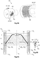
- FIG. 8 is a fifth embodiment of the adjusting device 10 5 according to the invention again shown by a basic plan view.
- the structure of the fifth embodiment is similar to that of the fourth embodiment, but the drive train 28 does not have the further gear 64.
- the threaded spindles 18 1 , 18 2 have a thread pitch P which is smaller by about 60 to 70% than the thread normal pitch P, for example of the fourth exemplary embodiment. Due to the lower thread pitch P, the spur gear 58 1 , 58 2 a low gear ratio near 1 on.
- the axial distance X can hereby be adapted to the structural conditions without changing the overall transmission ratio i.
- FIG. 9 is a sixth embodiment of the adjusting device 10 6 according to the invention again shown by a basic plan view.
- the drive train 28 comprises a first belt transmission 70 1 and a second belt transmission 70 2 , which are offset by the distance D along the displacement axis L to the drive motor 26.
- the first belt transmission 70 1 has on the drive side a first drive wheel 72 1 , which is rotatably connected to the flexible first drive shaft 54 1 .
- the first belt transmission 70 1 on the output side comprises a first output gear 74 1 , which is configured as the spindle nut 41 and cooperates with the first threaded spindle 18 1 .
- a first belt 76 1 is arranged between the first drive wheel 72 1 and the first driven gear 74 1 .
- the second belt transmission 70 2 is constructed accordingly.
- the drive shafts 54 1 , 54 2 extend above the upper rails 14 1 , 14 2 .
- FIG. 10 is a seventh embodiment of the adjusting device 10 7 according to the invention again shown with reference to a basic plan view.
- the drive train 28 includes the first and the second belt transmission 70 1 , 70 2 , but which are arranged slightly differently.
- the powertrain 28 includes two drive shafts 78 1 , 78 2 that may be rigid and that extend linearly along the beam 24.
- the first gear 22 1 and the second gear 22 2 are formed as the worm gear 42 1 , 42 2 with an axial angle ⁇ of 90 ° and arranged offset by the distance D along the displacement axis L to the drive motor 26.
- the belt transmissions 70 1 , 70 2 are arranged between the drive shafts 78 1 , 78 2 and the worm gears 42 1 , 42 2 .
- the first belt transmission 70 on the drive side 1 comprises a rotationally fixed to the drive shaft 78 1 connected to first drive wheel 72 1 and the output side of the cooperating with the worm gear 42 first driven gear 74 1. 1
- the arranged between the first drive gear 72 1 and the first driven gear 74 1 1 first belt 76 runs parallel to the upper rail 14 1, whereby the distance D is bypassed.
- the first belt transmission 70 1 is arranged in a housing 80.
- the second belt transmission 70 2 is constructed analogously to the first belt transmission 70 1 .
Landscapes
- Engineering & Computer Science (AREA)
- Mechanical Engineering (AREA)
- Aviation & Aerospace Engineering (AREA)
- Transportation (AREA)
- General Engineering & Computer Science (AREA)
- Seats For Vehicles (AREA)
- Transmission Devices (AREA)
Applications Claiming Priority (1)
| Application Number | Priority Date | Filing Date | Title |
|---|---|---|---|
| DE102017101996.0A DE102017101996A1 (de) | 2017-02-01 | 2017-02-01 | Verstellvorrichtung zum Verstellen eines Fahrzeugsitzes entlang einer Verschiebeachse |
Publications (2)
| Publication Number | Publication Date |
|---|---|
| EP3358218A2 true EP3358218A2 (fr) | 2018-08-08 |
| EP3358218A3 EP3358218A3 (fr) | 2018-11-07 |
Family
ID=61054221
Family Applications (1)
| Application Number | Title | Priority Date | Filing Date |
|---|---|---|---|
| EP18153616.0A Withdrawn EP3358218A3 (fr) | 2017-02-01 | 2018-01-26 | Dispositif de réglage destiné au réglage d'un siège de véhicule le long d'un axe de déplacement |
Country Status (5)
| Country | Link |
|---|---|
| US (1) | US20180215287A1 (fr) |
| EP (1) | EP3358218A3 (fr) |
| KR (1) | KR102021514B1 (fr) |
| CN (1) | CN108372803A (fr) |
| DE (1) | DE102017101996A1 (fr) |
Cited By (4)
| Publication number | Priority date | Publication date | Assignee | Title |
|---|---|---|---|---|
| DE102022202333A1 (de) | 2021-11-16 | 2023-05-17 | Adient Us Llc | Getriebeanordnung, Längseinsteller sowie Fahrzeugsitz |
| WO2023089378A1 (fr) | 2021-11-16 | 2023-05-25 | Adient Us Llc | Agencement d'engrenage, dispositif de réglage longitudinal et siège de véhicule |
| WO2025045974A1 (fr) * | 2023-08-31 | 2025-03-06 | Faurecia Sièges d'Automobile | Dispositif de mobilisation d'un siège automobile d'avant en arrière |
| WO2025133081A1 (fr) | 2023-12-21 | 2025-06-26 | Hutchinson | Système de transmission pour synchroniser un mouvement d'un objet monté sur au moins deux glissières paralleles |
Families Citing this family (15)
| Publication number | Priority date | Publication date | Assignee | Title |
|---|---|---|---|---|
| DE102019103476B4 (de) | 2018-12-07 | 2024-02-01 | Keiper Seating Mechanisms Co., Ltd. | Längseinsteller für einen fahrzeugsitz, sowie fahrzeugsitz |
| JP7415125B2 (ja) * | 2019-08-02 | 2024-01-17 | テイ・エス テック株式会社 | スライドレール装置及び車両用シート |
| WO2021048173A1 (fr) | 2019-09-09 | 2021-03-18 | Adient Engineering and IP GmbH | Ensemble siège à dispositif anticollision |
| KR102244747B1 (ko) * | 2019-10-28 | 2021-04-27 | 주식회사 서연이화 | 차량용 무중력 시트 |
| KR102284693B1 (ko) * | 2019-11-21 | 2021-08-02 | 현대트랜시스 주식회사 | 차량용 시트의 이동장치 및 이의 제어방법 |
| DE102020202523A1 (de) | 2020-02-27 | 2021-09-02 | Brose Fahrzeugteile SE & Co. Kommanditgesellschaft, Coburg | Verstelleinrichtung für einen Fahrzeugsitz |
| US11667358B2 (en) * | 2020-05-29 | 2023-06-06 | Pelican International Inc. | Watercraft |
| TWM607355U (zh) * | 2020-07-29 | 2021-02-11 | 模帝科電子科技股份有限公司 | 具差速機構傳動之支撐裝置 |
| KR102547391B1 (ko) * | 2021-02-10 | 2023-06-23 | 대동모벨시스템 주식회사 | 차량용 시트 이동 장치 |
| DE102021107896A1 (de) * | 2021-03-29 | 2022-09-29 | Faurecia Autositze Gmbh | Kraftfahrzeugsitz |
| KR102571433B1 (ko) | 2021-07-13 | 2023-08-28 | 현대트랜시스 주식회사 | 전동식 시트레일 이송장치 |
| FR3125482A1 (fr) | 2021-07-23 | 2023-01-27 | Faurecia Sièges d'Automobile | Glissière pour siège de véhicule, dispositif de glissière, ensemble de siège de véhicule et véhicule automobile |
| DE102021119681A1 (de) | 2021-07-29 | 2023-02-02 | Adient Us Llc | Längseinsteller für einen fahrzeugsitz, sowie fahrzeugsitz |
| DE102022208885A1 (de) | 2022-05-31 | 2023-11-30 | Adient Us Llc | Längseinsteller für einen Fahrzeugsitz sowie Fahrzeugsitz |
| US20250303930A1 (en) | 2022-05-31 | 2025-10-02 | Adient Us Llc | Longitudinal adjuster for a vehicle seat, and vehicle seat |
Citations (2)
| Publication number | Priority date | Publication date | Assignee | Title |
|---|---|---|---|---|
| US6260922B1 (en) * | 1998-08-12 | 2001-07-17 | Ernst-Reiner Frohnhaus | Vehicle seat with an adjusting device provided with a spindle and an associated spindle nut |
| DE102008017006A1 (de) * | 2007-06-19 | 2008-12-24 | C. Rob. Hammerstein Gmbh & Co. Kg | Stellantrieb für ein Kraftfahrzeug mit einem Getriebegehäuse |
Family Cites Families (42)
| Publication number | Priority date | Publication date | Assignee | Title |
|---|---|---|---|---|
| US2931424A (en) * | 1955-09-26 | 1960-04-05 | Ferro Stamping Co | Seat adjusting mechanism |
| US3043552A (en) * | 1960-03-03 | 1962-07-10 | Gen Motors Corp | Power transmitting mechanism for vehicle seats |
| IT1209853B (it) * | 1980-03-21 | 1989-08-30 | Ti Cox Ltd | Perfezionamento nelle strutture per la installazione di sedili di veicoli |
| FR2580759B1 (fr) * | 1985-04-18 | 1990-02-23 | Marchal Equip Auto | Dispositif de commande du deplacement d'un element, notamment d'un siege ou des parties d'un siege d'un vehicule automobile, par rapport a un bati |
| JPS6478720A (en) * | 1987-09-22 | 1989-03-24 | Nippon Gia Kogyo Kk | Corrective tooth cutting method for saddle type worm gear |
| JP3089680B2 (ja) * | 1991-03-20 | 2000-09-18 | アイシン精機株式会社 | 車両用シートスライド装置 |
| US5222402A (en) * | 1991-09-05 | 1993-06-29 | Rockwell International Corporation | Horizontal seat position adjuster |
| FR2711100B1 (fr) * | 1993-10-14 | 1995-12-15 | Bfa | Perfectionnements aux dispositifs de réglage des sièges de véhicules. |
| US5575531A (en) * | 1993-12-15 | 1996-11-19 | Itt Corporation | Vehicle power seat adjuster with end driven lead screw actuation |
| US6093126A (en) * | 1996-10-16 | 2000-07-25 | Fleytman; Yakov | Transmission device |
| US6055877A (en) * | 1998-06-12 | 2000-05-02 | Buehler Products, Inc. | Power seat track motor assembly |
| DE19860910B4 (de) * | 1998-12-31 | 2007-07-26 | C. Rob. Hammerstein Gmbh & Co. Kg | Fahrzeugsitz mit einem Sitzgestell und einem Untergestell |
| US6499712B1 (en) * | 1999-02-03 | 2002-12-31 | Tecla Company, Inc. | Electric seat slide and actuator system |
| DE10062217B4 (de) * | 2000-12-13 | 2006-08-03 | Keiper Gmbh & Co.Kg | Längseinsteller für einen Fahrzeugsitz |
| ES2393723T3 (es) * | 2001-03-05 | 2012-12-27 | Ims Gear Gmbh | Dispositivo para un ajuste longitudinal de asiento, en particular dentro de un automóvil |
| FR2847313B1 (fr) * | 2002-11-18 | 2005-01-14 | Inderflex Technoflex | Dispositif de transmission d'un mouvement de rotation comprenant des zones formant palier |
| DE10362040B4 (de) * | 2003-02-24 | 2009-05-07 | C. Rob. Hammerstein Gmbh & Co. Kg | Spindelgetriebe für eine Verstellvorrichtung in einem Kraftfahrzeugsitz |
| US7472939B2 (en) * | 2003-03-11 | 2009-01-06 | Inderflex-Technoflex | Device for transmitting a rotational movement by means of a smooth shaft |
| DE10325954B3 (de) | 2003-06-07 | 2004-07-15 | Faurecia Autositze Gmbh & Co. Kg | Kraftfahrzeugsitz mit mindestens einer Verstellfunktion |
| DE10337475A1 (de) * | 2003-08-08 | 2005-03-03 | Brose Fahrzeugteile Gmbh & Co. Kommanditgesellschaft, Coburg | Verstellgetriebe für ein Kraftfahrzeug |
| US7367574B2 (en) * | 2003-10-10 | 2008-05-06 | Horst Leitner | Drive systems for retractable vehicle step |
| JP4419518B2 (ja) * | 2003-10-30 | 2010-02-24 | アイシン精機株式会社 | シートスライド装置 |
| US7775595B2 (en) * | 2004-02-06 | 2010-08-17 | Schukra Of North America | Drive mechanism |
| KR100587687B1 (ko) * | 2004-07-27 | 2006-06-08 | 삼성전자주식회사 | 원자층 증착법을 이용한 박막 형성 방법과 그 장치 |
| DE102004043630C5 (de) * | 2004-09-07 | 2011-08-18 | Johnson Controls GmbH, 51399 | Verstellvorrichtung, insbesondere für den Sitz eines Fahrzeugs |
| FR2882974B1 (fr) | 2005-03-14 | 2008-11-07 | Faurecia Sieges Automobile | Mecanisme de reglage a vis, glissiere comportant un tel mecanisme de reglage et siege comportant une telle glissiere |
| DE202006004613U1 (de) | 2005-10-18 | 2007-03-01 | Brose Fahrzeugteile Gmbh & Co. Kommanditgesellschaft, Coburg | Antriebsvorrichtung für eine Verstelleinrichtung in Kraftfahrzeugen sowie Sitzverstelleinrichtung |
| FR2906768B1 (fr) * | 2006-10-09 | 2009-01-16 | Faurecia Sieges Automobile | Siege de vehicule a glissieres motorisees |
| KR101406672B1 (ko) * | 2006-10-23 | 2014-06-11 | 인티어 오토모티브, 인크. | 동력 좌석 트랙 구동 조립체 |
| DE202008010921U1 (de) * | 2008-08-12 | 2010-01-07 | Brose Fahrzeugteile Gmbh & Co. Kommanditgesellschaft, Coburg | Verstellgetriebe für eine Verstelleinrichtung eines Kraftfahrzeugs |
| DK2166252T3 (da) * | 2008-09-17 | 2012-12-10 | Karlheinz Baumeister | Snekkedrev |
| JP5370845B2 (ja) * | 2008-10-09 | 2013-12-18 | Ntn株式会社 | ウォームギア用軸受装置および自動車用パワーシートのシートスライド機構用ウォームギア |
| DE102009058333B4 (de) | 2009-12-15 | 2015-01-08 | Johnson Controls Components Gmbh & Co. Kg | Längseinsteller für einen Fahrzeugsitz |
| DE102010053892B4 (de) * | 2010-12-09 | 2015-01-29 | Airbus Operations Gmbh | Sitzverstellvorrichtung sowie Luft-oder Raumfahrzeug |
| WO2012104395A2 (fr) * | 2011-02-02 | 2012-08-09 | Continental Teves Ag & Co. Ohg | Module de tambour de frein fonctionnant à l'aide d'un moteur électrique |
| US8967012B2 (en) * | 2011-08-17 | 2015-03-03 | Gm Global Technology Operations, Llc | Double involute pinion-face gear drive system |
| JP5692536B2 (ja) * | 2011-10-24 | 2015-04-01 | アイシン精機株式会社 | シート駆動装置 |
| DE102011085873A1 (de) * | 2011-11-07 | 2013-05-08 | C. Rob. Hammerstein Gmbh & Co. Kg | Verstellgetriebe, insbesondere zur Sitzlängsverstellung eines Kfz-Sitzes |
| WO2014093266A1 (fr) * | 2012-12-10 | 2014-06-19 | Key Safety Systems Inc. | Ensemble présentateur d'attache de ceinture de sécurité |
| DE102013105095B4 (de) | 2013-02-14 | 2018-05-30 | Adient Luxembourg Holding S.À R.L. | Verstellvorrichtung für einen Fahrzeugsitz |
| JP6098276B2 (ja) | 2013-03-26 | 2017-03-22 | アイシン精機株式会社 | シートスライド装置 |
| US9243700B1 (en) * | 2015-01-20 | 2016-01-26 | Robert Harold DeBoth | Coupled worm planetary gear continuously variable ratio transmission |
-
2017
- 2017-02-01 DE DE102017101996.0A patent/DE102017101996A1/de not_active Withdrawn
-
2018
- 2018-01-26 EP EP18153616.0A patent/EP3358218A3/fr not_active Withdrawn
- 2018-01-31 KR KR1020180012075A patent/KR102021514B1/ko not_active Expired - Fee Related
- 2018-02-01 US US15/886,555 patent/US20180215287A1/en not_active Abandoned
- 2018-02-01 CN CN201810099342.1A patent/CN108372803A/zh active Pending
Patent Citations (2)
| Publication number | Priority date | Publication date | Assignee | Title |
|---|---|---|---|---|
| US6260922B1 (en) * | 1998-08-12 | 2001-07-17 | Ernst-Reiner Frohnhaus | Vehicle seat with an adjusting device provided with a spindle and an associated spindle nut |
| DE102008017006A1 (de) * | 2007-06-19 | 2008-12-24 | C. Rob. Hammerstein Gmbh & Co. Kg | Stellantrieb für ein Kraftfahrzeug mit einem Getriebegehäuse |
Cited By (6)
| Publication number | Priority date | Publication date | Assignee | Title |
|---|---|---|---|---|
| DE102022202333A1 (de) | 2021-11-16 | 2023-05-17 | Adient Us Llc | Getriebeanordnung, Längseinsteller sowie Fahrzeugsitz |
| WO2023089378A1 (fr) | 2021-11-16 | 2023-05-25 | Adient Us Llc | Agencement d'engrenage, dispositif de réglage longitudinal et siège de véhicule |
| DE102022202333B4 (de) * | 2021-11-16 | 2026-02-12 | Adient Us Llc | Getriebeanordnung, Längseinsteller sowie Fahrzeugsitz |
| WO2025045974A1 (fr) * | 2023-08-31 | 2025-03-06 | Faurecia Sièges d'Automobile | Dispositif de mobilisation d'un siège automobile d'avant en arrière |
| WO2025133081A1 (fr) | 2023-12-21 | 2025-06-26 | Hutchinson | Système de transmission pour synchroniser un mouvement d'un objet monté sur au moins deux glissières paralleles |
| FR3157499A1 (fr) * | 2023-12-21 | 2025-06-27 | Hutchinson | Système de transmission pour synchroniser un mouvement d’un objet monté sur au moins deux glissières paralleles |
Also Published As
| Publication number | Publication date |
|---|---|
| DE102017101996A1 (de) | 2018-08-02 |
| CN108372803A (zh) | 2018-08-07 |
| KR102021514B1 (ko) | 2019-09-16 |
| EP3358218A3 (fr) | 2018-11-07 |
| KR20180089862A (ko) | 2018-08-09 |
| US20180215287A1 (en) | 2018-08-02 |
Similar Documents
| Publication | Publication Date | Title |
|---|---|---|
| EP3358218A2 (fr) | Dispositif de réglage destiné au réglage d'un siège de véhicule le long d'un axe de déplacement | |
| EP3707334B1 (fr) | Utilisation d'une unité de réglage pour applications dans le domaine technique de l'automobile | |
| EP2595854B1 (fr) | Levier de direction à double pignon | |
| DE102017205721B4 (de) | Getriebeeinheit für ein Kraftfahrzeug | |
| DE10320328B4 (de) | Untersetzungsgetriebe für eine Verstellvorrichtung eines Kraftfahrzeugsitzes | |
| EP3844046B1 (fr) | Colonne de direction steer-by-wire à réglage électrique et véhicule automobile | |
| DE102014103879A1 (de) | Lenksäule für ein Kraftfahrzeug, Gewindestange und Spindelmutter | |
| WO2015185036A1 (fr) | Engrenage planétaire | |
| WO2014090468A1 (fr) | Dispositif de transmission et amplificateur de force de freinage électromotorisé | |
| EP2037069A2 (fr) | Dispositif d'entraînement, notamment pour lève-glace de voiture | |
| DE112016002670T5 (de) | Getriebeanordnung für elektrische Servolenkung | |
| EP3276212A1 (fr) | Systeme de raccordement d'un composant tel un arbre, un moyeu, une douille ou similaire a une roue dentee, la roue dentee presentant une denture helicoïdale | |
| WO2019121626A1 (fr) | Ensemble de transmission pour un motoréducteur d'un frein à actionnement électrique, motoréducteur, système de frein à main et système de pédale de frein | |
| DE102012010547B4 (de) | Rangierantrieb für einen Anhänger | |
| DE102017130073B3 (de) | Niveauverstellvorrichtung für ein Kraftfahrzeug | |
| DE102020204542B4 (de) | Fahrzeugtüraktuator, Fahrzeugtür und Fahrzeug | |
| DE102023119261A1 (de) | Verteilergetriebe zu einem drehrichtungsabhängigen Antrieb von zwei Abtriebsrädern und Luftausströmer mit dem Verteilergetriebe | |
| EP1948420A1 (fr) | Transmission pour extrudeuse a double vis | |
| DE202017102027U1 (de) | Getriebeeinheit für ein Kraftfahrzeug | |
| DE102011051529A1 (de) | Lenkgetriebe mit einer mechanischen begrenzung des abtriebswellenwinkels für schwere nutzkraftwagen mit elektrischer lenkunterstützung | |
| DE102018104024B4 (de) | Stellelement für ein Luftleitelement eines Kraftfahrzeugs | |
| WO2022152520A1 (fr) | Actionneur de portière de véhicule, portière de véhicule et véhicule | |
| DE102024107399B3 (de) | Antrieb für eine Tür oder ein Fenster mit verbessertem Wirkungsgrad | |
| WO2019101384A1 (fr) | Mecanisme de transmission pour un système de direction | |
| DE102017205724A1 (de) | Getriebeeinheit für ein Kraftfahrzeug |
Legal Events
| Date | Code | Title | Description |
|---|---|---|---|
| PUAI | Public reference made under article 153(3) epc to a published international application that has entered the european phase |
Free format text: ORIGINAL CODE: 0009012 |
|
| STAA | Information on the status of an ep patent application or granted ep patent |
Free format text: STATUS: THE APPLICATION HAS BEEN PUBLISHED |
|
| AK | Designated contracting states |
Kind code of ref document: A2 Designated state(s): AL AT BE BG CH CY CZ DE DK EE ES FI FR GB GR HR HU IE IS IT LI LT LU LV MC MK MT NL NO PL PT RO RS SE SI SK SM TR |
|
| AX | Request for extension of the european patent |
Extension state: BA ME |
|
| PUAL | Search report despatched |
Free format text: ORIGINAL CODE: 0009013 |
|
| RIN1 | Information on inventor provided before grant (corrected) |
Inventor name: KOOP, MATTHIAS Inventor name: GEIGES, CHRISTIAN Inventor name: SYNOVZIK, WILFRIED Inventor name: FECHLER, JENS Inventor name: HENGSTLER, MANUEL |
|
| AK | Designated contracting states |
Kind code of ref document: A3 Designated state(s): AL AT BE BG CH CY CZ DE DK EE ES FI FR GB GR HR HU IE IS IT LI LT LU LV MC MK MT NL NO PL PT RO RS SE SI SK SM TR |
|
| AX | Request for extension of the european patent |
Extension state: BA ME |
|
| RIC1 | Information provided on ipc code assigned before grant |
Ipc: F16H 1/30 20060101AFI20180929BHEP Ipc: F16H 25/20 20060101ALI20180929BHEP Ipc: B60N 2/06 20060101ALI20180929BHEP Ipc: B60N 2/02 20060101ALI20180929BHEP |
|
| STAA | Information on the status of an ep patent application or granted ep patent |
Free format text: STATUS: REQUEST FOR EXAMINATION WAS MADE |
|
| 17P | Request for examination filed |
Effective date: 20190416 |
|
| RBV | Designated contracting states (corrected) |
Designated state(s): AL AT BE BG CH CY CZ DE DK EE ES FI FR GB GR HR HU IE IS IT LI LT LU LV MC MK MT NL NO PL PT RO RS SE SI SK SM TR |
|
| STAA | Information on the status of an ep patent application or granted ep patent |
Free format text: STATUS: EXAMINATION IS IN PROGRESS |
|
| 17Q | First examination report despatched |
Effective date: 20210209 |
|
| STAA | Information on the status of an ep patent application or granted ep patent |
Free format text: STATUS: THE APPLICATION IS DEEMED TO BE WITHDRAWN |
|
| 18D | Application deemed to be withdrawn |
Effective date: 20210622 |