EP2037249A2 - Dispositif de mesure de grandeurs mécaniques, procédé de mesure de grandeurs mécaniques et utilisation d'un dispositif de mesure de grandeurs mécaniques - Google Patents
Dispositif de mesure de grandeurs mécaniques, procédé de mesure de grandeurs mécaniques et utilisation d'un dispositif de mesure de grandeurs mécaniques Download PDFInfo
- Publication number
- EP2037249A2 EP2037249A2 EP08015406A EP08015406A EP2037249A2 EP 2037249 A2 EP2037249 A2 EP 2037249A2 EP 08015406 A EP08015406 A EP 08015406A EP 08015406 A EP08015406 A EP 08015406A EP 2037249 A2 EP2037249 A2 EP 2037249A2
- Authority
- EP
- European Patent Office
- Prior art keywords
- measuring mechanical
- quantities according
- measuring
- mechanical quantities
- recess
- Prior art date
- Legal status (The legal status is an assumption and is not a legal conclusion. Google has not performed a legal analysis and makes no representation as to the accuracy of the status listed.)
- Withdrawn
Links
Images

Classifications
-
- G—PHYSICS
- G01—MEASURING; TESTING
- G01L—MEASURING FORCE, STRESS, TORQUE, WORK, MECHANICAL POWER, MECHANICAL EFFICIENCY, OR FLUID PRESSURE
- G01L5/00—Apparatus for, or methods of, measuring force, work, mechanical power, or torque, specially adapted for specific purposes
- G01L5/04—Apparatus for, or methods of, measuring force, work, mechanical power, or torque, specially adapted for specific purposes for measuring tension in flexible members, e.g. ropes, cables, wires, threads, belts or bands
- G01L5/10—Apparatus for, or methods of, measuring force, work, mechanical power, or torque, specially adapted for specific purposes for measuring tension in flexible members, e.g. ropes, cables, wires, threads, belts or bands using electrical means
- G01L5/101—Apparatus for, or methods of, measuring force, work, mechanical power, or torque, specially adapted for specific purposes for measuring tension in flexible members, e.g. ropes, cables, wires, threads, belts or bands using electrical means using sensors inserted into the flexible member
Definitions
- the present invention relates to a device for measuring mechanical quantities with the features of the preamble of patent claim 1 and a method for measuring mechanical quantities and the use of a device for measuring mechanical quantities.
- a substantially rectangular flat iron is provided with three recesses or holes, which have their center on the longitudinal axis of the device, wherein the longitudinal axis is at the same time an axis of symmetry with respect to the arrangement of the holes of the devices.
- Such devices are used, for example, for measuring tensile forces in a range of 0 to 400 kN.
- the two outer holes are provided with bolts, are introduced via the tensile forces in the load cell.
- the bolts are completely covered by the bore.
- the third hole contains strain gauges.
- the device for measuring mechanical quantities comprises first receptacles for receiving first means, wherein force can be introduced into the device by means of the at least two first means. At least one second means is provided, via which mechanical variables can be detected, and at least one second recess.
- the first recesses do not completely surround the first means and at least two opposing first recesses communicate with a second recess.
- the first recesses and the second recesses form a common recess.
- the recesses form a continuous opening, ie they completely penetrate the material of the device.
- the longitudinal expansion of the device is translated to a bending strain. This can be measured in the transverse direction of the change in length of the device, from which results the existing tensile force.
- the translation of the longitudinal expansion to a bending elongation is made possible in that the first recesses do not completely enclose the first means and thus the enclosure of the second recess undergoes an almost unimpeded deflection as a result of the change in length of the device. Since the length change in the transverse direction is larger than the length change in the longitudinal direction, therefore, can be measured more easily and accurately.
- Another consequence is that as a second means strain gauges do not necessarily have to be used, but other measuring systems such as optical methods can be used.
- Another advantage is that several measurement methods can be used simultaneously, so that the measurement data acquisition takes place redundantly. This can be an advantage in safety-critical applications.
- first recesses are substantially circular. This makes it possible to use first means of circular cross-section in connection with the device.
- the first recesses may be formed in this case, for example, by a continuous bore, which has a gap to the second recess, which connects the first recess with the second recess. This results in the advantage that, for example, when subjected to a tensile force by first means, the tensile force is not already proportionately absorbed by the enclosure of the first recess, but is almost lossless introduced into the enclosure of the second recess.
- the common recess formed by the first and second recesses has substantially rounded contours.
- voltage peaks can be avoided and a uniform flow of force can be achieved in the device.
- the only corners of the contour arise only at the gap, which connects the first with the second recess.
- the other contours are rounded without exception, so that there are substantially rounded contours of the common recess formed by the first and second recesses.
- the first means may be designed as a bolt. This makes it possible, the inventive device z. B. in conjunction with existing measuring devices which have bolts to use.
- the device has an elliptical or substantially circular basic shape.
- Such a shape makes it possible to take advantage of bending deformations for the measurement. At the same time allows such a form to transmit large forces through the device.
- Elliptical basic shapes with the longer axis in the direction of force make it possible to identify the larger occurring deformations under load in the transverse direction. This makes it possible to measure the deformations in the transverse direction.
- the essential advantage of such a basic form is that the power flow remains as undisturbed as possible.
- a symmetry half with a first recess and the part of a second recess may be approximated to the shape of a torso with a head.
- the first recess forms the head, the gap connecting the first recess with the second recess, the neck and the part of the second recess the torso.
- Such a contour allows an optimal power flow and a uniform stress distribution in the device. In particular, this prevents that voltage peaks occur. In addition, disturbances due to the shape are reduced.
- first recesses and a second recess may be provided.
- the first two recesses can lie on the axis of symmetry, the symmetry axis being congruent with the direction of the force.
- the webs may lie on an axis of symmetry of the device.
- the symmetrical design enables an optimal power flow and a uniform stress distribution.
- tensile forces shear forces or strain can be detected in at least one spatial direction.
- the invention relates to a method for measuring mechanical variables, wherein at least one mechanical variable is determined by means of a device according to claim 1 to 17 via the second means.
- a method for measuring mechanical variables has the advantages that mechanical variables such. As tensile forces with less influence of disturbances, overall more accurate, easier and can be detected with cheaper measuring systems. In addition, it becomes possible to detect the mechanical quantity to be detected redundantly by using different detection systems.
- the invention relates to the use of a device for measuring mechanical quantities according to claim 1 to 17, wherein by means of the device, the mechanical stress of components is detected. It can be provided that by means of the device tensile forces, shear forces or strain are detected in at least one spatial direction.
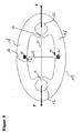
- FIG. 1 shows the inventive device for measuring mechanical quantities in a first embodiment.
- the device 10 has an elliptical basic shape.
- the device 10 has two opposing first recesses 12, the centers of which lie on the axis of symmetry S1, which is at the same time the force introduction axis of the forces F.
- the first recesses 12 are provided for receiving bolts (not shown) for introducing force, the first recesses 12 not completely enclosing the bolts.
- the first recesses 12 are connected to the second recess 16 through the gap 14.
- the first recesses 12 thus form a common recess via the gaps 14 with the second recess 16.
- the common recess formed by the first and second recesses 10, 12 has substantially rounded contours, the single corners
- the basic shape of the device 10 has in this embodiment two mutually perpendicular symmetry axes S1 and S2, wherein the first axis of symmetry S1 passes through the centers of the first recesses 12 and the second axis of symmetry S2, the opposite first Recesses 12 images each other.
- the symmetry axis S2 is at the same time the measuring direction.
- the second axis of symmetry S2 divides the common recess into two halves, one half of which approximates the shape of a torso with a head.
- a total of four strain gauges 30 are mounted on the device 10, two strain gauges each being mounted on the top of the device on the enclosure 18 of the second recess 16 on the second axis of symmetry and two further strain gauges 30 are mounted on the side surface of the inside of the second recess 16 , Since the enclosure 18 of the second recess is subject to the greatest bending deformation, the bend is detected here and the measurement signal is tapped. Furthermore, it is provided to detect the bending deformations optically, as well as by means of the strain gauges and (not shown) optical measuring method tensile force, strain, stress distribution, shear forces, torsion and material properties are detected.
- FIG. 2 shows a device 10 'in a further embodiment.
- This device has all the features of the first embodiment, in addition, T-shaped webs 40 are provided in reverse. At the inverted T-shaped webs 40 not shown strain gauges 30 are attached.
- the device 10 ' is made of stainless steel in this embodiment.
Landscapes
- Chemical & Material Sciences (AREA)
- Analytical Chemistry (AREA)
- Physics & Mathematics (AREA)
- General Physics & Mathematics (AREA)
- Force Measurement Appropriate To Specific Purposes (AREA)
- Investigating Strength Of Materials By Application Of Mechanical Stress (AREA)
- Length Measuring Devices With Unspecified Measuring Means (AREA)
Applications Claiming Priority (1)
| Application Number | Priority Date | Filing Date | Title |
|---|---|---|---|
| DE102007044225A DE102007044225A1 (de) | 2007-09-17 | 2007-09-17 | Vorrichtung zum Messen mechanischer Größen, Verfahren zum Messen mechanischer Größen sowie Verwendung einer Vorrichtung zum Messen mechanischer Größen |
Publications (2)
| Publication Number | Publication Date |
|---|---|
| EP2037249A2 true EP2037249A2 (fr) | 2009-03-18 |
| EP2037249A3 EP2037249A3 (fr) | 2014-05-28 |
Family
ID=40130893
Family Applications (1)
| Application Number | Title | Priority Date | Filing Date |
|---|---|---|---|
| EP08015406.5A Withdrawn EP2037249A3 (fr) | 2007-09-17 | 2008-09-01 | Dispositif de mesure de grandeurs mécaniques, procédé de mesure de grandeurs mécaniques et utilisation d'un dispositif de mesure de grandeurs mécaniques |
Country Status (3)
| Country | Link |
|---|---|
| US (1) | US7878077B2 (fr) |
| EP (1) | EP2037249A3 (fr) |
| DE (1) | DE102007044225A1 (fr) |
Families Citing this family (3)
| Publication number | Priority date | Publication date | Assignee | Title |
|---|---|---|---|---|
| CN114112455A (zh) * | 2021-10-15 | 2022-03-01 | 广东南大机器人有限公司 | 一种用于测量机械量的装置 |
| GB2639200A (en) | 2024-03-11 | 2025-09-17 | Colby Edward | Force sensor and method for operation |
| NL2037310B1 (en) | 2024-03-21 | 2025-09-29 | Compass Europe Group Ceg B V | Device for measuring displacement or strain |
Family Cites Families (21)
| Publication number | Priority date | Publication date | Assignee | Title |
|---|---|---|---|---|
| US3577779A (en) * | 1969-03-14 | 1971-05-04 | Blh Electronics | Constant moment beam transducers |
| US3712123A (en) * | 1971-01-07 | 1973-01-23 | Blh Electronics | Compound-plate strain gage transducer |
| US4143727A (en) * | 1977-03-30 | 1979-03-13 | Revere Corporation Of America | Leverless scale sensor |
| US4488611A (en) * | 1982-08-23 | 1984-12-18 | Revere Corporation Of America | Load cell |
| DE3244756A1 (de) * | 1982-12-03 | 1983-07-21 | Sartorius GmbH, 3400 Göttingen | Federkoerper mit integrierter parallelfuehrung fuer eine oberschalige waage |
| GB2205411B (en) * | 1987-06-01 | 1991-09-11 | Hugh Michael O Pratt | Load cell |
| US4821583A (en) * | 1987-07-14 | 1989-04-18 | E. I. Du Pont De Nemours And Company | Tension measuring apparatus |
| CA2018064C (fr) * | 1989-06-08 | 1996-04-16 | Kaspar Saner | Transducteur de force et methode de fabrication de ce transducteur |
| US4993506A (en) * | 1989-12-11 | 1991-02-19 | Shlomo Angel | Mass-produced flat one-piece load cell and scales incorporating it |
| US5228527A (en) * | 1991-11-27 | 1993-07-20 | Intercomp Company | Force measurement assembly |
| US5681998A (en) * | 1992-06-09 | 1997-10-28 | Yazaki Corporation | Load measuring device for a vehicle |
| BE1008198A3 (fr) * | 1993-03-09 | 1996-02-13 | Fernand Humblet | Capteur de traction. |
| US5510581A (en) * | 1994-05-18 | 1996-04-23 | Angel; Shlomo | Mass-produced flat multiple-beam load cell and scales incorporating it |
| WO2001004593A1 (fr) * | 1999-07-09 | 2001-01-18 | Tokin Corporation | Capteur de contrainte capacitif et son procédé d'utilisation |
| US6441324B1 (en) * | 2000-07-28 | 2002-08-27 | Jon L. Stimpson | Weighing system for weighing railroad cars and their load |
| US6470759B1 (en) * | 2000-10-30 | 2002-10-29 | Mettler Toledo, Inc. | Load cell with reduced sensitivity to thermal shock |
| JP2003083707A (ja) * | 2001-09-14 | 2003-03-19 | Matsushita Electric Ind Co Ltd | 歪センサ |
| US6748810B2 (en) * | 2002-02-11 | 2004-06-15 | Bill Christensen | Load sensor |
| WO2005080931A1 (fr) * | 2004-02-23 | 2005-09-01 | Matsushita Electric Industrial Co., Ltd. | Capteur de déformation |
| US7240571B2 (en) * | 2004-09-30 | 2007-07-10 | Walker Robert R | On-board scale sensor with mechanical amplification and improved output signal apparatus and method |
| US7284444B2 (en) * | 2005-12-30 | 2007-10-23 | Kulite Semiconductor Products, Inc. | Hermetically sealed displacement sensor apparatus |
-
2007
- 2007-09-17 DE DE102007044225A patent/DE102007044225A1/de not_active Ceased
-
2008
- 2008-09-01 EP EP08015406.5A patent/EP2037249A3/fr not_active Withdrawn
- 2008-09-17 US US12/283,945 patent/US7878077B2/en not_active Expired - Fee Related
Also Published As
| Publication number | Publication date |
|---|---|
| US7878077B2 (en) | 2011-02-01 |
| DE102007044225A1 (de) | 2009-03-19 |
| US20090100941A1 (en) | 2009-04-23 |
| EP2037249A3 (fr) | 2014-05-28 |
Similar Documents
| Publication | Publication Date | Title |
|---|---|---|
| DE112018001492T5 (de) | Auf Magnetoelastizität beruhende Sensoranordnung | |
| DE3611336A1 (de) | Kraft-drehmoment-fuehler | |
| DE102008010916A1 (de) | Verfahren und Vorrichtung zur Ermittlung einer Ausrichtung von zwei drehbar gelagerten Maschinenteilen, einer Ausrichtung von zwei hohlzylinderförmigen Maschinenteilen oder zur Prüfung einer Komponente auf Geradheit entlang einer Längsseite | |
| EP2549253A1 (fr) | Corps de mesure, capteur de mesure de force et agencement de mesure destinés à la mesure de forces | |
| EP2238420A1 (fr) | Jauge extensométrique en rosette pour mesure de contrainte interne | |
| DE102004051504A1 (de) | Kraftmesssystem mit zumindest einem Kugelgelenk | |
| DE2829425A1 (de) | Verfahren und vorrichtung zum messen von beschleunigungen an schwingenden koerpern | |
| WO2011157261A2 (fr) | Procédé de mesure dynamométrique optique à faibles vibrations, notamment à températures élevées | |
| EP4151973A1 (fr) | Dispositif d'essai d'au moins un élément enfichable | |
| EP2037249A2 (fr) | Dispositif de mesure de grandeurs mécaniques, procédé de mesure de grandeurs mécaniques et utilisation d'un dispositif de mesure de grandeurs mécaniques | |
| DE102021107898A1 (de) | Kettenlängungsüberwachungsvorrichtung und verfahren zur ermittlung des verschleisses | |
| DE102006058882B4 (de) | Separate Erfassung von Zuspann- und Reibkräften an einer Bremse | |
| DE3438498C2 (fr) | ||
| DE69727964T2 (de) | Messapparat zur prüfung der linearen dimension von mechanischen teilen und zugehöriges herstellverfahren | |
| DE4447814B4 (de) | Verfahren zum Prüfen von elektrischen Leiterplatten unter Verwendung eines Prüfadapters mit Prüfstiften und Vorrichtung zur Durchführung des Verfahrens | |
| AT394448B (de) | Vorrichtung zum messen von in eisenbahnschienen oder aehnlichen belasteten balken wirkenden kraeften | |
| DE3212759C2 (fr) | ||
| DE102010016211B4 (de) | Verfahren zur Überwachung von Schraubverbindungen sowie Schrauben oder Schraubenbolzen zur Überwachung von Schraubverbindungen an Flanschverbindungen. | |
| DE2917966A1 (de) | Einrichtung zur messung von kraftkomponenten in gelenken | |
| EP2553414A2 (fr) | Dispositif de mesure de tension de bande ou de feuille, utilisation d'un tel dispositif de mesure de tension de bande ou de feuille et procédé de détermination de la tension de bande | |
| DE102014117079A1 (de) | Verfahren und System zum Bestimmen einer mechanischen Verformung und/oder eines Defekts eines Probenkörpers | |
| EP1903326A2 (fr) | Dispositif destiné à la détermination de moments de torsion inférieurs au micro-Newton-mètre | |
| DE19954369A1 (de) | Werkstückeinspannvorrichtung | |
| EP0284671A1 (fr) | Dispositif de mesure | |
| EP0800064A2 (fr) | Capteur de pesage de forme allongé |
Legal Events
| Date | Code | Title | Description |
|---|---|---|---|
| PUAI | Public reference made under article 153(3) epc to a published international application that has entered the european phase |
Free format text: ORIGINAL CODE: 0009012 |
|
| AK | Designated contracting states |
Kind code of ref document: A2 Designated state(s): AT BE BG CH CY CZ DE DK EE ES FI FR GB GR HR HU IE IS IT LI LT LU LV MC MT NL NO PL PT RO SE SI SK TR |
|
| AX | Request for extension of the european patent |
Extension state: AL BA MK RS |
|
| PUAL | Search report despatched |
Free format text: ORIGINAL CODE: 0009013 |
|
| AK | Designated contracting states |
Kind code of ref document: A3 Designated state(s): AT BE BG CH CY CZ DE DK EE ES FI FR GB GR HR HU IE IS IT LI LT LU LV MC MT NL NO PL PT RO SE SI SK TR |
|
| AX | Request for extension of the european patent |
Extension state: AL BA MK RS |
|
| RIC1 | Information provided on ipc code assigned before grant |
Ipc: G01L 5/10 20060101AFI20140422BHEP |
|
| AKY | No designation fees paid | ||
| AXX | Extension fees paid |
Extension state: BA Extension state: RS Extension state: MK Extension state: AL |
|
| REG | Reference to a national code |
Ref country code: DE Ref legal event code: R108 |
|
| REG | Reference to a national code |
Ref country code: DE Ref legal event code: R108 Effective date: 20150204 |
|
| STAA | Information on the status of an ep patent application or granted ep patent |
Free format text: STATUS: THE APPLICATION IS DEEMED TO BE WITHDRAWN |
|
| 18D | Application deemed to be withdrawn |
Effective date: 20141129 |