EP2037302A2 - Dispositif de limitation de l'angle de rotation d'un objet installé de manière rotative et dispositif d'observation optique - Google Patents
Dispositif de limitation de l'angle de rotation d'un objet installé de manière rotative et dispositif d'observation optique Download PDFInfo
- Publication number
- EP2037302A2 EP2037302A2 EP08163250A EP08163250A EP2037302A2 EP 2037302 A2 EP2037302 A2 EP 2037302A2 EP 08163250 A EP08163250 A EP 08163250A EP 08163250 A EP08163250 A EP 08163250A EP 2037302 A2 EP2037302 A2 EP 2037302A2
- Authority
- EP
- European Patent Office
- Prior art keywords
- stop
- limiting
- rotation
- pivot
- axis
- Prior art date
- Legal status (The legal status is an assumption and is not a legal conclusion. Google has not performed a legal analysis and makes no representation as to the accuracy of the status listed.)
- Granted
Links
- 230000003287 optical effect Effects 0.000 title claims description 6
- 239000000725 suspension Substances 0.000 claims description 2
- 238000007142 ring opening reaction Methods 0.000 description 3
- 230000001419 dependent effect Effects 0.000 description 1
- 238000004519 manufacturing process Methods 0.000 description 1
Images


Classifications
-
- G—PHYSICS
- G02—OPTICS
- G02B—OPTICAL ELEMENTS, SYSTEMS OR APPARATUS
- G02B21/00—Microscopes
- G02B21/0004—Microscopes specially adapted for specific applications
-
- G—PHYSICS
- G02—OPTICS
- G02B—OPTICAL ELEMENTS, SYSTEMS OR APPARATUS
- G02B21/00—Microscopes
- G02B21/0004—Microscopes specially adapted for specific applications
- G02B21/0012—Surgical microscopes
-
- G—PHYSICS
- G02—OPTICS
- G02B—OPTICAL ELEMENTS, SYSTEMS OR APPARATUS
- G02B7/00—Mountings, adjusting means, or light-tight connections, for optical elements
-
- Y—GENERAL TAGGING OF NEW TECHNOLOGICAL DEVELOPMENTS; GENERAL TAGGING OF CROSS-SECTIONAL TECHNOLOGIES SPANNING OVER SEVERAL SECTIONS OF THE IPC; TECHNICAL SUBJECTS COVERED BY FORMER USPC CROSS-REFERENCE ART COLLECTIONS [XRACs] AND DIGESTS
- Y10—TECHNICAL SUBJECTS COVERED BY FORMER USPC
- Y10T—TECHNICAL SUBJECTS COVERED BY FORMER US CLASSIFICATION
- Y10T403/00—Joints and connections
- Y10T403/32—Articulated members
- Y10T403/32549—Articulated members including limit means
- Y10T403/32557—Articulated members including limit means for pivotal motion
- Y10T403/32591—Opposed stops on one member
Definitions
- the present invention initially relates to a device for limiting the rotational angle of a rotatably mounted object according to the preamble of claim 1. Furthermore, the invention also relates to an optical observation device and special uses of such a device for limiting the rotation angle.
- a solution lying in another technical field is for example in the DD 227 202 A1 described.
- a device for limiting the rotation which has one or two stops. These stops are arranged on a disc and bent at right angles, so that they can engage in a front panel.
- a disadvantage of the known solutions is that they are usually structurally complex, which is particularly disadvantageous in terms of robustness, durability and the manufacturing cost.
- additional effort must be placed in the storage of an additional disc with stops.
- the present invention has the object, a device for limiting the rotational angle of the type mentioned in such a way that in a structurally simple manner a rotation angle limit can be achieved in a well-defined angle range. Furthermore, a correspondingly improved observation device should be provided and particularly advantageous uses for such a device should be specified.
- a simple stop for a rotation angle limitation in a well-defined area is created, for example, a simple stop for limiting the rotation angle for a rotation of at least 360 degrees.
- a rotation angle limit for a full 360 degrees rotation but also for a rotation greater than 360 degrees, can be created.
- a stop for the rotation angle limitation for a rotation of less than 360 degrees can be realized.
- a device for limiting the rotation angle of a rotatably mounted object, comprising a base element rotatably mounted about a rotation axis for receiving an object to be rotated, and a device for limiting the rotation angle.
- the device according to the invention is characterized in that the means for limiting the rotation angle has a pivot axis rotatably mounted pivot stop, which is arranged on the base member, that the means for limiting the rotation at least one, preferably two stops for limiting the pivotal movement of the pivot stop and that the device for rotational angle limiting has a counter-stop, which cooperates with the pivot stop.
- the device according to the invention initially has a base element which serves to receive or fix an object to be rotated.
- the base member is rotatably mounted about a rotation axis.
- the invention is not limited to particular embodiments of the base member.
- Such basic elements are already known per se from the prior art and familiar to those skilled in the art. In the further course of the description some advantageous, but not exclusive examples are explained how such a base element can be configured.
- the device has a device for limiting the rotation angle.
- This device is designed according to the invention in a special way.
- a basic feature provides that the means for limiting the rotation angle has a pivot stop rotatably mounted about a pivot axis.
- This pivot stop is arranged on the base element.
- the basic operation of the pivot stop is such that it can be swung out of a rest position relative to the rest position in both directions. In particular, it can be provided that this can be swung out of a vertical or oblique rest position. This can be done both symmetrically (the stop can be swung in relation to the rest position in both directions the same) and asymmetrically (the stop can be swung in relation to the rest position in the two directions to different degrees) done.
- the pivot stop corresponds in its operation thus a kind of pendulum.
- the pivot stop is arranged on the base member, so that the pivot stop is also rotated during the rotation of the base member.
- the pivot stop can also be pivoted about the pivot axis, so that the pivot stop is rotated or pivoted in two ways, in particular, both pivoting or rotating movements can be performed independently.
- both pivoting or rotating movements can be performed independently.
- the device for limiting the rotation angle has one, preferably two or more stops.
- two Be provided stops.
- four stops can be provided.
- some advantageous but not exclusive examples will be described below.
- the device for limiting the rotation angle has at least one counter stop, which interacts with the pivot stop.
- the two stops are at least temporarily in contact with each other, but without these are attached to each other.
- the two stops are only loosely against each other.
- two counter-stops can also be provided.
- a rotation angle limitation for a rotation of less than 360 degrees can be realized.
- the counter-stops can be provided correspondingly spaced from each other. It is also conceivable that the counter-stops, seen from the axis of rotation of the base member, are provided at different distances from this, so that the distances from the axis of rotation to the two counter-attacks are different.
- the means for limiting the rotation angle is achieved that the physical width of the pivot stop can be compensated, so that the rotation of the base member, and thus an attached / on this object, can be limited in the desired manner, for example, to a full 360 degrees , at angles greater than 360 degrees, but of course also at angles smaller than 360 degrees.
- the at least one stop is provided separately from the base element.
- the at least one stop for limiting the pivoting movement of the pivot stop on the base element is provided.
- the base member has at least one angular recess, that the legs of the recess each form a stop and that in the region of at least one angular recess of a pivot axis rotatably mounted pivot stop is arranged, the pivoting movement is limited by the legs of the recess.
- the base element thus at least one recess is integrated, the two boundaries each form a leg which serve as a mechanical stop for the pivot stop.
- the legs have a sloping course.
- a recess seen from the center of the base member, widens toward its outer end.
- a first of the two recesses may be formed in the manner mentioned.
- the second recess is then advantageously designed such that, as seen from its outer end, it widens toward the center of the base element.
- the pivot stop is then advantageously provided and arranged in the region of the second recess.
- the angle of rotation limitation can be set in the desired manner.
- a differently selected opening of the angle would also allow an angle greater than or less than 360 degrees.
- the counter-stop can be stored stationary.
- the storage is preferably carried out stationary to the axis of rotation of the base member.
- the counter-stop is mounted on a housing or fastened or formed.
- the size of the angle of the rotation angle limit can be varied, for example, be greater than 360 degrees.
- the pivot stop may extend beyond the perimeter of the base member. In this case, it is primarily the projecting beyond the base member of the pivot stop, which cooperates with the counter-stop. Over the length of the pivot stop the size of the angle of the rotation angle limit can be varied.
- the pivot stop can be arranged rotatably by means of a pin, a bolt or a screw on the base element.
- the invention is not limited to the examples mentioned. It is only important that the attachment is chosen in such a way that it allows a pivoting movement about the pivot axis.
- the base element can be designed in many different ways.
- the base member may be formed as a disk or as a ring.
- limited annular body surrounds a ring opening. In the center of the ring opening then the axis of rotation of the base member is formed.
- the pivot stop is arranged in the manner described above.
- the pivot stop can be at least partially adapted to the contour of the counter-attack.
- the pivotal impact may also be formed profile-shaped.
- the invention is not limited to specific profiles. These arise rather according to the intended application for the device for limiting the rotation angle, according to the embodiment of the counter-attack and the like.
- the pivot stop may be in the form of a square profile. Such a profile may have a rounded contour to improve the pivoting properties in the region of the pivot axis, so that the quadrangular profile forms the base contour in this case.
- pivot stop for example by the selection of a certain width and / or length, it is particularly possible to create a rotation angle limit for a full 360 degree rotation. However, a different width and / or length would also allow an angle greater than or less than 360 degrees.
- the pivot stop may have at least one stop area for the counter-stop. It can be provided in particular that the stop area is at least partially adapted to the contour of the counter-attack. If two counterstops are provided, and the two counterstops are arranged at different distances from the center of the base element, the stop region can be correspondingly adapted.
- the axis of rotation of the base member and the pivot axis of the pivot stop are spaced from each other. This is the case, for example, when the base element is annular.
- the pivot axis can also coincide with the axis of rotation. This may for example be the case when no opening in the middle of the base member is needed.
- the pivot axis of the pivot stop, seen from the free end of is located in front of the axis of rotation of the base member.
- the pivot axis is seen from the free end of the pivot stop from behind the axis of rotation.
- the pivot stop extends over the base member and preferably through the axis of rotation of the base member. When the base member is annular, the pivot stop extends through the annular opening of the annular base member.
- the device can be designed to limit the angle of rotation to limit the rotation angle by at least 360 degrees.
- a rotational angle limiting device as described above can be used in connection with a wide variety of technical fields.
- these can be used in the field of medical technology, for example in surgical microscopes.
- an optical observation device in particular a microscope, comprising a rotation angle limiting device according to the invention as described above, on whose base element at least one component of the observation device is mounted so as to be rotatable and limited in angle of rotation.
- the device according to the invention can advantageously be used in different ways.
- a device for rotatable and rotationally limited storage of a component of a microscope in particular a surgical microscope
- a device can also be used, for example, as a suspension within a microscope, in particular a surgical microscope-such as an ophthalmological microscope.
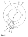
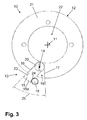
- the device 10 initially has an annular base element 12, which is mounted about an axis of rotation 11.
- the base member 12 consists of an annular body 21, on or on which an object to be rotated (not shown) can be attached.
- the annular body 21 surrounds an annular opening 22, in the center of which the axis of rotation 11 is located. As soon as the base element 12 is rotated about the axis of rotation 11, the object to be rotated is also rotated in the same way.
- the device 10 has a rotation angle limiting device 13.
- This device 13 consists of a number of components.
- the device 13 has an angular recess 19, which is formed in the annular body 21 of the base member 12.
- the angular recess 19 is bounded by two legs 16, 17, each forming a stop for a pivot stop 15.
- the angular recess 19 is designed such that, as viewed from the axis of rotation 11, it widens toward the outer edge of the annular body 21, namely around an angle 25 enclosed by the angled recess (FIG. FIG. 3 ).
- pivot stop 15 is provided, which is fixed by a screw 20 pivotally about the pivot axis 14 on the base member 12.
- the pivot stop 15 is in the form of a quadrangular profile, with part of the pivot stop 15 extending beyond the outer edge of the base member 12.
- the pivot stop 15 cooperates with a counter-stop 18 which, for example, can be arranged fixedly on a housing (not shown).
- stop portions 23, 24 are provided for the counter-stop, which are adapted to the contour of the counter-stop 18.
- FIG. 2 a situation is shown that corresponds to a 0 degree stop.
- FIG. 3 a situation is shown that corresponds to a 360 degree stop.
- the design of the device 13 for limiting the rotation angle can ensure that the physical width of the pivot stop 15 can be compensated, so that the rotation of the base element 12 can be limited to a full 360 degrees.
- the main difference between in the FIGS. 1 to 3 illustrated device 10 and the device 10 according to FIG. 4 is that the pivot stop 15 in FIG. 4 otherwise attached to the base member 12.
- the pivot stop 15 is disposed on the base member 12 such that the pivot axis 14 of the pivot stop 15, from the free end 15 a (see FIG. 3 ) of the pivot stop 15 from, in front of the axis of rotation 11 of the base member 12 is located.
- the pivot axis 14 of the pivot stop 15 seen from the free end 15a, behind the axis of rotation 11 of the base member 12th
- the device 10 for limiting the rotation angle has two angular recesses 19, 19 a (in the FIGS. 1 to 3 only an angular recess 19 is provided), the legs of each corresponding stops 16, 16a and 17, 17a to limit the pivotal movement of the pivot stop 15 form.
- the pivot stop 15 extends over the base element 12, and in particular via the annular opening 22 and the axis of rotation 11.
- the advantage of such a configuration is that the angular recess 19, the provided in the vicinity of the counter-stop 18 can be made larger.
- the region of the pivot stop 15, which extends beyond the outer boundary of the base element 12, can also be made larger. With a like in FIG. 4 illustrated device can thus be realized in an advantageous manner, a rotation angle limit for angles greater than 360 degrees.
Landscapes
- Physics & Mathematics (AREA)
- General Physics & Mathematics (AREA)
- Optics & Photonics (AREA)
- Chemical & Material Sciences (AREA)
- Analytical Chemistry (AREA)
- Health & Medical Sciences (AREA)
- General Health & Medical Sciences (AREA)
- Surgery (AREA)
- Microscoopes, Condenser (AREA)
- Telescopes (AREA)
Applications Claiming Priority (1)
| Application Number | Priority Date | Filing Date | Title |
|---|---|---|---|
| DE102007043845A DE102007043845A1 (de) | 2007-09-14 | 2007-09-14 | Vorrichtung zur Drehwinkelbegrenzung eines drehbar gelagerten Objekts sowie optische Beobachtungseinrichtung |
Publications (3)
| Publication Number | Publication Date |
|---|---|
| EP2037302A2 true EP2037302A2 (fr) | 2009-03-18 |
| EP2037302A3 EP2037302A3 (fr) | 2010-11-10 |
| EP2037302B1 EP2037302B1 (fr) | 2014-05-21 |
Family
ID=40019066
Family Applications (1)
| Application Number | Title | Priority Date | Filing Date |
|---|---|---|---|
| EP08163250.7A Not-in-force EP2037302B1 (fr) | 2007-09-14 | 2008-08-29 | Dispositif de limitation de l'angle de rotation d'un objet installé de manière rotative et dispositif d'observation optique |
Country Status (4)
| Country | Link |
|---|---|
| US (1) | US20090087252A1 (fr) |
| EP (1) | EP2037302B1 (fr) |
| JP (1) | JP2009068714A (fr) |
| DE (1) | DE102007043845A1 (fr) |
Families Citing this family (1)
| Publication number | Priority date | Publication date | Assignee | Title |
|---|---|---|---|---|
| US11294414B2 (en) | 2018-04-05 | 2022-04-05 | Medos International Sàrl | Surgical instruments with rotation stop devices |
Citations (3)
| Publication number | Priority date | Publication date | Assignee | Title |
|---|---|---|---|---|
| DE2346327A1 (de) | 1973-09-14 | 1975-03-27 | Eckardt Ag J | Messgeraet, insbesondere drehwinkelgeber |
| DD227202A1 (de) | 1984-10-05 | 1985-09-11 | Koepenick Funkwerk Veb | Vorrichtung zur drehwinkelbegrenzung fuer mechanische und elektrische drehschalter |
| DE10338498A1 (de) | 2002-05-03 | 2005-03-17 | Carl Zeiss | Gelenkanordnung |
Family Cites Families (8)
| Publication number | Priority date | Publication date | Assignee | Title |
|---|---|---|---|---|
| US2960913A (en) * | 1957-03-19 | 1960-11-22 | Univ California | Microscope mechanical stage for rotating objects such as film plates and the like about the optical axis of a microscope |
| US3615068A (en) * | 1969-07-14 | 1971-10-26 | Ardel Instr Co Inc | Precision rotary table |
| JP3104385B2 (ja) * | 1992-03-05 | 2000-10-30 | 株式会社ニコン | 測量機の粗微動装置 |
| JPH08194162A (ja) * | 1995-01-17 | 1996-07-30 | Nikon Corp | ステージの駆動装置 |
| US6483336B1 (en) * | 2000-05-03 | 2002-11-19 | Cascade Microtech, Inc. | Indexing rotatable chuck for a probe station |
| DE10300620B4 (de) * | 2002-05-18 | 2017-04-13 | Carl Zeiss Meditec Ag | Trägervorrichtung für ein medizinisch-optisches Gerät |
| CN100368854C (zh) * | 2003-09-19 | 2008-02-13 | 苏州信达光电科技有限公司 | 可改变观测角度的转角镜 |
| DE102004025590B4 (de) * | 2004-05-25 | 2010-02-25 | Lre Technology Partner Gmbh | Mechanischer Drehbereichsbegrenzer zum Begrenzen des Drehwinkels einer Welle |
-
2007
- 2007-09-14 DE DE102007043845A patent/DE102007043845A1/de not_active Ceased
-
2008
- 2008-08-29 EP EP08163250.7A patent/EP2037302B1/fr not_active Not-in-force
- 2008-09-15 US US12/283,744 patent/US20090087252A1/en not_active Abandoned
- 2008-09-16 JP JP2008236293A patent/JP2009068714A/ja active Pending
Patent Citations (3)
| Publication number | Priority date | Publication date | Assignee | Title |
|---|---|---|---|---|
| DE2346327A1 (de) | 1973-09-14 | 1975-03-27 | Eckardt Ag J | Messgeraet, insbesondere drehwinkelgeber |
| DD227202A1 (de) | 1984-10-05 | 1985-09-11 | Koepenick Funkwerk Veb | Vorrichtung zur drehwinkelbegrenzung fuer mechanische und elektrische drehschalter |
| DE10338498A1 (de) | 2002-05-03 | 2005-03-17 | Carl Zeiss | Gelenkanordnung |
Also Published As
| Publication number | Publication date |
|---|---|
| US20090087252A1 (en) | 2009-04-02 |
| DE102007043845A1 (de) | 2009-04-02 |
| JP2009068714A (ja) | 2009-04-02 |
| EP2037302A3 (fr) | 2010-11-10 |
| EP2037302B1 (fr) | 2014-05-21 |
Similar Documents
| Publication | Publication Date | Title |
|---|---|---|
| EP2092850B1 (fr) | Armature pour une armoire de coin | |
| EP3479776B1 (fr) | Dispositif de rétraction chirurgicale | |
| EP3003893A2 (fr) | Fermeture à genouillère | |
| EP2598355A1 (fr) | Expulseur d'air | |
| DE2556459A1 (de) | Schwenkvorrichtung fuer tueren | |
| DE102010004739A1 (de) | Vorrichtung zum Klemmen von Werkstücken auf einer Basis | |
| DE102013014966A1 (de) | Lenksäule für ein Fahrzeug | |
| EP2995824B1 (fr) | Dispositif d'ajustement de la position d'un premier composant mobile par rapport a un second composant fixe | |
| DE102012023295A1 (de) | Gartenschere | |
| DE202010003833U1 (de) | Möbelscharnier | |
| EP2499999A1 (fr) | Implant vertébral avec anneaux | |
| EP3815937B1 (fr) | Crochet d'attelage | |
| WO2018236324A2 (fr) | Dispositif de retenue pour façade de tiroir | |
| EP2037302B1 (fr) | Dispositif de limitation de l'angle de rotation d'un objet installé de manière rotative et dispositif d'observation optique | |
| EP1126114B1 (fr) | Charnière réglable | |
| DE102006005572B4 (de) | Stanzvorrichtung | |
| DE102010025978A1 (de) | Stativkopf-Anordnung | |
| EP0525507A2 (fr) | Dispositif de réglage d'un actionneur pour régler la cylindrée d'un machine hydrostatique | |
| EP1887151B1 (fr) | Support angulaire | |
| DE19904620B4 (de) | Einrastvorrichtung mit Rückstellfunktion für einen Blinkerschalter | |
| DE3823537C1 (fr) | ||
| DE102006029164B3 (de) | Kotflügelanordnung zur Abdeckung eines Fahrzeugrades | |
| DE3325763C2 (fr) | ||
| EP1870914A2 (fr) | Interrupteur de fin de course doté d'un élément de commutation | |
| DE102016115267B4 (de) | Vorrichtung zum Einstellen einer Rückenlehnenneigung und Verfahren zur Montage der Vorrichtung |
Legal Events
| Date | Code | Title | Description |
|---|---|---|---|
| PUAI | Public reference made under article 153(3) epc to a published international application that has entered the european phase |
Free format text: ORIGINAL CODE: 0009012 |
|
| AK | Designated contracting states |
Kind code of ref document: A2 Designated state(s): AT BE BG CH CY CZ DE DK EE ES FI FR GB GR HR HU IE IS IT LI LT LU LV MC MT NL NO PL PT RO SE SI SK TR |
|
| AX | Request for extension of the european patent |
Extension state: AL BA MK RS |
|
| PUAL | Search report despatched |
Free format text: ORIGINAL CODE: 0009013 |
|
| AK | Designated contracting states |
Kind code of ref document: A3 Designated state(s): AT BE BG CH CY CZ DE DK EE ES FI FR GB GR HR HU IE IS IT LI LT LU LV MC MT NL NO PL PT RO SE SI SK TR |
|
| AX | Request for extension of the european patent |
Extension state: AL BA MK RS |
|
| RIC1 | Information provided on ipc code assigned before grant |
Ipc: G02B 7/00 20060101AFI20081201BHEP Ipc: G02B 21/24 20060101ALI20101007BHEP Ipc: G02B 21/00 20060101ALI20101007BHEP |
|
| 17P | Request for examination filed |
Effective date: 20110405 |
|
| AKX | Designation fees paid |
Designated state(s): AT BE BG CH CY CZ DE DK EE ES FI FR GB GR HR HU IE IS IT LI LT LU LV MC MT NL NO PL PT RO SE SI SK TR |
|
| RAP1 | Party data changed (applicant data changed or rights of an application transferred) |
Owner name: CARL ZEISS MEDITEC AG |
|
| GRAP | Despatch of communication of intention to grant a patent |
Free format text: ORIGINAL CODE: EPIDOSNIGR1 |
|
| INTG | Intention to grant announced |
Effective date: 20130809 |
|
| GRAP | Despatch of communication of intention to grant a patent |
Free format text: ORIGINAL CODE: EPIDOSNIGR1 |
|
| INTG | Intention to grant announced |
Effective date: 20131212 |
|
| GRAS | Grant fee paid |
Free format text: ORIGINAL CODE: EPIDOSNIGR3 |
|
| GRAA | (expected) grant |
Free format text: ORIGINAL CODE: 0009210 |
|
| AK | Designated contracting states |
Kind code of ref document: B1 Designated state(s): AT BE BG CH CY CZ DE DK EE ES FI FR GB GR HR HU IE IS IT LI LT LU LV MC MT NL NO PL PT RO SE SI SK TR |
|
| REG | Reference to a national code |
Ref country code: GB Ref legal event code: FG4D Free format text: NOT ENGLISH |
|
| REG | Reference to a national code |
Ref country code: CH Ref legal event code: EP |
|
| REG | Reference to a national code |
Ref country code: AT Ref legal event code: REF Ref document number: 669872 Country of ref document: AT Kind code of ref document: T Effective date: 20140615 |
|
| REG | Reference to a national code |
Ref country code: IE Ref legal event code: FG4D Free format text: LANGUAGE OF EP DOCUMENT: GERMAN |
|
| REG | Reference to a national code |
Ref country code: DE Ref legal event code: R096 Ref document number: 502008011791 Country of ref document: DE Effective date: 20140626 |
|
| REG | Reference to a national code |
Ref country code: NL Ref legal event code: VDEP Effective date: 20140521 |
|
| REG | Reference to a national code |
Ref country code: LT Ref legal event code: MG4D |
|
| PG25 | Lapsed in a contracting state [announced via postgrant information from national office to epo] |
Ref country code: GR Free format text: LAPSE BECAUSE OF FAILURE TO SUBMIT A TRANSLATION OF THE DESCRIPTION OR TO PAY THE FEE WITHIN THE PRESCRIBED TIME-LIMIT Effective date: 20140822 Ref country code: FI Free format text: LAPSE BECAUSE OF FAILURE TO SUBMIT A TRANSLATION OF THE DESCRIPTION OR TO PAY THE FEE WITHIN THE PRESCRIBED TIME-LIMIT Effective date: 20140521 Ref country code: LT Free format text: LAPSE BECAUSE OF FAILURE TO SUBMIT A TRANSLATION OF THE DESCRIPTION OR TO PAY THE FEE WITHIN THE PRESCRIBED TIME-LIMIT Effective date: 20140521 Ref country code: IS Free format text: LAPSE BECAUSE OF FAILURE TO SUBMIT A TRANSLATION OF THE DESCRIPTION OR TO PAY THE FEE WITHIN THE PRESCRIBED TIME-LIMIT Effective date: 20140921 Ref country code: NO Free format text: LAPSE BECAUSE OF FAILURE TO SUBMIT A TRANSLATION OF THE DESCRIPTION OR TO PAY THE FEE WITHIN THE PRESCRIBED TIME-LIMIT Effective date: 20140821 |
|
| PG25 | Lapsed in a contracting state [announced via postgrant information from national office to epo] |
Ref country code: SE Free format text: LAPSE BECAUSE OF FAILURE TO SUBMIT A TRANSLATION OF THE DESCRIPTION OR TO PAY THE FEE WITHIN THE PRESCRIBED TIME-LIMIT Effective date: 20140521 Ref country code: ES Free format text: LAPSE BECAUSE OF FAILURE TO SUBMIT A TRANSLATION OF THE DESCRIPTION OR TO PAY THE FEE WITHIN THE PRESCRIBED TIME-LIMIT Effective date: 20140521 Ref country code: PL Free format text: LAPSE BECAUSE OF FAILURE TO SUBMIT A TRANSLATION OF THE DESCRIPTION OR TO PAY THE FEE WITHIN THE PRESCRIBED TIME-LIMIT Effective date: 20140521 Ref country code: LV Free format text: LAPSE BECAUSE OF FAILURE TO SUBMIT A TRANSLATION OF THE DESCRIPTION OR TO PAY THE FEE WITHIN THE PRESCRIBED TIME-LIMIT Effective date: 20140521 Ref country code: HR Free format text: LAPSE BECAUSE OF FAILURE TO SUBMIT A TRANSLATION OF THE DESCRIPTION OR TO PAY THE FEE WITHIN THE PRESCRIBED TIME-LIMIT Effective date: 20140521 |
|
| PG25 | Lapsed in a contracting state [announced via postgrant information from national office to epo] |
Ref country code: PT Free format text: LAPSE BECAUSE OF FAILURE TO SUBMIT A TRANSLATION OF THE DESCRIPTION OR TO PAY THE FEE WITHIN THE PRESCRIBED TIME-LIMIT Effective date: 20140922 |
|
| PG25 | Lapsed in a contracting state [announced via postgrant information from national office to epo] |
Ref country code: SK Free format text: LAPSE BECAUSE OF FAILURE TO SUBMIT A TRANSLATION OF THE DESCRIPTION OR TO PAY THE FEE WITHIN THE PRESCRIBED TIME-LIMIT Effective date: 20140521 Ref country code: RO Free format text: LAPSE BECAUSE OF FAILURE TO SUBMIT A TRANSLATION OF THE DESCRIPTION OR TO PAY THE FEE WITHIN THE PRESCRIBED TIME-LIMIT Effective date: 20140521 Ref country code: DK Free format text: LAPSE BECAUSE OF FAILURE TO SUBMIT A TRANSLATION OF THE DESCRIPTION OR TO PAY THE FEE WITHIN THE PRESCRIBED TIME-LIMIT Effective date: 20140521 Ref country code: EE Free format text: LAPSE BECAUSE OF FAILURE TO SUBMIT A TRANSLATION OF THE DESCRIPTION OR TO PAY THE FEE WITHIN THE PRESCRIBED TIME-LIMIT Effective date: 20140521 Ref country code: CZ Free format text: LAPSE BECAUSE OF FAILURE TO SUBMIT A TRANSLATION OF THE DESCRIPTION OR TO PAY THE FEE WITHIN THE PRESCRIBED TIME-LIMIT Effective date: 20140521 |
|
| REG | Reference to a national code |
Ref country code: DE Ref legal event code: R097 Ref document number: 502008011791 Country of ref document: DE |
|
| PG25 | Lapsed in a contracting state [announced via postgrant information from national office to epo] |
Ref country code: NL Free format text: LAPSE BECAUSE OF FAILURE TO SUBMIT A TRANSLATION OF THE DESCRIPTION OR TO PAY THE FEE WITHIN THE PRESCRIBED TIME-LIMIT Effective date: 20140521 |
|
| PLBE | No opposition filed within time limit |
Free format text: ORIGINAL CODE: 0009261 |
|
| STAA | Information on the status of an ep patent application or granted ep patent |
Free format text: STATUS: NO OPPOSITION FILED WITHIN TIME LIMIT |
|
| PG25 | Lapsed in a contracting state [announced via postgrant information from national office to epo] |
Ref country code: MC Free format text: LAPSE BECAUSE OF FAILURE TO SUBMIT A TRANSLATION OF THE DESCRIPTION OR TO PAY THE FEE WITHIN THE PRESCRIBED TIME-LIMIT Effective date: 20140521 Ref country code: LU Free format text: LAPSE BECAUSE OF FAILURE TO SUBMIT A TRANSLATION OF THE DESCRIPTION OR TO PAY THE FEE WITHIN THE PRESCRIBED TIME-LIMIT Effective date: 20140829 |
|
| REG | Reference to a national code |
Ref country code: CH Ref legal event code: PL |
|
| 26N | No opposition filed |
Effective date: 20150224 |
|
| GBPC | Gb: european patent ceased through non-payment of renewal fee |
Effective date: 20140829 |
|
| PG25 | Lapsed in a contracting state [announced via postgrant information from national office to epo] |
Ref country code: IT Free format text: LAPSE BECAUSE OF FAILURE TO SUBMIT A TRANSLATION OF THE DESCRIPTION OR TO PAY THE FEE WITHIN THE PRESCRIBED TIME-LIMIT Effective date: 20140521 Ref country code: BE Free format text: LAPSE BECAUSE OF NON-PAYMENT OF DUE FEES Effective date: 20140831 Ref country code: LI Free format text: LAPSE BECAUSE OF NON-PAYMENT OF DUE FEES Effective date: 20140831 Ref country code: CH Free format text: LAPSE BECAUSE OF NON-PAYMENT OF DUE FEES Effective date: 20140831 |
|
| REG | Reference to a national code |
Ref country code: IE Ref legal event code: MM4A |
|
| REG | Reference to a national code |
Ref country code: FR Ref legal event code: ST Effective date: 20150430 |
|
| REG | Reference to a national code |
Ref country code: DE Ref legal event code: R097 Ref document number: 502008011791 Country of ref document: DE Effective date: 20150224 |
|
| PG25 | Lapsed in a contracting state [announced via postgrant information from national office to epo] |
Ref country code: GB Free format text: LAPSE BECAUSE OF NON-PAYMENT OF DUE FEES Effective date: 20140829 Ref country code: SI Free format text: LAPSE BECAUSE OF FAILURE TO SUBMIT A TRANSLATION OF THE DESCRIPTION OR TO PAY THE FEE WITHIN THE PRESCRIBED TIME-LIMIT Effective date: 20140521 |
|
| PG25 | Lapsed in a contracting state [announced via postgrant information from national office to epo] |
Ref country code: IE Free format text: LAPSE BECAUSE OF NON-PAYMENT OF DUE FEES Effective date: 20140829 Ref country code: FR Free format text: LAPSE BECAUSE OF NON-PAYMENT OF DUE FEES Effective date: 20140901 |
|
| REG | Reference to a national code |
Ref country code: AT Ref legal event code: MM01 Ref document number: 669872 Country of ref document: AT Kind code of ref document: T Effective date: 20140829 |
|
| PG25 | Lapsed in a contracting state [announced via postgrant information from national office to epo] |
Ref country code: AT Free format text: LAPSE BECAUSE OF NON-PAYMENT OF DUE FEES Effective date: 20140829 |
|
| PG25 | Lapsed in a contracting state [announced via postgrant information from national office to epo] |
Ref country code: BG Free format text: LAPSE BECAUSE OF FAILURE TO SUBMIT A TRANSLATION OF THE DESCRIPTION OR TO PAY THE FEE WITHIN THE PRESCRIBED TIME-LIMIT Effective date: 20140521 |
|
| PG25 | Lapsed in a contracting state [announced via postgrant information from national office to epo] |
Ref country code: CY Free format text: LAPSE BECAUSE OF FAILURE TO SUBMIT A TRANSLATION OF THE DESCRIPTION OR TO PAY THE FEE WITHIN THE PRESCRIBED TIME-LIMIT Effective date: 20140521 Ref country code: MT Free format text: LAPSE BECAUSE OF FAILURE TO SUBMIT A TRANSLATION OF THE DESCRIPTION OR TO PAY THE FEE WITHIN THE PRESCRIBED TIME-LIMIT Effective date: 20140521 |
|
| PG25 | Lapsed in a contracting state [announced via postgrant information from national office to epo] |
Ref country code: TR Free format text: LAPSE BECAUSE OF FAILURE TO SUBMIT A TRANSLATION OF THE DESCRIPTION OR TO PAY THE FEE WITHIN THE PRESCRIBED TIME-LIMIT Effective date: 20140521 Ref country code: HU Free format text: LAPSE BECAUSE OF FAILURE TO SUBMIT A TRANSLATION OF THE DESCRIPTION OR TO PAY THE FEE WITHIN THE PRESCRIBED TIME-LIMIT; INVALID AB INITIO Effective date: 20080829 |
|
| REG | Reference to a national code |
Ref country code: DE Ref legal event code: R082 Ref document number: 502008011791 Country of ref document: DE Representative=s name: MUELLER, THOMAS, DIPL.-ING., DE |
|
| PGFP | Annual fee paid to national office [announced via postgrant information from national office to epo] |
Ref country code: DE Payment date: 20220727 Year of fee payment: 15 |
|
| REG | Reference to a national code |
Ref country code: DE Ref legal event code: R119 Ref document number: 502008011791 Country of ref document: DE |
|
| PG25 | Lapsed in a contracting state [announced via postgrant information from national office to epo] |
Ref country code: DE Free format text: LAPSE BECAUSE OF NON-PAYMENT OF DUE FEES Effective date: 20240301 |