EP2037318A1 - Affichage a cristaux liquides et panneau de commande d'angle de champ - Google Patents
Affichage a cristaux liquides et panneau de commande d'angle de champ Download PDFInfo
- Publication number
- EP2037318A1 EP2037318A1 EP07739245A EP07739245A EP2037318A1 EP 2037318 A1 EP2037318 A1 EP 2037318A1 EP 07739245 A EP07739245 A EP 07739245A EP 07739245 A EP07739245 A EP 07739245A EP 2037318 A1 EP2037318 A1 EP 2037318A1
- Authority
- EP
- European Patent Office
- Prior art keywords
- viewing angle
- liquid crystal
- viewpoint
- control panel
- plate
- Prior art date
- Legal status (The legal status is an assumption and is not a legal conclusion. Google has not performed a legal analysis and makes no representation as to the accuracy of the status listed.)
- Withdrawn
Links
Images




Classifications
-
- G—PHYSICS
- G02—OPTICS
- G02F—OPTICAL DEVICES OR ARRANGEMENTS FOR THE CONTROL OF LIGHT BY MODIFICATION OF THE OPTICAL PROPERTIES OF THE MEDIA OF THE ELEMENTS INVOLVED THEREIN; NON-LINEAR OPTICS; FREQUENCY-CHANGING OF LIGHT; OPTICAL LOGIC ELEMENTS; OPTICAL ANALOGUE/DIGITAL CONVERTERS
- G02F1/00—Devices or arrangements for the control of the intensity, colour, phase, polarisation or direction of light arriving from an independent light source, e.g. switching, gating or modulating; Non-linear optics
- G02F1/01—Devices or arrangements for the control of the intensity, colour, phase, polarisation or direction of light arriving from an independent light source, e.g. switching, gating or modulating; Non-linear optics for the control of the intensity, phase, polarisation or colour
- G02F1/13—Devices or arrangements for the control of the intensity, colour, phase, polarisation or direction of light arriving from an independent light source, e.g. switching, gating or modulating; Non-linear optics for the control of the intensity, phase, polarisation or colour based on liquid crystals, e.g. single liquid crystal display cells
- G02F1/133—Constructional arrangements; Operation of liquid crystal cells; Circuit arrangements
- G02F1/1333—Constructional arrangements; Manufacturing methods
- G02F1/1335—Structural association of cells with optical devices, e.g. polarisers or reflectors
- G02F1/13363—Birefringent elements, e.g. for optical compensation
-
- G—PHYSICS
- G02—OPTICS
- G02F—OPTICAL DEVICES OR ARRANGEMENTS FOR THE CONTROL OF LIGHT BY MODIFICATION OF THE OPTICAL PROPERTIES OF THE MEDIA OF THE ELEMENTS INVOLVED THEREIN; NON-LINEAR OPTICS; FREQUENCY-CHANGING OF LIGHT; OPTICAL LOGIC ELEMENTS; OPTICAL ANALOGUE/DIGITAL CONVERTERS
- G02F1/00—Devices or arrangements for the control of the intensity, colour, phase, polarisation or direction of light arriving from an independent light source, e.g. switching, gating or modulating; Non-linear optics
- G02F1/01—Devices or arrangements for the control of the intensity, colour, phase, polarisation or direction of light arriving from an independent light source, e.g. switching, gating or modulating; Non-linear optics for the control of the intensity, phase, polarisation or colour
- G02F1/13—Devices or arrangements for the control of the intensity, colour, phase, polarisation or direction of light arriving from an independent light source, e.g. switching, gating or modulating; Non-linear optics for the control of the intensity, phase, polarisation or colour based on liquid crystals, e.g. single liquid crystal display cells
- G02F1/133—Constructional arrangements; Operation of liquid crystal cells; Circuit arrangements
- G02F1/1333—Constructional arrangements; Manufacturing methods
- G02F1/1335—Structural association of cells with optical devices, e.g. polarisers or reflectors
-
- C—CHEMISTRY; METALLURGY
- C08—ORGANIC MACROMOLECULAR COMPOUNDS; THEIR PREPARATION OR CHEMICAL WORKING-UP; COMPOSITIONS BASED THEREON
- C08J—WORKING-UP; GENERAL PROCESSES OF COMPOUNDING; AFTER-TREATMENT NOT COVERED BY SUBCLASSES C08B, C08C, C08F, C08G or C08H
- C08J5/00—Manufacture of articles or shaped materials containing macromolecular substances
- C08J5/18—Manufacture of films or sheets
-
- G—PHYSICS
- G02—OPTICS
- G02F—OPTICAL DEVICES OR ARRANGEMENTS FOR THE CONTROL OF LIGHT BY MODIFICATION OF THE OPTICAL PROPERTIES OF THE MEDIA OF THE ELEMENTS INVOLVED THEREIN; NON-LINEAR OPTICS; FREQUENCY-CHANGING OF LIGHT; OPTICAL LOGIC ELEMENTS; OPTICAL ANALOGUE/DIGITAL CONVERTERS
- G02F1/00—Devices or arrangements for the control of the intensity, colour, phase, polarisation or direction of light arriving from an independent light source, e.g. switching, gating or modulating; Non-linear optics
- G02F1/01—Devices or arrangements for the control of the intensity, colour, phase, polarisation or direction of light arriving from an independent light source, e.g. switching, gating or modulating; Non-linear optics for the control of the intensity, phase, polarisation or colour
- G02F1/13—Devices or arrangements for the control of the intensity, colour, phase, polarisation or direction of light arriving from an independent light source, e.g. switching, gating or modulating; Non-linear optics for the control of the intensity, phase, polarisation or colour based on liquid crystals, e.g. single liquid crystal display cells
- G02F1/1323—Arrangements for providing a switchable viewing angle
-
- G—PHYSICS
- G02—OPTICS
- G02F—OPTICAL DEVICES OR ARRANGEMENTS FOR THE CONTROL OF LIGHT BY MODIFICATION OF THE OPTICAL PROPERTIES OF THE MEDIA OF THE ELEMENTS INVOLVED THEREIN; NON-LINEAR OPTICS; FREQUENCY-CHANGING OF LIGHT; OPTICAL LOGIC ELEMENTS; OPTICAL ANALOGUE/DIGITAL CONVERTERS
- G02F1/00—Devices or arrangements for the control of the intensity, colour, phase, polarisation or direction of light arriving from an independent light source, e.g. switching, gating or modulating; Non-linear optics
- G02F1/01—Devices or arrangements for the control of the intensity, colour, phase, polarisation or direction of light arriving from an independent light source, e.g. switching, gating or modulating; Non-linear optics for the control of the intensity, phase, polarisation or colour
- G02F1/13—Devices or arrangements for the control of the intensity, colour, phase, polarisation or direction of light arriving from an independent light source, e.g. switching, gating or modulating; Non-linear optics for the control of the intensity, phase, polarisation or colour based on liquid crystals, e.g. single liquid crystal display cells
- G02F1/133—Constructional arrangements; Operation of liquid crystal cells; Circuit arrangements
- G02F1/1333—Constructional arrangements; Manufacturing methods
- G02F1/1335—Structural association of cells with optical devices, e.g. polarisers or reflectors
- G02F1/13363—Birefringent elements, e.g. for optical compensation
- G02F1/133634—Birefringent elements, e.g. for optical compensation the refractive index Nz perpendicular to the element surface being different from in-plane refractive indices Nx and Ny, e.g. biaxial or with normal optical axis
-
- G—PHYSICS
- G02—OPTICS
- G02F—OPTICAL DEVICES OR ARRANGEMENTS FOR THE CONTROL OF LIGHT BY MODIFICATION OF THE OPTICAL PROPERTIES OF THE MEDIA OF THE ELEMENTS INVOLVED THEREIN; NON-LINEAR OPTICS; FREQUENCY-CHANGING OF LIGHT; OPTICAL LOGIC ELEMENTS; OPTICAL ANALOGUE/DIGITAL CONVERTERS
- G02F1/00—Devices or arrangements for the control of the intensity, colour, phase, polarisation or direction of light arriving from an independent light source, e.g. switching, gating or modulating; Non-linear optics
- G02F1/01—Devices or arrangements for the control of the intensity, colour, phase, polarisation or direction of light arriving from an independent light source, e.g. switching, gating or modulating; Non-linear optics for the control of the intensity, phase, polarisation or colour
- G02F1/13—Devices or arrangements for the control of the intensity, colour, phase, polarisation or direction of light arriving from an independent light source, e.g. switching, gating or modulating; Non-linear optics for the control of the intensity, phase, polarisation or colour based on liquid crystals, e.g. single liquid crystal display cells
- G02F1/133—Constructional arrangements; Operation of liquid crystal cells; Circuit arrangements
- G02F1/1333—Constructional arrangements; Manufacturing methods
- G02F1/1335—Structural association of cells with optical devices, e.g. polarisers or reflectors
- G02F1/13363—Birefringent elements, e.g. for optical compensation
- G02F1/133638—Waveplates, i.e. plates with a retardation value of lambda/n
-
- G—PHYSICS
- G02—OPTICS
- G02F—OPTICAL DEVICES OR ARRANGEMENTS FOR THE CONTROL OF LIGHT BY MODIFICATION OF THE OPTICAL PROPERTIES OF THE MEDIA OF THE ELEMENTS INVOLVED THEREIN; NON-LINEAR OPTICS; FREQUENCY-CHANGING OF LIGHT; OPTICAL LOGIC ELEMENTS; OPTICAL ANALOGUE/DIGITAL CONVERTERS
- G02F1/00—Devices or arrangements for the control of the intensity, colour, phase, polarisation or direction of light arriving from an independent light source, e.g. switching, gating or modulating; Non-linear optics
- G02F1/01—Devices or arrangements for the control of the intensity, colour, phase, polarisation or direction of light arriving from an independent light source, e.g. switching, gating or modulating; Non-linear optics for the control of the intensity, phase, polarisation or colour
- G02F1/13—Devices or arrangements for the control of the intensity, colour, phase, polarisation or direction of light arriving from an independent light source, e.g. switching, gating or modulating; Non-linear optics for the control of the intensity, phase, polarisation or colour based on liquid crystals, e.g. single liquid crystal display cells
- G02F1/133—Constructional arrangements; Operation of liquid crystal cells; Circuit arrangements
- G02F1/1333—Constructional arrangements; Manufacturing methods
- G02F1/1347—Arrangement of liquid crystal layers or cells in which the final condition of one light beam is achieved by the addition of the effects of two or more layers or cells
-
- G—PHYSICS
- G02—OPTICS
- G02F—OPTICAL DEVICES OR ARRANGEMENTS FOR THE CONTROL OF LIGHT BY MODIFICATION OF THE OPTICAL PROPERTIES OF THE MEDIA OF THE ELEMENTS INVOLVED THEREIN; NON-LINEAR OPTICS; FREQUENCY-CHANGING OF LIGHT; OPTICAL LOGIC ELEMENTS; OPTICAL ANALOGUE/DIGITAL CONVERTERS
- G02F2413/00—Indexing scheme related to G02F1/13363, i.e. to birefringent elements, e.g. for optical compensation, characterised by the number, position, orientation or value of the compensation plates
- G02F2413/04—Number of plates greater than or equal to 4
-
- G—PHYSICS
- G02—OPTICS
- G02F—OPTICAL DEVICES OR ARRANGEMENTS FOR THE CONTROL OF LIGHT BY MODIFICATION OF THE OPTICAL PROPERTIES OF THE MEDIA OF THE ELEMENTS INVOLVED THEREIN; NON-LINEAR OPTICS; FREQUENCY-CHANGING OF LIGHT; OPTICAL LOGIC ELEMENTS; OPTICAL ANALOGUE/DIGITAL CONVERTERS
- G02F2413/00—Indexing scheme related to G02F1/13363, i.e. to birefringent elements, e.g. for optical compensation, characterised by the number, position, orientation or value of the compensation plates
- G02F2413/08—Indexing scheme related to G02F1/13363, i.e. to birefringent elements, e.g. for optical compensation, characterised by the number, position, orientation or value of the compensation plates with a particular optical axis orientation
-
- G—PHYSICS
- G02—OPTICS
- G02F—OPTICAL DEVICES OR ARRANGEMENTS FOR THE CONTROL OF LIGHT BY MODIFICATION OF THE OPTICAL PROPERTIES OF THE MEDIA OF THE ELEMENTS INVOLVED THEREIN; NON-LINEAR OPTICS; FREQUENCY-CHANGING OF LIGHT; OPTICAL LOGIC ELEMENTS; OPTICAL ANALOGUE/DIGITAL CONVERTERS
- G02F2413/00—Indexing scheme related to G02F1/13363, i.e. to birefringent elements, e.g. for optical compensation, characterised by the number, position, orientation or value of the compensation plates
- G02F2413/12—Biaxial compensators
Definitions
- the present invention relates to a viewing angle control panel for switching over a viewing angle of a display panel between a wide viewing angle and a narrow viewing angle and a liquid crystal display device including the viewing angle control panel.
- a display device is required to have a viewing angle as wide as possible so that a clear image can be seen from any visual angle.
- the liquid crystal itself has viewing angle dependency. Therefore, various techniques have been developed in order to increase the width of the viewing angle.
- a display device in some environment, there is a case where it is preferable for a display device to have a narrow viewing angle so that only a user himself can see display contents.
- a notebook personal computer, PDA (Personal Data Assistant) or a mobile phone and the like are likely to be used in a place, such as a train and an airplane, where a large number of people can exist.
- a display device in view of protection of secrets and privacy, it is desirable that a display device has a narrow viewing angle so that others in the vicinity of the user cannot see display contents.
- Patent Document 1 discloses a technique in which a phase difference control device is provided in addition to a display device for displaying an image.
- the technique disclosed in Patent Document 1 enables a viewing angle characteristic to change by controlling a voltage applied to the phase difference control device.
- a chiral nematic liquid crystal, a homogeneous liquid crystal and a randomly oriented nematic liquid crystal are given as examples of a liquid crystal mode used in a phase difference control liquid crystal display device.
- Patent Document 2 and Patent Document 3 disclose an arrangement in which a viewing angle control liquid crystal panel is provided on a display liquid crystal panel, and these panels are sandwiched by two polarizing plates.
- a viewing angle is controlled by adjusting a voltage applied to the viewing angle control liquid crystal panel.
- a liquid crystal mode of the viewing angle control liquid crystal panel is a twisted nematic mode.
- Patent Document 4 discloses a display having a liquid crystal device, between a backlight and a display device.
- the liquid crystal device makes it possible to switch over between a first state and a second state, the first state providing a first viewing angle, the second state providing a second viewing angle which is narrower than the first viewing angle.
- the conventional Patent Document 1 describes that it is possible to switch over between a wide viewing angle and a narrow viewing angle by using the phase difference control liquid crystal display device. However, this does not produce a sufficient effect. For example, as shown in Fig. 16 , an equal contrast curve having a contrast ratio of 10:1 is shown in the Patent Document 1. In a narrow viewing angle mode, the contrast is surely low in a wide viewing angle direction. However, such a change cannot ensure privacy from other people.
- Patent Documents 2 through 4 also makes it possible to switch over between a wide viewing angle and a narrow viewing angle by changing a voltage applied to a viewing angle control liquid crystal panel and adjusting a contrast. However, this does not produce a sufficient effect.
- the present invention was accomplished in view of the above problems. It is an object of the present invention to provide a viewing angle control panel which allows an improvement of a blocking effect and to provide a liquid crystal display device including the same.
- a liquid crystal display device of the present invention includes a backlight, a liquid crystal display panel and a viewing angle control panel for switching a viewing angle of the liquid crystal display panel over between a first viewing angle and a second viewing angle which is within the first viewing angle and narrower than the first viewing angle, wherein: the viewing angle control panel includes a first polarizing plate, a liquid crystal layer and a second polarizing plate stacked in this order, the viewing angle control panel includes at least one phase difference plate at least one of between the first polarizing plate and the liquid crystal layer and between the second polarizing plate and the liquid crystal layer, when the viewing angle of the liquid crystal display panel is the first viewing angle, the liquid crystal display panel has a retardation value Re1 of n ⁇ /2- ⁇ /4 ⁇ Re1 ⁇ n ⁇ /2+ ⁇ /4 (n is an integer of 1 or more) at a white display portion, when the viewing angle of the liquid crystal display panel is the second viewing angle, the liquid crystal display panel has a retardation value Re2 of n ⁇ /2-
- the viewing angle is the second viewing angle which is narrower than the first viewing angle
- a liquid crystal display device having a larger blocking area i.e. having a narrower viewing angle range which can be seen
- This makes it possible to provide a liquid crystal display device in which display contents cannot be seen from directions except a specific direction, the liquid crystal display device having an excellent protection of privacy and security.
- the "white display portion” means an area where light is not blocked and display can be seen, and the “black display portion” means an area where light is blocked and display cannot be seen. Therefore, the "white display portion” can be termed “visible area”, and the “black display portion” can be termed “non-visible area”.
- the retardation value means a phase difference between individual components of light which passed through the viewing angle control panel (difference between a phase of light which moves in a delay phase axis plane and a phase of light which moves in an advance phase axis plane).
- the retardation value Re1 is n ⁇ /2 (n is an integer of 1 or more)
- the retardation value Re2 is n ⁇ /2 (n is an integer of 1 or more)
- the retardation value Re3 is n ⁇ (n is an integer of 1 or more). According to the above arrangement, it is possible to make a viewing angle narrower in the second viewing angle.
- retardation values at a first viewpoint and a fifth viewpoint are n ⁇ /2- ⁇ /4 through n ⁇ /2+ ⁇ /4 (n is an integer of 1 or more) in the second viewing angle
- retardation values at a second viewpoint, a third viewpoint and a fourth viewpoint are n ⁇ - ⁇ /4 through n ⁇ + ⁇ /4 (n is an integer of 1 or more)
- a polar angle ⁇ is an angle formed between a straight line drawn from a center of a surface of the viewing angle control panel to a viewpoint and a normal at the center of the surface of the
- the phase difference plate is provided at each of between the first polarizing plate and the liquid crystal layer and between the second polarizing plate and the liquid crystal layer.
- the plurality of phase difference plates are stacked at least one of between the first polarizing plate and the liquid crystal layer, and between the second polarizing plate and the liquid crystal layer, the phase difference plates stacked on each other preferably having different refractive indexes.
- the phase difference plate is selected from the group consisting of a ⁇ /4 plate, a negative C plate, and a two-axis phase difference plate having three main refractive indexes nx, ny and nz in x-axis, y-axis and z-axis directions, the x-axis, y-axis and z-axis crossing each other at right angles, and the refractive indexes nx, ny and nz satisfying nx>nz>ny and (nx-nz) /
- 0.1.
- the liquid crystal display device of the present invention it is preferable that at least the ⁇ /4 plate and the negative C plate are provided, as the phase difference plate, at least one of between the first polarizing plate and the liquid crystal layer, and between the second polarizing plate and the liquid crystal layer.
- the liquid crystal display device of the present invention includes, as the phase difference plate, the negative C plate, the ⁇ /4 plate and the two-axis phase difference plate, and at least one of between the first polarizing plate and the liquid crystal layer, and between the second polarizing plate and the liquid crystal layer, the negative C plate, the ⁇ /4 plate and the two-axis phase difference plate are stacked in this order from the liquid crystal layer side.
- polarizing transmission axes of the first polarizing plate and second polarizing plate constituting the viewing angle control panel cross each other at right angles. That is, in the viewing angle control panel, it is preferable that the polarizing transmission axes of the two polarizing plates disposed so as to face each other via the liquid crystal layer are disposed so as to cross each other at right angles.
- the wording that the polarizing transmission axes cross each other at right angles also means that the polarizing transmission axes cross each other at substantially right angles.
- the wording that the polarizing transmission axes cross each other at substantially right angles means that the polarizing transmission axes form an angle ranging from 80° to 100°.
- a viewing angle control panel of the present invention is a viewing angle control panel (i) disposed on at least one of a back surface and a front surface of a display device for displaying an image and (ii) configured to switch a viewing angle of the display device over between a first viewing angle and a second viewing angle which is within the first viewing angle and narrower than the first viewing angle, wherein: the viewing angle control panel includes a first polarizing plate, a liquid crystal layer and a second polarizing plate stacked in this order, the viewing angle control panel includes at least one phase difference plate at least one of between the first polarizing plate and the liquid crystal layer and between the second polarizing plate and the liquid crystal layer, when the viewing angle of the display device is the first viewing angle, the display device has a retardation value Re1 of n ⁇ /2- ⁇ /4 ⁇ Re1 ⁇ n ⁇ /2+ ⁇ /4 (n is an integer of 1 or more) at a white display portion, when the viewing angle of the display device is the second viewing angle, the display device has
- the viewing angle when the viewing angle is the second viewing angle which is narrower than the first viewing angle, it is possible to provide a liquid crystal display device having a larger blocking area (i.e. having a narrower viewing angle range which can be seen) than a conventional viewing angle control panel.
- the viewing angle control panel By disposing the viewing angle control panel on at least one of the back surface and the front surface of the display device, it is possible to provide a liquid crystal display device in which display contents cannot be seen from directions except a specific direction, the liquid crystal display device having an excellent protection of privacy and security.
- the "white display portion” means an area where light is not blocked and display can be seen, and the “black display portion” means an area where light is blocked and display cannot be seen. Therefore, the "white display portion” can be termed “visible area”, and the “black display portion” can be termed “non-visible area”.
- the retardation value means a phase difference between individual components of light which passed through the viewing angle control panel (difference between a phase of light which moves in a delay phase axis plane and a phase of light which moves in an advance phase axis plane).
- the retardation value Re1 is n ⁇ /2 (n is an integer of 1 or more)
- the retardation value Re2 is n ⁇ /2 (n is an integer of 1 or more)
- the retardation value Re3 is n ⁇ (n is an integer of 1 or more).
- a liquid crystal display device of the present invention can include constituent members which are not shown in the drawings referred in the present specification. Further, the drawings do not illustrate the members in actual dimension and in actual dimensional ratios.
- Fig. 1 is a cross-sectional view showing an outline of an arrangement of the liquid crystal display device 10.
- the liquid crystal display device 10 includes two liquid crystal panels, that is, a display liquid crystal panel 1 (liquid crystal display panel) as a display panel for displaying an image, and a viewing angle control panel 2 including a liquid crystal cell 21.
- the display liquid crystal panel 1 is transmission-type, and a backlight 3 is used as a light source.
- the viewing angle control panel 2 is provided between the backlight 3 and the display liquid crystal panel 1.
- the liquid crystal display device 10 can switch over a display status between two modes, that is, a wide viewing angle (first viewing angle) in which an area where an image of the display liquid crystal panel 1 can be seen is wide and a narrow viewing angle (second viewing angle) in which an area where an image of the display liquid crystal panel 1 can be seen is narrow.
- the narrow viewing angle is suitably used when an user wants to prevent others from seeing an image of the display liquid crystal panel 1
- the wide viewing angle is suitably used when used in a normal situation except this or when more than one person see an image of the display liquid crystal panel 1.
- the display liquid crystal panel 1 has liquid crystal cell 11 in which liquid crystal is sandwiched between a pair of light-transmitting substrates, and a liquid crystal panel upper polarizing plate 12 and a liquid crystal panel lower polarizing plate 13 respectively provided on a front surface and a rear surface of the liquid crystal cell 11.
- the liquid crystal cell 11 may have any liquid crystal mode and any cell structure.
- the display liquid crystal panel 1 may adopt any driving mode, too. That is, any liquid crystal panel which can display words, images or moving pictures can be used as the display liquid crystal panel 1. Therefore, a detailed structure of the display liquid crystal panel 1 is not shown in Fig. 1 , and is not explained herein.
- the display liquid crystal panel 1 may be a panel which can display a color image or may be a panel which can display only a monochromatic image.
- an arrangement of the backlight 3 is not limited, and any known backlight can be used. Therefore, a detailed structure of the backlight 3 is not shown in Fig. 1 , and is not explained, too.
- the viewing angle control panel 2 includes the liquid crystal cell 21 in which a liquid crystal layer is sandwiched between a pair of light-transmitting substrates 21a and 21b which are described below, two phase difference plates (upper phase difference plate 24 and lower phase difference plate 25) disposed so as to sandwich the liquid crystal cell 21, a control panel upper polarizing plate 22 (first polarizing plate) provided on top of the upper phase difference plate 24, that is, provided on a surface of the liquid crystal cell 21 nearer to the display liquid crystal panel 1, and a control panel lower polarizing plate 23 (second polarizing plate) provided on bottom of the lower phase difference plate 25, that is, provided on a surface of the liquid crystal cell 21 nearer to the backlight 3.
- the liquid crystal layer of the liquid crystal cell 21 is made of homogeneous aligned positive type nematic liquid crystal.
- the viewing angle control panel 2 includes the control panel lower polarizing plate 23, the liquid crystal cell 21 and the control panel upper polarizing plate 22 stacked in this order, the lower phase difference plate 25 is provided between the control panel lower polarizing plate 23 and the liquid crystal cell 21, and the upper phase difference plate 24 is provided between the control panel upper polarizing plate 22 and the liquid crystal cell 21.
- control panel upper polarizing plate 22 is treated with a diffusion treatment such as an AG treatment.
- control panel lower polarizing plate 23 is made of a so-called clear polarizing plate on which a surface treatment is not carried out.
- the control panel upper polarizing plate 22 are not necessarily needed and can be omitted. That is, at least one polarizing plate is needed between the viewing angle control panel 2 and the display liquid crystal panel 1. Therefore, it is possible to use the liquid crystal panel lower polarizing plate 13 of the display liquid crystal panel 1 to utilize it also as the control panel upper polarizing plate 22. In this case, the liquid crystal panel lower polarizing plate 13 corresponds to the polarizing plate of the present invention.
- Figs. 2 (a) and 2 (b) are schematic views mainly showing an arrangement of the viewing angle control panel 2, Fig. 2 (a) shows an orientation of liquid crystal molecules in a narrow viewing angle mode, and Fig. 2 (b) shows an orientation of liquid crystal molecules in a wide viewing angle mode.
- the liquid crystal cell 21 of the viewing angle control panel 2 includes the pair of light transmitting substrates 21a and 21b.
- a transparent electrode (not shown) is formed on a surface of each of the light transmitting substrates 21 a and 21 b by using, for example, ITO (Indium Tin Oxide).
- ITO Indium Tin Oxide
- the display liquid crystal panel 1 has an electrode structure necessary for display units because it is necessary to drive the liquid crystal on the basis of the display units such as pixel units or segment units.
- the viewing angle control panel 2 is not limited in terms of its electrode structure.
- the viewing angle control panel 2 may be arranged such that the transparent electrode is formed uniformly on whole of the light transmitting substrates 21a and 21b in order to perform switching uniformly on whole of a display surface.
- the viewing angle control panel 2 can have a different electrode structure.
- An alignment film (not shown) for aligning liquid crystal molecules 21c is formed on the transparent electrode.
- a rubbing treatment is carried out on the alignment film by using a known method.
- rubbing directions in the light transmitting substrates 21a and 21b are shown by the arrows Ra and Rb, respectively.
- the rubbing direction Ra of the alignment film of the light transmitting substrate 21a is parallel to and opposite to the rubbing direction Rb of the alignment film of the light transmitting substrate 21b.
- the liquid crystal cell 21 is a so-called parallel type cell having a twist angle 0 (no twist).
- liquid crystal injected into the liquid crystal cell 21 is homogeneous aligned liquid crystal. Therefore, when a voltage is not applied, the liquid crystal molecules 21 c of the liquid crystal cell 21 are oriented so that a long molecular axis is parallel to surfaces of the light transmitting substrates 21a and 21b.
- a retardation value d ⁇ n (d is the thickness of the cell and ⁇ n is a birefringent index) of the liquid crystal layer of the liquid crystal cell 21 is 350nm through 450nm.
- the liquid crystal molecules 21c oriented parallel to the surfaces of the substrates change their directions gradually in accordance with the magnitude of the applied voltage in a plane, as shown in Fig. 2 (a) , vertical to normal of the light transmitting substrates 21a and 21b and parallel to the rubbing directions Ra and Rb of the light transmitting substrate 21a.
- the applied voltage reaches a predetermined value
- the liquid crystal molecules 21c are oriented in such a manner that the long molecular axis is substantially vertical to the surfaces of the light transmitting substrates 21a and 21b, as shown in Fig. 2 (b) . That is, Fig.
- FIG. 2 (a) shows a state where the long molecular axis of the liquid crystal molecules 21c is slightly tilted to the normal of the light transmitting substrates 21a and 21b due to the applied voltage V L (for example, a voltage of approximately 2.5V through 3.5V). Further, Fig. 2 (b) shows a state where the long molecular axis of the liquid crystal molecules 21c is substantially vertical to the surfaces of the light transmitting substrates 21a and 21b due to the applied voltage V H (for example, a voltage of 5V or more).
- V L for example, a voltage of approximately 2.5V through 3.5V
- V H for example, a voltage of 5V or more
- the control panel lower polarizing plate 23 and the control panel upper polarizing plate 22 respectively provided below the liquid crystal cell 21 and above the liquid crystal cell 21 are disposed so that respective polarizing transmission axis X 23 and polarizing transmission axis X 22 cross each other at substantially the right angle.
- the polarizing transmission axis X 23 and the polarizing transmission axis X 22 cross each other at substantially the right angle (i.e. when an angle formed by the polarizing transmission axis X 23 and the polarizing transmission axis X 22 ranges from 80° to 100°), it is possible to obtain sufficient effects in viewing angle switching.
- the polarizing transmission axis X 22 of the control panel upper polarizing plate 22 has an inclination of 40° through 50° (preferably 45°) with respect to the rubbing direction R of the alignment film of the light transmitting substrate 21a.
- a principle of switching a viewing angle over between a wide viewing angle and a narrow viewing angle is explained by using the viewing angle control panel 2 having the above arrangement with reference to Fig. 3 and Figs. 4 (a) through 4 (c) in addition to Figs. 2 (a) and 2 (b) described above. That is, the viewing angle control panel 2 switches a viewing angle over between a wide viewing angle and a narrow viewing angle by switching a voltage applied to the liquid crystal cell 21.
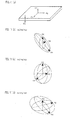
- a visual angle from a viewpoint to the viewing angle control panel 2 is indicated by an azimuth ⁇ and a polar angle ⁇ whose base point is the center of the control panel upper polarizing plate 22.
- Fig. 3 shows visual angles from three viewpoints P 1 through P 3 to the viewpoint control panel 2 arranged in the same direction as Figs. 2 (a) and 2 (b) .
- the azimuth ⁇ is a rotation angle of a line linking a foot of a perpendicular line drawn from a viewpoint to a plane including the surface of the control panel upper polarizing plate 22 and the center 22c of the control panel upper polarizing plate 22.
- the azimuth ⁇ is set to be 0° in a direction of viewpoint P 1 , and increases clockwise when viewed from the upper side of the normal direction of the control panel upper polarizing plate 22.
- an azimuth ⁇ 2 of the viewpoint P 2 is 90°
- an azimuth ⁇ 3 of the viewpoint P 3 is 180°.
- the polar angle ⁇ is an angle formed by a straight line drawn from the center 22c of the control panel upper polarizing plate 22 to the viewpoint and the normal of the control panel upper polarizing plate 22.
- a shorter axis side of the liquid crystal molecules 21c faces a visual angle direction.
- L 1 through L 8 are equipotential lines showing distribution of visual angles having luminance of 50cd/m 2 , 100cd/m 2 , 150cd/m 2 , 200cd/m 2 , 250cd/m 2 , 300cd/m 2 , 350cd/m 2 and 400cd/m 2 .
- the long molecular axis of the liquid crystal molecules 21c are slightly tilted to each of the polarizing transmission axis X 22 of the control panel upper polarizing plate 22 and the control panel lower polarizing plate 23.
- a linearly polarized light emitted from the backlight 3, transmitted through the control panel lower polarizing plate 23 and entered into the liquid crystal cell 21 is given a small birefringence by the liquid crystal molecules 21c, but blocked by the control panel upper polarizing plate 22.
- the long molecular axis of the liquid crystal molecules 21c is tilted at 45° with respect to each of the polarizing transmission axis X 22 of the control panel upper polarizing plate 22 and the polarizing transmission axis X 23 of the control panel lower polarizing plate 23, and a longer axis side of the liquid crystal molecules 21c faces the visual angle direction.
- a linearly polarized light emitted from the backlight 3, transmitted through the control panel lower polarizing plate 23 and entered into the liquid crystal cell 21 is given a birefringence by the liquid crystal molecules 21c, and transmits the control panel upper polarizing plate 22 after its polarization direction is rotated so as to equal with the polarizing transmission axis X 22 of the control panel upper polarizing plate 22. Therefore, as for the visual angle from the viewpoint P 3 , an excellent display can be obtained.
- L 1 through L 8 are equipotential lines showing distribution of visual angles having luminance of 130cd/m 2 , 240cd/m 2 , 350cd/m 2 , 460cd/m 2 , 570cd/m 2 , 680cd/m 2 , 790cd/m 2 and 900cd/m 2 .
- liquid crystal display device 10 of the present embodiment it is possible to switch a display status of the liquid crystal display device 10 between a wide viewing angle and a narrow viewing angle by switching a voltage applied to the liquid crystal cell 21 of the viewing angle control panel 2 between two levels of the applied voltage V H and the applied voltage V L .
- phase difference plate 24 and lower phase difference plate 25 are respectively provided between the liquid crystal cell 21 and the polarizing plate (upper polarizing plate 22 and lower polarizing plate 23).
- a phase difference plate be provided at least one of between the control panel upper polarizing plate 22 and the liquid crystal cell 21 and between the control panel lower polarizing plate 23 and the liquid crystal cell 21.
- Fig. 7 is a schematic view showing an arrangement of a viewing angle control panel 2' where one phase difference plate is provided.
- the viewing angle control panel 2' further includes the phase difference plate 24a between the light transmitting substrate 21a of the liquid crystal cell 21 and the control panel upper polarizing plate 22.
- a display state is switched to a narrow viewing angle by applying the voltage V L to the liquid crystal cell 21
- a linearly polarized light which was emitted from the backlight 3 and transmitted through the control panel lower polarizing plate 23 becomes an elliptically polarized light when viewed from a visual angle except the vicinity of the azimuth 180° shown in Fig. 3 (e.g.
- the phase difference plate 24 is provided for optical compensation of the elliptically polarized light. That is, in the narrow viewing angle mode, the phase difference plate 24a is a phase difference plate which generates an elliptically polarized light which offsets an elliptically polarized light generated in the liquid crystal layer of the liquid crystal cell 21.
- Nx is a component vertical to the polarizing transmission axis X 22 of the control panel upper polarizing plate 22
- N Y is a component parallel to the polarizing transmission axis X 22 of the control panel upper polarizing plate 22
- Nz is a component parallel to the normal of the control panel upper polarizing plate 22.
- Fig. 8 (a) shows a refractive index ellipsoid of the liquid crystal molecules 21c of the liquid crystal cell 21, and n e >no is satisfied.
- Fig. 8 (b) shows a refractive index ellipsoid of the phase difference plate 24a, and N Z >N Z >N Y is satisfied.
- n e and no of the refractive index ellipsoid F 21 of the liquid crystal molecules 21c are decomposed into a component n X22 parallel to the polarizing transmission axis X 22 of the control panel upper polarizing plate 22 and a component n X23 parallel to the polarizing transmission axis X 23 of the control panel upper polarizing plate 23.
- Nx and N Y of the refractive index ellipsoid F 4 of the phase difference plate 24a are decomposed into a component N X22 parallel to the polarizing transmission axis X 22 of the control panel upper polarizing plate 22 and a component N X23 parallel to the polarizing transmission axis X 23 of the control panel upper polarizing plate 23.
- n X22 and N X22 are equal in size
- a white display portion in the wide viewing angle mode which is the first viewing angle has a retardation value Re1 of n ⁇ /2- ⁇ /4 ⁇ Re1 ⁇ n ⁇ /2+ ⁇ /4
- viewing angle control panel transmission light in a white display portion in the narrow viewing angle mode which is the second viewing angle has a retardation value Re2 of n ⁇ /2- ⁇ /4 ⁇ Re2 ⁇ n ⁇ /2+ ⁇ /4
- viewing angle control panel transmission light in a black display portion in the narrow viewing angle mode has a retardation value Re 3 of n ⁇ - ⁇ /4 ⁇ Re3 ⁇ n ⁇ + ⁇ /4.
- n in Re1, Re2 and Re3 may be the same or may be different from each other.
- the phase difference plates 24 and 25 are set so that the above-mentioned retardation values can be obtained.
- the "white display portion” means an area where light is not blocked and display can be seen, and the “black display portion” means an area where light is blocked and display cannot be seen.
- the retardation value means a phase difference between individual components of light which passed through the phase difference plate.
- the viewing angle control panel transmission light means light having the wavelength of 380 through 780 ⁇ m (visible light area) among light which passes through the viewing angle control panel.
- phase difference plates having different refractive indexes it is preferable that combinations of the plurality of phase difference plates having different refractive indexes are used. This makes it possible to form a viewing angle control panel having the above retardation value by using existing phase difference plates.
- Fig. 10 shows a more detailed arrangement of the viewing angle control panel 2 provided in the liquid crystal display device 10.
- the viewing angle control panel 2 in the present embodiment has an arrangement in which the control panel lower polarizing plate 23, the lower phase difference plate 25, the liquid crystal cell 21, the upper phase difference plate 24 and the control panel upper polarizing plate 22 are stacked in this order. Further, as shown in Fig.
- the phase difference plates include, as the upper phase difference plate 24 and the lower phase difference plate 25, negative C plates 33a and 33b, ⁇ /4 plates 32a and 32b, and NEZ (trade name, see Non-Patent Document 1) 31a and 31b (two-axis phase difference plate), and have a structure in which the negative C plates 33a and 33b, the ⁇ /4 plates 32a and 32b, and the NEZ 31a and 31b are stacked in this order from the liquid crystal cell 21 (liquid crystal layer) side.
- each of the phase difference plates constituting the phase difference plates 24 and 25 is explained.
- each of the phase difference plates have the thickness d and three main refractive indexes nx, ny and nz in x, y and z-axis directions which x, y and z axis cross each other at right angles as shown in Fig. 11 (a) .
- Fig. 11 (b) shows refractive index ellipsoids of the NEZ 31a and 31b
- Fig. 11 (c) shows refractive index ellipsoids of the ⁇ /4 plates 32a and 32b
- Fig. 11 (d) shows refractive index ellipsoids of the negative C plates (nega C) 33a and 33b.
- the NEZ satisfies nx>nz>ny, and is a two-axis phase difference plate having a relationship of (nx-nz)/
- 0.1.
- the ⁇ /4 plate satisfies nx>nz>ny, and the in-plane retardation value obtained by the equation
- examples of a phase difference plate which is not used in the upper phase difference plate 24 and the lower phase difference plate 25 of the present embodiment, but can be used in the present invention include a TAC film and a positive A plate.
- Another example of the phase difference plate is a phase difference plate described in Non-Patent Document 1.
- phase difference plates used for constituting a phase difference plate is not limited in particular, and it is possible to use various phase difference plates which are conventionally known, provided that the above-mentioned retardation values Re1, Re2 and Re3 can be obtained by combinations of the phase difference plates.
- Re value a retardation value of a wavelength detected at each viewpoint in the narrow viewing angle mode in the liquid crystal display device 10 including the viewing angle control panel 2 having an arrangement shown in Fig. 10 .
- the azimuth ⁇ is a rotation angle of a line linking (i) a foot of a perpendicular line drawn from a viewpoint to a plane including the surface of the control panel upper polarizing plate 22 and (ii) the center 22c of the control panel upper polarizing plate 22.
- the azimuth ⁇ is set to be 0° in a direction of the viewpoint P 1 (first viewpoint), and increases clockwise when viewed from the upper side of the normal direction of the control panel upper polarizing plate 22.
- Fig. 12 the azimuth ⁇ is set to be 0° in a direction of the viewpoint P 1 (first viewpoint), and increases clockwise when viewed from the upper side of the normal direction of the control panel upper polarizing plate 22.
- the azimuth ⁇ 2 of the viewpoint P 2 (second viewpoint) is 90°
- the azimuth ⁇ 3 of the viewpoint P 3 (third viewpoint) is 180°
- the azimuth ⁇ 4 of the viewpoint P 4 (fourth viewpoint) is 270°.
- the polar angle ⁇ is an angle formed between a straight line drawn from the center 22c of the control panel upper polarizing plate 22 to the viewpoint and the normal of the control panel upper polarizing plate 22. It should be noted that all of ⁇ 1 through ⁇ 4 are set to be 45°.
- the viewpoint P 5 (fifth viewpoint) is a viewpoint from the upper side of the normal direction of the control panel upper polarizing plate 22.
- Fig. 13 (a) shows a luminance distribution of a liquid crystal display device including the viewing angle control panel shown in Fig. 10 in a narrow viewing angle mode.
- L 1 through L 8 are equipotential lines showing distribution of visual angles having luminance of 50cd/m 2 , 100cd/m 2 , 150cd/m 2 , 200cd/m 2 , 250cd/m 2 , 300cd/m 2 , 350cd/m 2 and 400cd/m 2 .
- Fig. 13 (a) shows angles corresponding to the azimuth shown in Fig. 12 .
- the Re value becomes a value close to ⁇ /2 (i.e. ⁇ /2- ⁇ /4 through ⁇ /2+ ⁇ /4).
- the viewpoints P 1 and P 5 become the "white display portion" where display can be seen.
- the Re value becomes a value close to ⁇ (i.e. ⁇ - ⁇ /4 through ⁇ + ⁇ /4).
- the viewpoints P 2 , P 3 and P 4 become the "black display portion" where display cannot be seen.
- the liquid crystal molecules are arranged substantially vertically due to application of a voltage of 5.00V, and retardation is hardly caused in the liquid crystal cell 21. Therefore, in the viewing angle control panel 2 having the arrangement shown in Fig. 10 , the Re value of the light which passed through the viewing angle control panel 2 is set to be near ⁇ /2 only by the upper phase difference plate 24 and the lower phase difference plate 25 in the whole viewing angle in the wide viewing angle mode.
- Fig. 13 (b) shows a luminance distribution of a liquid crystal display device including the viewing angle control panel shown in Fig. 10 in a wide viewing angle mode.
- L 1 through L 8 are equipotential lines showing distribution of visual angles having luminance of 130cd/m 2 , 240cd/m 2 , 350cd/m 2 , 460cd/m 2 , 570cd/m 2 , 680cd/m 2 , 790cd/m 2 and 900cd/m 2 .
- Fig. 13 (b) shows angles corresponding to the azimuth shown in Fig. 12 .
- the liquid crystal panel has appropriate luminance in whole viewing angle (i.e. all of the viewpoints P 1 through P 5 ), and display can be seen from each of the viewpoints.
- the retardation value can be set by selecting an area where display is blocked and an area where display can be seen in the narrow viewing angle mode and by performing simulation to find out the best combination of a liquid crystal layer, a phase difference plate and a polarizing plate.
- the thickness and birefringent index of the liquid crystal layer in the liquid crystal display device explained here is an example of the present invention, and the present invention is not limited to this.
- a liquid crystal layer generally used for viewing angle control can be used as the liquid crystal layer used in the viewing angle control panel of the present invention.
- the liquid crystal layer preferably has birefringent index ⁇ n of 0.08 or less, and the thickness d of 5 ⁇ m or more and 7 ⁇ m or less.
- Figs. 14 (a) through 14 (c) show other examples of the viewing angle control panel of the liquid crystal display device of the present invention. Even when these viewing angle control panels are used, it is possible to obtain a viewing angle characteristic in which a visible area is more limited in the narrow viewing angle mode.
- a viewing angle control panel 2a shown in Fig. 14 (a) is different from the viewing angle control panel 2 in that a TAC film 34a is provided between the control panel upper polarizing plate 22 and the NEZ 31a, and a TAC film 34b is provided between the control panel lower polarizing plate 23 and the NEZ 31b.
- a viewing angle control panel 2b shown in Fig. 14 (b) is different from the viewing angle control panel 2 in that the upper phase difference plate 24 has a structure in which the negative C plate 33a and the ⁇ /4 plate 32a are stacked in this order from the liquid crystal cell 21 side, and the lower phase difference plate 25 has a structure in which the negative C plate 33b and the ⁇ /4 plate 32b are stacked in this order from the liquid crystal cell 21 side.
- a viewing angle control panel 2c shown in Fig. 14 (c) is different from the viewing angle control panel 2 in that the upper phase difference plate 24 has a structure in which the ⁇ /4 plate 32a and the NEZ 31a are stacked in this order from the liquid crystal cell 21 side, and the lower phase difference plate 25 has a structure in which the ⁇ /4 plate 32b and the NEZ 31b are stacked in this order from the liquid crystal cell 21 side.
- the phase difference plate is selected from the group consisting of a NEZ, a ⁇ /4 plate and a negative C plate, and the phase difference plate includes at least a ⁇ /4 plate and a negative C plate.
- the phase difference plates (upper phase difference plate 24 and lower phase difference plate 25) are provided between the liquid crystal layer 21 and the two polarizing plates (control panel upper polarizing plate 22 and control panel lower polarizing plate 23), respectively.
- the present invention is not limited to this arrangement.
- two phase difference plates are provided between a liquid crystal layer and two polarizing plates, respectively.
- the viewing angle control panel 2 is provided below the display liquid crystal panel 1.
- the present invention is not limited to this.
- a stacking order of the viewing angle control panel 2 and the display liquid crystal panel 1 may be reversed. That is, for example, as shown in Fig. 15 , an arrangement of a liquid crystal display device 10a is possible in which the display liquid crystal panel 1 is stacked on the backlight 3 and the viewing angle control panel 2 is stacked on the display liquid crystal panel 1. Further, in this case, the display liquid crystal panel 1 may be a semi-transmissive liquid crystal panel.
- the homogeneous aligned positive type nematic liquid crystal is used in the liquid crystal layer of the viewing angle control panel explained in the present embodiment.
- the present invention is not limited to this, and negative type nematic liquid crystal may be used.
- the behavior of the liquid crystal molecules is different from that of the positive type nematic liquid crystal.
- a voltage is not applied, the liquid crystal molecules are arranged vertically to a substrate, and the liquid crystal molecules incline to a direction parallel to the substrate in accordance with an applied voltage. Therefore, it is necessary that in the wide viewing angle mode, a voltage is not applied to a liquid crystal cell of the viewing angle control panel, and in the narrow viewing angle mode, a predetermined voltage is applied to the liquid crystal cell of the viewing angle control panel.
- the present invention can be applied to a liquid crystal display device including a backlight, a display panel and a viewing angle control panel for controlling a viewing angle of the display panel.
- a liquid crystal display device of the present invention makes it possible to increase a blocking effect in a narrow viewing angle mode, and therefore can be applied to a display device in which protection of privacy and improvement of security are taken into consideration.
Landscapes
- Physics & Mathematics (AREA)
- Nonlinear Science (AREA)
- Chemical & Material Sciences (AREA)
- Crystallography & Structural Chemistry (AREA)
- General Physics & Mathematics (AREA)
- Optics & Photonics (AREA)
- Mathematical Physics (AREA)
- Manufacturing & Machinery (AREA)
- Engineering & Computer Science (AREA)
- Liquid Crystal (AREA)
- Materials Engineering (AREA)
- Health & Medical Sciences (AREA)
- Chemical Kinetics & Catalysis (AREA)
- Medicinal Chemistry (AREA)
- Polymers & Plastics (AREA)
- Organic Chemistry (AREA)
- Polarising Elements (AREA)
Applications Claiming Priority (2)
| Application Number | Priority Date | Filing Date | Title |
|---|---|---|---|
| JP2006186087 | 2006-07-05 | ||
| PCT/JP2007/055802 WO2008004361A1 (fr) | 2006-07-05 | 2007-03-22 | affichage à cristaux liquides et panneau de commande d'angle de champ |
Publications (2)
| Publication Number | Publication Date |
|---|---|
| EP2037318A1 true EP2037318A1 (fr) | 2009-03-18 |
| EP2037318A4 EP2037318A4 (fr) | 2011-04-20 |
Family
ID=38894335
Family Applications (1)
| Application Number | Title | Priority Date | Filing Date |
|---|---|---|---|
| EP07739245A Withdrawn EP2037318A4 (fr) | 2006-07-05 | 2007-03-22 | Affichage a cristaux liquides et panneau de commande d'angle de champ |
Country Status (6)
| Country | Link |
|---|---|
| US (1) | US7880843B2 (fr) |
| EP (1) | EP2037318A4 (fr) |
| JP (1) | JP4819122B2 (fr) |
| KR (1) | KR100998385B1 (fr) |
| CN (1) | CN101454712B (fr) |
| WO (1) | WO2008004361A1 (fr) |
Cited By (26)
| Publication number | Priority date | Publication date | Assignee | Title |
|---|---|---|---|---|
| WO2020097156A1 (fr) | 2018-11-07 | 2020-05-14 | Reald Spark, Llc | Appareil d'affichage directionnel |
| US11462193B2 (en) | 2019-10-02 | 2022-10-04 | Reald Spark, Llc | Privacy display apparatus |
| US11506939B2 (en) | 2020-04-30 | 2022-11-22 | Reald Spark, Llc | Directional display apparatus |
| US11573437B2 (en) | 2019-07-02 | 2023-02-07 | Reald Spark, Llc | Directional display apparatus |
| US11573439B2 (en) | 2019-01-07 | 2023-02-07 | Reald Spark, Llc | Optical stack for privacy display |
| US11586073B2 (en) | 2019-02-12 | 2023-02-21 | Reald Spark, Llc | Diffuser for privacy display |
| US11604311B2 (en) | 2018-03-22 | 2023-03-14 | Reald Spark, Llc | Optical waveguide for directional backlight |
| US11624944B2 (en) | 2020-07-29 | 2023-04-11 | Reald Spark, Llc | Backlight for switchable directional display |
| US11630336B2 (en) | 2018-01-25 | 2023-04-18 | Reald Spark, Llc | Reflective optical stack for privacy display |
| US11668963B2 (en) | 2020-04-30 | 2023-06-06 | Reald Spark, Llc | Directional display apparatus |
| US11733578B2 (en) | 2019-11-13 | 2023-08-22 | ReaID Spark, LLC | Display device with uniform off-axis luminance reduction |
| US11740496B2 (en) | 2020-07-29 | 2023-08-29 | Reald Spark, Llc | Pupillated illumination apparatus |
| US11747693B2 (en) | 2018-07-18 | 2023-09-05 | Reald Spark, Llc | Optical stack for switchable directional display |
| US11796828B2 (en) | 2019-12-10 | 2023-10-24 | Reald Spark, Llc | Control of reflections of a display device |
| US11809052B2 (en) | 2018-06-29 | 2023-11-07 | Reald Spark, Llc | Stabilization for privacy display |
| US11892717B2 (en) | 2021-09-30 | 2024-02-06 | Reald Spark, Llc | Marks for privacy display |
| US11892718B2 (en) | 2022-04-07 | 2024-02-06 | Reald Spark, Llc | Directional display apparatus |
| US11977286B2 (en) | 2022-02-09 | 2024-05-07 | Reald Spark, Llc | Observer-tracked privacy display |
| US12066717B2 (en) | 2017-09-15 | 2024-08-20 | Reald Spark, Llc | Optical stack for switchable directional display |
| US12140847B2 (en) | 2018-10-03 | 2024-11-12 | ReaID Spark, LLC | Display apparatus using application software context for privacy control |
| US12169339B2 (en) | 2018-01-25 | 2024-12-17 | Reald Spark, Llc | Touch screen for privacy display |
| US12253748B2 (en) | 2023-04-25 | 2025-03-18 | Reald Spark, Llc | Switchable privacy display |
| US12366701B2 (en) | 2017-05-08 | 2025-07-22 | Reald Spark, Llc | Optical stack for imaging directional backlights |
| US12393066B2 (en) | 2023-08-03 | 2025-08-19 | Reald Spark, Llc | Privacy displays |
| US12392949B2 (en) | 2016-05-19 | 2025-08-19 | Reald Spark, Llc | Wide angle imaging directional backlights |
| US12587618B2 (en) | 2022-02-09 | 2026-03-24 | Reald Spark, Llc | Display device with uniform off-axis luminance reduction |
Families Citing this family (39)
| Publication number | Priority date | Publication date | Assignee | Title |
|---|---|---|---|---|
| GB2439961A (en) * | 2006-07-07 | 2008-01-16 | Sharp Kk | Liquid crystal cell switchable between two viewing angles |
| RU2411559C1 (ru) * | 2007-01-31 | 2011-02-10 | Шарп Кабусики Кайся | Жидкокристаллическая панель с управлением углом обзора и устройство дисплея |
| TW201209479A (en) * | 2010-08-18 | 2012-03-01 | Chunghwa Picture Tubes Ltd | 3D image display device and signal controlling method therefor |
| US20130300985A1 (en) * | 2012-05-14 | 2013-11-14 | Marcus Bulda | Integrated privacy filter |
| KR102041152B1 (ko) * | 2013-05-22 | 2019-11-07 | 엘지디스플레이 주식회사 | 영상표시장치 |
| CN103792742A (zh) * | 2014-01-23 | 2014-05-14 | 京东方科技集团股份有限公司 | 液晶显示器件 |
| EP2990860B1 (fr) * | 2014-08-29 | 2018-06-13 | LG Display Co., Ltd. | Appareil de commande de lumière et son procédé de fabrication |
| CN104614885B (zh) * | 2015-03-05 | 2017-04-05 | 京东方科技集团股份有限公司 | 一种显示装置及显示系统 |
| CN104898321A (zh) * | 2015-06-25 | 2015-09-09 | 京东方科技集团股份有限公司 | 显示面板及显示设备 |
| JP6642994B2 (ja) * | 2015-07-28 | 2020-02-12 | キヤノン株式会社 | 表示装置及びその制御方法 |
| EP3369034B1 (fr) | 2015-10-26 | 2023-07-05 | RealD Spark, LLC | Système de confidentialité intelligent, appareil et procédé associés |
| TWI573123B (zh) * | 2015-11-27 | 2017-03-01 | 揚昇照明股份有限公司 | 背光模組及其驅動方法以及具有此背光模組的顯示裝置 |
| TWI606286B (zh) | 2016-05-24 | 2017-11-21 | 揚昇照明股份有限公司 | 複合膜以及顯示裝置 |
| TWI605287B (zh) | 2016-12-29 | 2017-11-11 | 揚昇照明股份有限公司 | 顯示裝置 |
| CN108345139B (zh) * | 2017-01-25 | 2022-04-22 | 中强光电股份有限公司 | 视角可切换显示装置 |
| CN110300920B (zh) * | 2017-02-21 | 2022-04-12 | 夏普株式会社 | 液晶显示面板及液晶显示装置 |
| US10126575B1 (en) | 2017-05-08 | 2018-11-13 | Reald Spark, Llc | Optical stack for privacy display |
| US11327358B2 (en) | 2017-05-08 | 2022-05-10 | Reald Spark, Llc | Optical stack for directional display |
| CN110662996B (zh) * | 2017-05-29 | 2022-04-19 | 富士胶片株式会社 | 显示装置 |
| US10948648B2 (en) | 2017-09-29 | 2021-03-16 | Reald Spark, Llc | Backlights having stacked waveguide and optical components with different coefficients of friction |
| US11115647B2 (en) | 2017-11-06 | 2021-09-07 | Reald Spark, Llc | Privacy display apparatus |
| JP6887525B2 (ja) * | 2017-11-27 | 2021-06-16 | 富士フイルム株式会社 | 表示装置 |
| CN207650518U (zh) | 2017-12-26 | 2018-07-24 | 扬升照明股份有限公司 | 视角可切换装置以及视角可切换显示模块 |
| CN110361883B (zh) | 2018-03-26 | 2023-04-28 | 中强光电股份有限公司 | 防窥控制装置与采用其的背光模块与显示器 |
| CN208126055U (zh) | 2018-04-28 | 2018-11-20 | 扬升照明股份有限公司 | 显示装置 |
| US10739625B2 (en) * | 2018-08-29 | 2020-08-11 | Innolux Corporation | Display device |
| JP7613798B2 (ja) | 2019-08-02 | 2025-01-15 | リアルディー スパーク エルエルシー | プライバシーディスプレイ用光学スタック |
| EP4078254B1 (fr) | 2019-12-18 | 2024-09-25 | RealD Spark, LLC | Commande de lumière ambiante pour un dispositif d'affichage de confidentialité |
| US11353752B2 (en) | 2020-04-30 | 2022-06-07 | Reald Spark, Llc | Directional display apparatus |
| TWI737420B (zh) * | 2020-07-27 | 2021-08-21 | 友達光電股份有限公司 | 顯示裝置 |
| US11650442B1 (en) * | 2021-10-26 | 2023-05-16 | Innolux Corporation | Electronic device |
| US11841585B2 (en) * | 2021-12-02 | 2023-12-12 | Coretronic Corporation | Display apparatus and method of driving the same |
| CN217060711U (zh) * | 2021-12-02 | 2022-07-26 | 中强光电股份有限公司 | 显示装置 |
| JP2023137631A (ja) * | 2022-03-18 | 2023-09-29 | シャープディスプレイテクノロジー株式会社 | 表示装置 |
| CN114859586B (zh) * | 2022-05-20 | 2023-11-28 | 武汉华星光电技术有限公司 | 防窥膜及显示装置 |
| CN117518554A (zh) * | 2023-06-02 | 2024-02-06 | 苏州华星光电技术有限公司 | 显示模组及显示装置 |
| KR20250014498A (ko) * | 2023-07-20 | 2025-02-03 | 엘지디스플레이 주식회사 | 시야각 전환 표시장치 |
| CN116931312A (zh) * | 2023-08-04 | 2023-10-24 | 上海天马微电子有限公司 | 一种显示模组及显示装置 |
| WO2025204991A1 (fr) * | 2024-03-26 | 2025-10-02 | 富士フイルム株式会社 | Système de commutation d'angle de visualisation et dispositif d'affichage d'image |
Family Cites Families (11)
| Publication number | Priority date | Publication date | Assignee | Title |
|---|---|---|---|---|
| JPH09101515A (ja) | 1995-10-06 | 1997-04-15 | Sharp Corp | 液晶表示装置 |
| JPH10268251A (ja) | 1997-03-27 | 1998-10-09 | Advanced Display:Kk | 液晶表示装置の制御方法 |
| JP3322197B2 (ja) | 1997-12-17 | 2002-09-09 | 松下電器産業株式会社 | 液晶表示装置 |
| JP2003255397A (ja) | 2002-03-05 | 2003-09-10 | Mitsubishi Electric Corp | 液晶表示装置 |
| JP3823972B2 (ja) * | 2003-05-09 | 2006-09-20 | セイコーエプソン株式会社 | 視角制御素子、表示装置、及び電子機器 |
| JP2004341342A (ja) | 2003-05-16 | 2004-12-02 | Koninkl Philips Electronics Nv | 液晶層の光学変調方法及びこれを用いた液晶装置 |
| JP2005266215A (ja) | 2004-03-18 | 2005-09-29 | Toshiba Matsushita Display Technology Co Ltd | 液晶表示装置および抵抗検出式タッチパネル |
| GB2413394A (en) | 2004-04-20 | 2005-10-26 | Sharp Kk | Display |
| JP4668549B2 (ja) | 2004-04-21 | 2011-04-13 | 大日本印刷株式会社 | 位相差量可変な光学補償素子およびそれを用いた液晶ディスプレイ |
| KR100620058B1 (ko) | 2004-07-09 | 2006-09-08 | 한국철도기술연구원 | 휴대가능한 철도차량의 주행성능 측정장치 및 그 제어방법 |
| JP4686164B2 (ja) | 2004-10-18 | 2011-05-18 | 東芝モバイルディスプレイ株式会社 | 液晶表示装置 |
-
2007
- 2007-03-22 WO PCT/JP2007/055802 patent/WO2008004361A1/fr not_active Ceased
- 2007-03-22 KR KR1020087030217A patent/KR100998385B1/ko not_active Expired - Fee Related
- 2007-03-22 JP JP2008523614A patent/JP4819122B2/ja not_active Expired - Fee Related
- 2007-03-22 US US12/304,028 patent/US7880843B2/en active Active
- 2007-03-22 EP EP07739245A patent/EP2037318A4/fr not_active Withdrawn
- 2007-03-22 CN CN2007800188339A patent/CN101454712B/zh not_active Expired - Fee Related
Cited By (39)
| Publication number | Priority date | Publication date | Assignee | Title |
|---|---|---|---|---|
| US12392949B2 (en) | 2016-05-19 | 2025-08-19 | Reald Spark, Llc | Wide angle imaging directional backlights |
| US12366701B2 (en) | 2017-05-08 | 2025-07-22 | Reald Spark, Llc | Optical stack for imaging directional backlights |
| US12066717B2 (en) | 2017-09-15 | 2024-08-20 | Reald Spark, Llc | Optical stack for switchable directional display |
| US11630336B2 (en) | 2018-01-25 | 2023-04-18 | Reald Spark, Llc | Reflective optical stack for privacy display |
| US12169339B2 (en) | 2018-01-25 | 2024-12-17 | Reald Spark, Llc | Touch screen for privacy display |
| US12038633B2 (en) | 2018-01-25 | 2024-07-16 | Reald Spark, Llc | Reflective optical stack for privacy display |
| US11808965B2 (en) | 2018-03-22 | 2023-11-07 | Reald Spark, Llc | Optical waveguide for directional backlight |
| US11604311B2 (en) | 2018-03-22 | 2023-03-14 | Reald Spark, Llc | Optical waveguide for directional backlight |
| US11874576B2 (en) | 2018-06-29 | 2024-01-16 | Reald Spark, Llc | Optical stack for privacy display |
| US11809052B2 (en) | 2018-06-29 | 2023-11-07 | Reald Spark, Llc | Stabilization for privacy display |
| US12174504B2 (en) | 2018-07-18 | 2024-12-24 | Reald Spark, Llc | Optical stack for switchable directional display |
| US11747693B2 (en) | 2018-07-18 | 2023-09-05 | Reald Spark, Llc | Optical stack for switchable directional display |
| US12140847B2 (en) | 2018-10-03 | 2024-11-12 | ReaID Spark, LLC | Display apparatus using application software context for privacy control |
| WO2020097156A1 (fr) | 2018-11-07 | 2020-05-14 | Reald Spark, Llc | Appareil d'affichage directionnel |
| EP3877790A4 (fr) * | 2018-11-07 | 2022-09-07 | RealD Spark, LLC | Appareil d'affichage directionnel |
| US12038649B2 (en) | 2018-11-07 | 2024-07-16 | Reald Spark, Llc | Directional display apparatus |
| US11573439B2 (en) | 2019-01-07 | 2023-02-07 | Reald Spark, Llc | Optical stack for privacy display |
| US11586073B2 (en) | 2019-02-12 | 2023-02-21 | Reald Spark, Llc | Diffuser for privacy display |
| US11874541B2 (en) | 2019-07-02 | 2024-01-16 | Reald Spark, Llc | Directional display apparatus |
| US11573437B2 (en) | 2019-07-02 | 2023-02-07 | Reald Spark, Llc | Directional display apparatus |
| US11462193B2 (en) | 2019-10-02 | 2022-10-04 | Reald Spark, Llc | Privacy display apparatus |
| US12228835B2 (en) | 2019-11-13 | 2025-02-18 | ReaID Spark, LLC | Display device with uniform off-axis luminance reduction |
| US11733578B2 (en) | 2019-11-13 | 2023-08-22 | ReaID Spark, LLC | Display device with uniform off-axis luminance reduction |
| US12117621B2 (en) | 2019-12-10 | 2024-10-15 | RealD Spark | Control of reflections of a display device |
| US11796828B2 (en) | 2019-12-10 | 2023-10-24 | Reald Spark, Llc | Control of reflections of a display device |
| US11668963B2 (en) | 2020-04-30 | 2023-06-06 | Reald Spark, Llc | Directional display apparatus |
| US11506939B2 (en) | 2020-04-30 | 2022-11-22 | Reald Spark, Llc | Directional display apparatus |
| US11740496B2 (en) | 2020-07-29 | 2023-08-29 | Reald Spark, Llc | Pupillated illumination apparatus |
| US11624944B2 (en) | 2020-07-29 | 2023-04-11 | Reald Spark, Llc | Backlight for switchable directional display |
| US12013603B2 (en) | 2020-07-29 | 2024-06-18 | ReaID Spark, LLC | Pupillated illumination apparatus |
| US11921367B2 (en) | 2021-09-30 | 2024-03-05 | Reald Spark, Llc | Marks for privacy display |
| US11892717B2 (en) | 2021-09-30 | 2024-02-06 | Reald Spark, Llc | Marks for privacy display |
| US11977286B2 (en) | 2022-02-09 | 2024-05-07 | Reald Spark, Llc | Observer-tracked privacy display |
| US12259608B2 (en) | 2022-02-09 | 2025-03-25 | Reald Spark, Llc | Observer-tracked privacy display |
| US12587618B2 (en) | 2022-02-09 | 2026-03-24 | Reald Spark, Llc | Display device with uniform off-axis luminance reduction |
| US11892718B2 (en) | 2022-04-07 | 2024-02-06 | Reald Spark, Llc | Directional display apparatus |
| US12253748B2 (en) | 2023-04-25 | 2025-03-18 | Reald Spark, Llc | Switchable privacy display |
| US12523899B2 (en) | 2023-04-25 | 2026-01-13 | Reald Spark, Llc | Switchable privacy display |
| US12393066B2 (en) | 2023-08-03 | 2025-08-19 | Reald Spark, Llc | Privacy displays |
Also Published As
| Publication number | Publication date |
|---|---|
| KR20090014294A (ko) | 2009-02-09 |
| CN101454712B (zh) | 2012-06-20 |
| US7880843B2 (en) | 2011-02-01 |
| EP2037318A4 (fr) | 2011-04-20 |
| JP4819122B2 (ja) | 2011-11-24 |
| CN101454712A (zh) | 2009-06-10 |
| JPWO2008004361A1 (ja) | 2009-12-03 |
| WO2008004361A1 (fr) | 2008-01-10 |
| KR100998385B1 (ko) | 2010-12-03 |
| US20100128200A1 (en) | 2010-05-27 |
Similar Documents
| Publication | Publication Date | Title |
|---|---|---|
| US7880843B2 (en) | Liquid crystal display device and viewing angle control panel | |
| US8045097B2 (en) | Liquid crystal display device and viewing angle control module | |
| CN101046573B (zh) | 液晶面板、液晶显示设备和终端设备 | |
| EP1475655B1 (fr) | Dispositif de commande de l'angle de visibilité, dispositif d'affichage et appareil électronique | |
| JP2008310271A (ja) | 液晶表示装置及び視野角制御パネル | |
| JP2009020293A (ja) | ディスプレイおよびそれに用いられる視野角制御装置 | |
| KR101176256B1 (ko) | 액정 표시 장치 | |
| JP2008026420A (ja) | 円偏光板、液晶表示装置、及び端末装置 | |
| US20120133867A1 (en) | Liquid crystal display device | |
| JP5301927B2 (ja) | 液晶表示素子 | |
| JP2008299280A (ja) | ディスプレイおよびそれに用いられる視野角制御装置 | |
| JP2008096458A (ja) | ディスプレイおよびそれに用いられる視野角制御装置 | |
| CN101042489B (zh) | 视角可控显示设备和具有该设备的终端 | |
| JP2005084593A (ja) | 液晶表示素子およびその製造方法 | |
| JP2008102459A (ja) | 液晶表示装置 | |
| JP2007072148A (ja) | 液晶装置および電子機器 | |
| JP2003337336A (ja) | 液晶表示装置 | |
| JP2011164274A (ja) | 液晶表示素子 | |
| HK1128774B (en) | Liquid crystal display | |
| HK1127813A (en) | Liquid crystal display device and viewing angle control module | |
| HK1127132A (en) | Liquid crystal display |
Legal Events
| Date | Code | Title | Description |
|---|---|---|---|
| PUAI | Public reference made under article 153(3) epc to a published international application that has entered the european phase |
Free format text: ORIGINAL CODE: 0009012 |
|
| 17P | Request for examination filed |
Effective date: 20081127 |
|
| AK | Designated contracting states |
Kind code of ref document: A1 Designated state(s): AT BE BG CH CY CZ DE DK EE ES FI FR GB GR HU IE IS IT LI LT LU LV MC MT NL PL PT RO SE SI SK TR |
|
| AX | Request for extension of the european patent |
Extension state: AL BA HR MK RS |
|
| A4 | Supplementary search report drawn up and despatched |
Effective date: 20110321 |
|
| RIC1 | Information provided on ipc code assigned before grant |
Ipc: G02F 1/133 20060101ALN20110315BHEP Ipc: G02F 1/1347 20060101ALN20110315BHEP Ipc: G02F 1/13363 20060101AFI20080310BHEP |
|
| DAX | Request for extension of the european patent (deleted) | ||
| STAA | Information on the status of an ep patent application or granted ep patent |
Free format text: STATUS: THE APPLICATION HAS BEEN WITHDRAWN |
|
| 18W | Application withdrawn |
Effective date: 20131223 |