EP2038111B1 - Procédé de moulage de joint intégré - Google Patents
Procédé de moulage de joint intégré Download PDFInfo
- Publication number
- EP2038111B1 EP2038111B1 EP07720028.5A EP07720028A EP2038111B1 EP 2038111 B1 EP2038111 B1 EP 2038111B1 EP 07720028 A EP07720028 A EP 07720028A EP 2038111 B1 EP2038111 B1 EP 2038111B1
- Authority
- EP
- European Patent Office
- Prior art keywords
- inner cavity
- stationary member
- moldable material
- enclosure
- cavity
- Prior art date
- Legal status (The legal status is an assumption and is not a legal conclusion. Google has not performed a legal analysis and makes no representation as to the accuracy of the status listed.)
- Not-in-force
Links
- 238000000465 moulding Methods 0.000 title claims description 15
- 238000000034 method Methods 0.000 title claims description 14
- 239000000463 material Substances 0.000 claims description 24
- 230000015572 biosynthetic process Effects 0.000 claims description 15
- 241001481828 Glyptocephalus cynoglossus Species 0.000 claims 1
- 238000002347 injection Methods 0.000 description 4
- 239000007924 injection Substances 0.000 description 4
- 238000001746 injection moulding Methods 0.000 description 3
- 239000000853 adhesive Substances 0.000 description 1
- 230000001070 adhesive effect Effects 0.000 description 1
- 238000000748 compression moulding Methods 0.000 description 1
- 238000010276 construction Methods 0.000 description 1
- 238000009434 installation Methods 0.000 description 1
- 238000012986 modification Methods 0.000 description 1
- 230000004048 modification Effects 0.000 description 1
- 239000011347 resin Substances 0.000 description 1
- 229920005989 resin Polymers 0.000 description 1
Images



Classifications
-
- E—FIXED CONSTRUCTIONS
- E05—LOCKS; KEYS; WINDOW OR DOOR FITTINGS; SAFES
- E05B—LOCKS; ACCESSORIES THEREFOR; HANDCUFFS
- E05B17/00—Accessories in connection with locks
- E05B17/0004—Lock assembling or manufacturing
-
- B—PERFORMING OPERATIONS; TRANSPORTING
- B29—WORKING OF PLASTICS; WORKING OF SUBSTANCES IN A PLASTIC STATE IN GENERAL
- B29C—SHAPING OR JOINING OF PLASTICS; SHAPING OF MATERIAL IN A PLASTIC STATE, NOT OTHERWISE PROVIDED FOR; AFTER-TREATMENT OF THE SHAPED PRODUCTS, e.g. REPAIRING
- B29C45/00—Injection moulding, i.e. forcing the required volume of moulding material through a nozzle into a closed mould; Apparatus therefor
- B29C45/0017—Injection moulding, i.e. forcing the required volume of moulding material through a nozzle into a closed mould; Apparatus therefor moulding interconnected elements which are movable with respect to one another, e.g. chains or hinges
-
- B—PERFORMING OPERATIONS; TRANSPORTING
- B29—WORKING OF PLASTICS; WORKING OF SUBSTANCES IN A PLASTIC STATE IN GENERAL
- B29L—INDEXING SCHEME ASSOCIATED WITH SUBCLASS B29C, RELATING TO PARTICULAR ARTICLES
- B29L2031/00—Other particular articles
- B29L2031/30—Vehicles, e.g. ships or aircraft, or body parts thereof
- B29L2031/3005—Body finishings
-
- B—PERFORMING OPERATIONS; TRANSPORTING
- B29—WORKING OF PLASTICS; WORKING OF SUBSTANCES IN A PLASTIC STATE IN GENERAL
- B29L—INDEXING SCHEME ASSOCIATED WITH SUBCLASS B29C, RELATING TO PARTICULAR ARTICLES
- B29L2031/00—Other particular articles
- B29L2031/30—Vehicles, e.g. ships or aircraft, or body parts thereof
- B29L2031/3005—Body finishings
- B29L2031/3029—Handgrips
-
- E—FIXED CONSTRUCTIONS
- E05—LOCKS; KEYS; WINDOW OR DOOR FITTINGS; SAFES
- E05B—LOCKS; ACCESSORIES THEREFOR; HANDCUFFS
- E05B85/00—Details of vehicle locks not provided for in groups E05B77/00 - E05B83/00
- E05B85/10—Handles
-
- Y—GENERAL TAGGING OF NEW TECHNOLOGICAL DEVELOPMENTS; GENERAL TAGGING OF CROSS-SECTIONAL TECHNOLOGIES SPANNING OVER SEVERAL SECTIONS OF THE IPC; TECHNICAL SUBJECTS COVERED BY FORMER USPC CROSS-REFERENCE ART COLLECTIONS [XRACs] AND DIGESTS
- Y10—TECHNICAL SUBJECTS COVERED BY FORMER USPC
- Y10T—TECHNICAL SUBJECTS COVERED BY FORMER US CLASSIFICATION
- Y10T403/00—Joints and connections
- Y10T403/32—Articulated members
- Y10T403/32975—Rotatable
Definitions
- the invention relates to a method of molding an integral joint. More particularly, the invention relates to a method of molding an integral joint including an enclosure rotatable about a stationary member.
- Molded articles are currently utilized in a wide variety of industries. Many of these molded articles include a joint or similar structure for connecting a first part to a second part. Typically, these joints have been formed with two distinct parts. First, a fixed member is molded into place. Then, a second molded member is secured to the fixed member. This two part process requires the use of fasteners or adhesives as well as secondary molding and installation operations.
- WO 01l/89795 A1 discloses an improved hinge construction comprising a first hinge portion pivoted to a second hinge portion according to a pivoting axis, and being characterized in that it comprises a central portion coupled to the first portion and comprising two axial elements, extending from the central portion in opposite directions substantially coaxial with the pivot axis.
- the axial elements are engaged in respective annular portions formed as a single body with the second portion.
- the first and second portions, the central portion, the axial elements and annular portions are all made by injection molding in a single injection step.
- US 2004/0195721 A1 discloses a method of two-stage injection molding of an air conditioner outlet vent device, the device including a housing, a plurality of blades pivotably supported by the housing and disposed in parallel to each other within the housing, and a link operatively connecting the blades.
- the plurality of blades are injection-molded in a secondary injection step subsequent to a primary injection step in which the housing is molded.
- a molten resin is injected into cavities formed within a mold device in a closed mold state from a plurality of gates provided in portions of the mold device corresponding to projections of the blades.
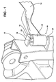
- a molded, integral joint connects first 12 and second 14 parts such that the second part 14 is rotatable relative to the first part 12.
- the integral joint 10 may be formed by injection molding or injection-compression molding.
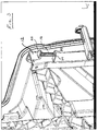
- the first part 12 is a semi-structural panel for a motor vehicle and the second part 14 is a vehicle door handle assembly. It is, however, appreciated that the first 12 and second 14 parts may be any of numerous structures for use in any of a variety of industries.
- the integral joint 10 includes a stationary member 16 extending between opposing ends 18, 20.
- a first tab 22 extends between one end 18 of the stationary member 16 and the first part 12.
- a second tab 24 is spaced apart from the first tab 22 and extends between the opposing end 20 of the stationary member 16 and the first part 12.
- the first 22 and second 24 tabs connect the stationary member 16 to the first part 12.
- the first 22 and second 24 tabs are offset from one another along the stationary member 16. It is appreciated that the shape of the first 22 and second 24 tabs may vary.
- a rotatable member or enclosure 28 extends out from one end of the second part 14.
- the rotatable member 28 surrounds the stationary member 16 and is free to rotate relative thereto. More specifically, the rotatable member 28 is not secured or attached to the stationary member 16 or to the first 22 and second 24 tabs. The rotatable member 28 is maintained along the stationary member 16 by the first 22 and second 24 tabs.
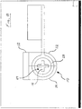
- the particular structure, configuration, and size of the stationary 16 and rotatable 28 members may vary. In accordance with these variations, one may vary a space 29 (shown in Figure 8 ) between the stationary 16 and rotatable 28 members to increase or decrease the ability of the rotatable member 28 to rotate about the stationary member 16.
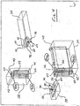
- a method of molding the integral joint 10 is now described with reference to Figures 4 through 8 .
- the method of molding the integral joint 10 utilizes a joint formation assembly, generally shown at 30, including a plurality of slides 32, 34, 36, 38.
- the plurality of slides includes first 32 and second 34 central slides and first 36 and second 38 end slides.
- moldable material is injected into the joint formation assembly 30 to form the integral joint 10.
- the first central slide 32 includes an inboard surface 40 defining an outer cavity half 42.
- the second central slide 34 includes an inboard surface 44 defining an outer cavity half 46.
- each of the outer cavity halves 42, 46 has a semi-circular shape.
- the second central slide 34 also includes a top surface 48 defining a passageway 50.
- the passageway 50 is fluidly connected to the outer cavity half 46.
- the joint formation assembly 30 When the joint formation assembly 30 is in the ready position, as shown in Figures 6 and 7 , the first 32 and second 34 central slides are moved against one another so that the inboard surfaces 40, 44 abut one another. At this time, the outer cavity halves 42, 46 are aligned with one another to form a continuous outer cavity 52, as shown in Figure 6 . Moldable material is introduced into the passageway 50 to fill the entire outer cavity 52 and eventually form the rotatable member or enclosure 28.
- each of the first 32 and second 34 central slides also includes an inner cavity portion 54, 56 that is divorced from the respective outer cavity half 42, 46 by a separating wall 59.
- Each inner cavity portion 54, 56 extends between opposing ends 60, 62.
- the first end slide 36 includes an inboard surface, generally indicated at 64, extending between an upper end 66 and a lower end 68.
- the inboard surface 64 defines an inner cavity portion 70 along the lower end 68.
- the inner cavity portion 70 is continuous with the inner cavity portion 56 of the second central slide 34.
- the inner cavity portion 70 closes around the inner cavity portion 54 at the end 60 thereof.
- the inboard surface 64 further defines an end cavity 72 that is shaped to form the tab 22.
- a passageway 74 is formed in the first end slide 36 for receiving moldable material that will eventually enter the inner cavity portions 54, 56 in order to form the stationary member 16.
- the inboard surface 64 of the first end slide 36 also includes end portions 76, 78 on either side of the inner cavity portion 70.
- the end portions 76, 78 abut the top surface 48 of the second central slide 34 to seal off the outer cavity half 46 and the passageway 50.
- moldable material entering the outer cavity half 46 from the passageway 50 is prevented from entering the inner cavity half 70 and the end cavity 72.
- the outer cavity half 46 is completely divorced from the inner cavity portions 56, 70.
- the second end slide 38 also includes an inboard surface 80 extending between an upper end 82 and a lower end 84.
- the inboard surface 80 defines an inner cavity portion 86 along the upper end 82.
- the inner cavity portion 86 is continuous with the inner cavity portion 54 of the first central slide 32. Together, the inner cavity portions 54, 56, 70, 86 form an inner cavity 87.
- the inner cavity portion 86 closes around the inner cavity portion 56 at the end 60 thereof.
- the inboard surface 80 further defines an end cavity 88 that is shaped to form the tab 24.
- the inboard surface 80 of the second end slide 38 also includes end portions 90, 92 on either side of the inner cavity portion 86.
- the end portions 90, 92 abut a bottom surface 94 of the first central slide 32 to seal off the outer cavity half 42.
- moldable material entering the outer cavity half 42 is prevented from entering the inner cavity portion 86 and the end cavity 88.
- the outer cavity half 42 is completely divorced from the inner cavity portions 54, 86.
- the molding of the integral joint 10 begins with the movement of the joint formation assembly 30 into the ready position, shown in Figures 6 and 7 .
- Moldable material is introduced into the first end slide 36 via the passageway 74.
- the moldable material fills the end cavities 72, 88 and the inner cavity portions 54, 56, 70, 86, which together form the inner cavity 87.
- the moldable material in the inner cavity 87 and the end cavities 72, 88 forms the stationary member 16 and the tabs 22, 24, respectively.
- Moldable material is also introduced into the second central slide 34 via the passageway 50.
- the moldable material fills the outer cavity 52 to form the rotatable member 28. It is appreciated that different moldable materials may be utilized to form the stationary member 16 and the rotatable member 28.
- the separating wall 59 and the end portions 76, 78, 90, 92 prevent the moldable material in the outer cavity 52 from entering the inner cavity 87.
- the rotatable member 28 independently and separately forms around the stationary member 16, which allows rotation of the rotatable member 28 about the stationary member 16. The end result is a permanent and flexible connection between the first part 12 and the second part 14.
- the particular order in which the rotatable member or enclosure 28 and the stationary structure 16 are molded may vary. More specifically, the molding of the rotatable member or enclosure 28 and the stationary member 16 can occur either simultaneously or sequentially.
Landscapes
- Engineering & Computer Science (AREA)
- Manufacturing & Machinery (AREA)
- Mechanical Engineering (AREA)
- Injection Moulding Of Plastics Or The Like (AREA)
- Moulds For Moulding Plastics Or The Like (AREA)
- Joints Allowing Movement (AREA)
Claims (5)
- Procédé pour mouler un joint intégré comprenant un élément fixe (16) raccordé à une première partie (12) par des languettes (22, 24) espacées et une enceinte (28) s'étendant à partir d'une seconde partie (14) et pouvant tourner autour de l'élément fixe (16) entre les languettes (22, 24) espacées, ledit procédé comprenant les étapes consistant à:prévoir un ensemble de formation de joint qui comprend des première (32) et seconde (34) coulisses centrales et des première (36) et seconde (38) coulisses d'extrémité, dans lequel la première coulisse centrale (32) définit une première moitié de cavité externe (42) et la seconde coulisse centrale (34) définit une seconde moitié de cavité externe (46), dans lequel chacune des première (32) et seconde (34) coulisses centrales définit en outre une partie de cavité interne (54, 56) qui est séparée de la moitié de cavité externe (42, 46) respective par une paroi de séparation (59), dans lequel la première coulisse d'extrémité (36) définit une partie de cavité interne qui est continue avec la première partie de cavité interne de la seconde coulisse centrale, et dans lequel la première coulisse d'extrémité définit en outre une première cavité d'extrémité (72) qui est formée afin de former une première languette (22), dans lequel la première coulisse d'extrémité (36) scelle la seconde moitié de cavité externe (46), dans lequel la seconde coulisse d'extrémité (38) définit une partie de cavité interne (86) qui est continue avec la partie de cavité interne (54) de la première coulisse centrale (32) de sorte que les parties de cavité internes (54, 56, 70, 86) forment ensemble une cavité interne (87), dans lequel la seconde coulisse d'extrémité (38) définit en outre une seconde cavité d'extrémité (88) qui est formée afin de former une seconde languette (24), dans lequel la seconde coulisse d'extrémité (38) scelle la première moitié de cavité externe (42) pour séparer la cavité interne (87) et les cavités d'extrémité (72, 88) de la cavité externe (52);introduire un matériau moulable dans la cavité interne (87) par une première voie de passage (74);remplir la cavité interne (87) avec le matériau moulable afin de former l'élément fixe (16);remplir les cavités d'extrémité (72, 88) avec le matériau moulable afin de former les languettes (22, 24) solidaires avec l'élément fixe (16);introduire le matériau moulable dans la cavité externe (52) par une seconde voie de passage (50);remplir la cavité externe (52) avec le matériau moulable afin de former l'enceinte (28); etformer l'élément fixe et les languettes séparément et indépendamment former l'enceinte (28) autour de l'élément fixe (16) et entre les languettes (22, 24) pour permettre le mouvement de rotation de l'enceinte (28) par rapport à l'élément fixe (16).
- Procédé de moulage selon la revendication 1, dans lequel l'étape consistant à introduire le matériau moulable dans la cavité interne (87) par la première voie de passage (74) afin de former l'élément fixe (16) comprend l'étape consistant à remplir la cavité interne (87) et les cavités d'extrémité (72, 88) avec un premier matériau moulable et l'étape consistant à introduire le matériau moulable dans la cavité externe (52) par la seconde voie de passage (50) afin de former l'enceinte (28) comprend l'étape consistant à remplir la cavité externe (52) avec un second matériau moulable différent du premier matériau moulable.
- Procédé de moulage selon la revendication 1, dans lequel les étapes consistant à former l'élément fixe (16) et former l'enceinte (28) se produisent simultanément.
- Procédé de moulage selon la revendication 1, dans lequel les étapes consistant à former l'élément fixe (16) et à former l'enceinte (28) se produisent de manière séquentielle.
- Procédé de moulage selon la revendication 1, comprenant l'étape consistant à modifier un espace (29) entre les cavités interne et externe (87, 52) pour augmenter ou diminuer la capacité de l'enceinte (28) à tourner autour de l'élément fixe (16).
Applications Claiming Priority (2)
| Application Number | Priority Date | Filing Date | Title |
|---|---|---|---|
| US81552406P | 2006-06-20 | 2006-06-20 | |
| PCT/CA2007/001113 WO2007147253A1 (fr) | 2006-06-20 | 2007-06-19 | Procédé et système de moulage de joint intégré |
Publications (3)
| Publication Number | Publication Date |
|---|---|
| EP2038111A1 EP2038111A1 (fr) | 2009-03-25 |
| EP2038111A4 EP2038111A4 (fr) | 2012-03-28 |
| EP2038111B1 true EP2038111B1 (fr) | 2016-07-20 |
Family
ID=38833032
Family Applications (1)
| Application Number | Title | Priority Date | Filing Date |
|---|---|---|---|
| EP07720028.5A Not-in-force EP2038111B1 (fr) | 2006-06-20 | 2007-06-19 | Procédé de moulage de joint intégré |
Country Status (5)
| Country | Link |
|---|---|
| US (2) | US8092738B2 (fr) |
| EP (1) | EP2038111B1 (fr) |
| CN (1) | CN101472736B (fr) |
| CA (1) | CA2654153C (fr) |
| WO (1) | WO2007147253A1 (fr) |
Families Citing this family (4)
| Publication number | Priority date | Publication date | Assignee | Title |
|---|---|---|---|---|
| EP2842713A1 (fr) * | 2013-09-03 | 2015-03-04 | Andreas Massold | Articulation |
| GB201712207D0 (en) * | 2017-07-29 | 2017-09-13 | Douglas Stephen | Armoured gate security & modular metal encased solar powered battery bank system for electrical supply to any gate without an electrical supply |
| CN111356566B (zh) * | 2017-10-10 | 2022-12-16 | 麦格纳外饰公司 | 主动式气动系统模内组装的铰链模块化框架 |
| DE102019131396A1 (de) * | 2019-11-21 | 2021-05-27 | Lisa Dräxlmaier GmbH | Einteiliges gussbauteil mit wenigstens einem integrierten anbauteil und verfahren zum herstellen eines gussbauteils |
Family Cites Families (33)
| Publication number | Priority date | Publication date | Assignee | Title |
|---|---|---|---|---|
| US2495539A (en) * | 1946-04-16 | 1950-01-24 | Conmar Prod Corp | Mold for slide fastener sliders |
| US3000049A (en) * | 1958-08-04 | 1961-09-19 | American Plastics Corp | Plastic hinge and method of making the same |
| US3456913A (en) * | 1967-02-21 | 1969-07-22 | Michael Lutz | Mold for making a container having an integrally molded two-piece hinge |
| US3737270A (en) * | 1971-09-27 | 1973-06-05 | T Fiddler | Clustered molds for injection molding two or more parts in pivotal assembled condition in a frame |
| US3785217A (en) * | 1972-07-17 | 1974-01-15 | Cons Foods Corp | Roller assembly and method of making the same |
| US4049231A (en) * | 1976-01-07 | 1977-09-20 | Michael Lutz | Mold for manufacturing an integrally molded ball and socket type hinge |
| AU5579380A (en) * | 1979-03-01 | 1980-09-04 | Itw Ltd. | Adjustable handle mounting |
| US4579709A (en) * | 1983-11-23 | 1986-04-01 | Nicholas Ferrari | Method for molding hinged article |
| US4573239A (en) * | 1984-08-17 | 1986-03-04 | The Stanley Works | Three knuckle hinge with bushing inserts in center knuckle and method of making same |
| US4751765A (en) * | 1986-12-05 | 1988-06-21 | Wu Chien C | Spring hinge |
| DE8700368U1 (de) * | 1987-01-09 | 1988-05-05 | Ramsauer, Dieter, 5620 Velbert | Aushängbares Verschwindscharnier für Schaltschränke |
| US4805947A (en) * | 1987-07-13 | 1989-02-21 | General Motors Corporation | Door handle assembly |
| DE3739122A1 (de) * | 1987-11-19 | 1989-06-01 | Braun Pebra Gmbh | Verfahren und vorrichtung zum herstellen von kunststoff-formteilen |
| US5895081A (en) * | 1995-04-24 | 1999-04-20 | Aisin Seiki Kabushiki Kaisha | Inside door handle assembly for vehicles |
| JP3228694B2 (ja) * | 1997-03-14 | 2001-11-12 | 株式会社東郷製作所 | ヒンジ構造 |
| US6053458A (en) * | 1998-01-08 | 2000-04-25 | Illinois Tool Works Inc. | Swivel hinge for a clip |
| US6036244A (en) * | 1999-04-08 | 2000-03-14 | General Motors Corporation | Vehicle door handle assembly |
| DE19958149A1 (de) | 1999-12-03 | 2001-06-07 | Volkswagen Ag | Kugelgelenk und Verfahren zu dessen Herstellung |
| US6468457B2 (en) * | 1999-12-15 | 2002-10-22 | Lear Corporation | Method of manufacturing a vehicle cup holder arm assembly |
| DE20006953U1 (de) * | 2000-04-15 | 2000-07-06 | Utescheny-Endos GmbH, 75059 Zaisenhausen | Puffereinrichtung für drehbare Bauteile, wie beispielsweise Dachhaltegriffe oder Sonnenblenden eines Fahrzeuges |
| IT1317948B1 (it) * | 2000-05-26 | 2003-07-21 | Sandro Galli | Struttura di cerniera perfezionata e stampo per il suo ottenimento. |
| WO2001098795A2 (fr) | 2000-06-19 | 2001-12-27 | Winko Satellite Limited | Systeme de surveillance par satellite |
| US6793869B2 (en) * | 2000-12-11 | 2004-09-21 | Lear Corporation | Method of manufacturing a vehicle pull handle assembly |
| US7229582B2 (en) * | 2003-04-04 | 2007-06-12 | Moriroku Kabushiki Kaisha | Method of two-stage injection molding of air conditioner outlet vent device |
| US20040244149A1 (en) * | 2003-06-04 | 2004-12-09 | Joseph Anscher | Hinge |
| US20040244145A1 (en) * | 2003-06-04 | 2004-12-09 | Joseph Anscher | Hinge |
| GB2404893A (en) * | 2003-08-15 | 2005-02-16 | Trw Systems Ltd | A hinge and method of moulding same |
| US7124471B2 (en) * | 2004-02-10 | 2006-10-24 | Primex Manufacturing Ltd. | Hidden hinge |
| US20060248682A1 (en) * | 2005-09-20 | 2006-11-09 | J&R Plastics | Stacker hinge |
| US20070234517A1 (en) * | 2006-04-05 | 2007-10-11 | Larson George D | Overmolded hinge with insert washer |
| US20080134466A1 (en) * | 2006-12-11 | 2008-06-12 | Trw Automotive U.S. Llc | Integrally molded hinge assembly and method of manufacturing the same |
| US7870646B2 (en) * | 2007-04-25 | 2011-01-18 | Illinois Tool Works Inc. | In-mold hinge assembly and method of fabricating the same |
| US7673892B2 (en) * | 2007-05-02 | 2010-03-09 | Magna International Inc. | Thixomold hinge assembly |
-
2007
- 2007-06-19 EP EP07720028.5A patent/EP2038111B1/fr not_active Not-in-force
- 2007-06-19 US US12/305,096 patent/US8092738B2/en not_active Expired - Fee Related
- 2007-06-19 CA CA2654153A patent/CA2654153C/fr not_active Expired - Fee Related
- 2007-06-19 CN CN200780022688.1A patent/CN101472736B/zh not_active Expired - Fee Related
- 2007-06-19 WO PCT/CA2007/001113 patent/WO2007147253A1/fr not_active Ceased
-
2011
- 2011-12-27 US US13/337,341 patent/US8756765B2/en not_active Expired - Fee Related
Also Published As
| Publication number | Publication date |
|---|---|
| WO2007147253A1 (fr) | 2007-12-27 |
| US8092738B2 (en) | 2012-01-10 |
| CN101472736A (zh) | 2009-07-01 |
| EP2038111A4 (fr) | 2012-03-28 |
| EP2038111A1 (fr) | 2009-03-25 |
| US8756765B2 (en) | 2014-06-24 |
| CN101472736B (zh) | 2013-09-25 |
| US20090174112A1 (en) | 2009-07-09 |
| CA2654153A1 (fr) | 2007-12-27 |
| US20120093576A1 (en) | 2012-04-19 |
| CA2654153C (fr) | 2015-05-19 |
Similar Documents
| Publication | Publication Date | Title |
|---|---|---|
| US7077742B2 (en) | Pressure relief valve and method of forming the same | |
| EP2038111B1 (fr) | Procédé de moulage de joint intégré | |
| US11318832B2 (en) | Stiffening assembly for a fuel tank | |
| US20060006202A1 (en) | Container closure and method of assembly | |
| US4546695A (en) | Louvered grille unit and method of its manufacture | |
| CN102056818A (zh) | 气溶胶致动系统及其制造方法 | |
| KR20060052813A (ko) | 자동차의 도어 또는 힌지 결합된 플랩을 위한 핸들 | |
| US20060033344A1 (en) | Vehicle latch and method of manufacturing the same | |
| US6712593B2 (en) | Combination of split bodies for use in assembling blower fan by hollow article molding process | |
| EP0915302A2 (fr) | Ensemble de pièces moulées ou extrudées | |
| US12017391B2 (en) | Active aero system in-mold assembly hinge modular frame | |
| US20010035222A1 (en) | Assembly of extruded or moulded parts | |
| US20060225361A1 (en) | Articulated window assembly with ball turret hinge | |
| EP2870014B1 (fr) | Procédé de moulage par injection d'un ensemble ayant un élément mobile | |
| KR100411916B1 (ko) | 프로펠러 팬의 사출 성형 방법 | |
| CA2510269A1 (fr) | Carenage et methode de fabrication | |
| JP5919684B2 (ja) | エアクリーナのケースの製造方法 | |
| US11852246B2 (en) | Valve assembly and method of producing the same | |
| US20220410449A1 (en) | One-piece cast component having at least one integrated attachment part, and method for producing a cast component | |
| JP3788288B2 (ja) | 風向調整装置の製造方法 | |
| CN113085141A (zh) | 一体成型定量杯及其壳体吹塑成型方法 | |
| JPH0592163U (ja) | 開閉カバーのヒンジ部構造 | |
| JP2000161292A (ja) | プロペラファンおよびプロペラファンの製造方法 |
Legal Events
| Date | Code | Title | Description |
|---|---|---|---|
| PUAI | Public reference made under article 153(3) epc to a published international application that has entered the european phase |
Free format text: ORIGINAL CODE: 0009012 |
|
| 17P | Request for examination filed |
Effective date: 20090119 |
|
| AK | Designated contracting states |
Kind code of ref document: A1 Designated state(s): AT BE BG CH CY CZ DE DK EE ES FI FR GB GR HU IE IS IT LI LT LU LV MC MT NL PL PT RO SE SI SK TR |
|
| AX | Request for extension of the european patent |
Extension state: AL BA HR MK RS |
|
| RBV | Designated contracting states (corrected) |
Designated state(s): DE FR GB |
|
| A4 | Supplementary search report drawn up and despatched |
Effective date: 20120224 |
|
| RIC1 | Information provided on ipc code assigned before grant |
Ipc: E05B 3/00 20060101ALI20120221BHEP Ipc: B29C 65/70 20060101ALI20120221BHEP Ipc: B29D 99/00 20100101AFI20120221BHEP |
|
| DAX | Request for extension of the european patent (deleted) | ||
| 17Q | First examination report despatched |
Effective date: 20121030 |
|
| REG | Reference to a national code |
Ref country code: DE Ref legal event code: R079 Ref document number: 602007047066 Country of ref document: DE Free format text: PREVIOUS MAIN CLASS: B29D0031000000 Ipc: B29C0065700000 |
|
| RIC1 | Information provided on ipc code assigned before grant |
Ipc: E05B 17/00 20060101ALI20151216BHEP Ipc: E05B 3/00 20060101ALI20151216BHEP Ipc: B29L 31/22 20060101ALI20151216BHEP Ipc: B29C 45/00 20060101ALI20151216BHEP Ipc: B29C 65/70 20060101AFI20151216BHEP |
|
| GRAP | Despatch of communication of intention to grant a patent |
Free format text: ORIGINAL CODE: EPIDOSNIGR1 |
|
| INTG | Intention to grant announced |
Effective date: 20160127 |
|
| GRAS | Grant fee paid |
Free format text: ORIGINAL CODE: EPIDOSNIGR3 |
|
| GRAA | (expected) grant |
Free format text: ORIGINAL CODE: 0009210 |
|
| AK | Designated contracting states |
Kind code of ref document: B1 Designated state(s): DE FR GB |
|
| REG | Reference to a national code |
Ref country code: GB Ref legal event code: FG4D |
|
| REG | Reference to a national code |
Ref country code: DE Ref legal event code: R096 Ref document number: 602007047066 Country of ref document: DE |
|
| REG | Reference to a national code |
Ref country code: DE Ref legal event code: R097 Ref document number: 602007047066 Country of ref document: DE |
|
| PLBE | No opposition filed within time limit |
Free format text: ORIGINAL CODE: 0009261 |
|
| STAA | Information on the status of an ep patent application or granted ep patent |
Free format text: STATUS: NO OPPOSITION FILED WITHIN TIME LIMIT |
|
| 26N | No opposition filed |
Effective date: 20170421 |
|
| REG | Reference to a national code |
Ref country code: DE Ref legal event code: R119 Ref document number: 602007047066 Country of ref document: DE |
|
| GBPC | Gb: european patent ceased through non-payment of renewal fee |
Effective date: 20170619 |
|
| REG | Reference to a national code |
Ref country code: FR Ref legal event code: ST Effective date: 20180228 |
|
| PG25 | Lapsed in a contracting state [announced via postgrant information from national office to epo] |
Ref country code: GB Free format text: LAPSE BECAUSE OF NON-PAYMENT OF DUE FEES Effective date: 20170619 Ref country code: DE Free format text: LAPSE BECAUSE OF NON-PAYMENT OF DUE FEES Effective date: 20180103 |
|
| PG25 | Lapsed in a contracting state [announced via postgrant information from national office to epo] |
Ref country code: FR Free format text: LAPSE BECAUSE OF NON-PAYMENT OF DUE FEES Effective date: 20170630 |