EP0915302A2 - Ensemble de pièces moulées ou extrudées - Google Patents
Ensemble de pièces moulées ou extrudées Download PDFInfo
- Publication number
- EP0915302A2 EP0915302A2 EP98308890A EP98308890A EP0915302A2 EP 0915302 A2 EP0915302 A2 EP 0915302A2 EP 98308890 A EP98308890 A EP 98308890A EP 98308890 A EP98308890 A EP 98308890A EP 0915302 A2 EP0915302 A2 EP 0915302A2
- Authority
- EP
- European Patent Office
- Prior art keywords
- frame
- flap valve
- aperture
- assembly according
- seat
- Prior art date
- Legal status (The legal status is an assumption and is not a legal conclusion. Google has not performed a legal analysis and makes no representation as to the accuracy of the status listed.)
- Withdrawn
Links
Images

Classifications
-
- B—PERFORMING OPERATIONS; TRANSPORTING
- B60—VEHICLES IN GENERAL
- B60H—ARRANGEMENTS OF HEATING, COOLING, VENTILATING OR OTHER AIR-TREATING DEVICES SPECIALLY ADAPTED FOR PASSENGER OR GOODS SPACES OF VEHICLES
- B60H1/00—Heating, cooling or ventilating devices
- B60H1/24—Ventilating devices where the heating or cooling is irrelevant
- B60H1/248—Air-extractors, air-evacuation from the vehicle interior
- B60H1/249—Air-extractors, air-evacuation from the vehicle interior using one-way valves
-
- B—PERFORMING OPERATIONS; TRANSPORTING
- B29—WORKING OF PLASTICS; WORKING OF SUBSTANCES IN A PLASTIC STATE IN GENERAL
- B29C—SHAPING OR JOINING OF PLASTICS; SHAPING OF MATERIAL IN A PLASTIC STATE, NOT OTHERWISE PROVIDED FOR; AFTER-TREATMENT OF THE SHAPED PRODUCTS, e.g. REPAIRING
- B29C37/00—Component parts, details, accessories or auxiliary operations, not covered by group B29C33/00 or B29C35/00
- B29C37/0078—Measures or configurations for obtaining anchoring effects in the contact areas between layers
- B29C37/0082—Mechanical anchoring
-
- B—PERFORMING OPERATIONS; TRANSPORTING
- B29—WORKING OF PLASTICS; WORKING OF SUBSTANCES IN A PLASTIC STATE IN GENERAL
- B29C—SHAPING OR JOINING OF PLASTICS; SHAPING OF MATERIAL IN A PLASTIC STATE, NOT OTHERWISE PROVIDED FOR; AFTER-TREATMENT OF THE SHAPED PRODUCTS, e.g. REPAIRING
- B29C37/00—Component parts, details, accessories or auxiliary operations, not covered by group B29C33/00 or B29C35/00
- B29C37/0078—Measures or configurations for obtaining anchoring effects in the contact areas between layers
- B29C37/0082—Mechanical anchoring
- B29C37/0085—Mechanical anchoring by means of openings in the layers
-
- B—PERFORMING OPERATIONS; TRANSPORTING
- B29—WORKING OF PLASTICS; WORKING OF SUBSTANCES IN A PLASTIC STATE IN GENERAL
- B29C—SHAPING OR JOINING OF PLASTICS; SHAPING OF MATERIAL IN A PLASTIC STATE, NOT OTHERWISE PROVIDED FOR; AFTER-TREATMENT OF THE SHAPED PRODUCTS, e.g. REPAIRING
- B29C45/00—Injection moulding, i.e. forcing the required volume of moulding material through a nozzle into a closed mould; Apparatus therefor
- B29C45/14—Injection moulding, i.e. forcing the required volume of moulding material through a nozzle into a closed mould; Apparatus therefor incorporating preformed parts or layers, e.g. injection moulding around inserts or for coating articles
- B29C45/14467—Joining articles or parts of a single article
-
- B—PERFORMING OPERATIONS; TRANSPORTING
- B29—WORKING OF PLASTICS; WORKING OF SUBSTANCES IN A PLASTIC STATE IN GENERAL
- B29C—SHAPING OR JOINING OF PLASTICS; SHAPING OF MATERIAL IN A PLASTIC STATE, NOT OTHERWISE PROVIDED FOR; AFTER-TREATMENT OF THE SHAPED PRODUCTS, e.g. REPAIRING
- B29C48/00—Extrusion moulding, i.e. expressing the moulding material through a die or nozzle which imparts the desired form; Apparatus therefor
- B29C48/03—Extrusion moulding, i.e. expressing the moulding material through a die or nozzle which imparts the desired form; Apparatus therefor characterised by the shape of the extruded material at extrusion
- B29C48/07—Flat, e.g. panels
-
- B—PERFORMING OPERATIONS; TRANSPORTING
- B29—WORKING OF PLASTICS; WORKING OF SUBSTANCES IN A PLASTIC STATE IN GENERAL
- B29C—SHAPING OR JOINING OF PLASTICS; SHAPING OF MATERIAL IN A PLASTIC STATE, NOT OTHERWISE PROVIDED FOR; AFTER-TREATMENT OF THE SHAPED PRODUCTS, e.g. REPAIRING
- B29C48/00—Extrusion moulding, i.e. expressing the moulding material through a die or nozzle which imparts the desired form; Apparatus therefor
- B29C48/03—Extrusion moulding, i.e. expressing the moulding material through a die or nozzle which imparts the desired form; Apparatus therefor characterised by the shape of the extruded material at extrusion
- B29C48/12—Articles with an irregular circumference when viewed in cross-section, e.g. window profiles
-
- B—PERFORMING OPERATIONS; TRANSPORTING
- B29—WORKING OF PLASTICS; WORKING OF SUBSTANCES IN A PLASTIC STATE IN GENERAL
- B29C—SHAPING OR JOINING OF PLASTICS; SHAPING OF MATERIAL IN A PLASTIC STATE, NOT OTHERWISE PROVIDED FOR; AFTER-TREATMENT OF THE SHAPED PRODUCTS, e.g. REPAIRING
- B29C48/00—Extrusion moulding, i.e. expressing the moulding material through a die or nozzle which imparts the desired form; Apparatus therefor
- B29C48/15—Extrusion moulding, i.e. expressing the moulding material through a die or nozzle which imparts the desired form; Apparatus therefor incorporating preformed parts or layers, e.g. extrusion moulding around inserts
-
- B—PERFORMING OPERATIONS; TRANSPORTING
- B29—WORKING OF PLASTICS; WORKING OF SUBSTANCES IN A PLASTIC STATE IN GENERAL
- B29C—SHAPING OR JOINING OF PLASTICS; SHAPING OF MATERIAL IN A PLASTIC STATE, NOT OTHERWISE PROVIDED FOR; AFTER-TREATMENT OF THE SHAPED PRODUCTS, e.g. REPAIRING
- B29C65/00—Joining or sealing of preformed parts, e.g. welding of plastics materials; Apparatus therefor
- B29C65/70—Joining or sealing of preformed parts, e.g. welding of plastics materials; Apparatus therefor by moulding
-
- B—PERFORMING OPERATIONS; TRANSPORTING
- B29—WORKING OF PLASTICS; WORKING OF SUBSTANCES IN A PLASTIC STATE IN GENERAL
- B29C—SHAPING OR JOINING OF PLASTICS; SHAPING OF MATERIAL IN A PLASTIC STATE, NOT OTHERWISE PROVIDED FOR; AFTER-TREATMENT OF THE SHAPED PRODUCTS, e.g. REPAIRING
- B29C70/00—Shaping composites, i.e. plastics material comprising reinforcements, fillers or preformed parts, e.g. inserts
- B29C70/68—Shaping composites, i.e. plastics material comprising reinforcements, fillers or preformed parts, e.g. inserts by incorporating or moulding on preformed parts, e.g. inserts or layers, e.g. foam blocks
- B29C70/84—Shaping composites, i.e. plastics material comprising reinforcements, fillers or preformed parts, e.g. inserts by incorporating or moulding on preformed parts, e.g. inserts or layers, e.g. foam blocks by moulding material on preformed parts to be joined
- B29C70/845—Shaping composites, i.e. plastics material comprising reinforcements, fillers or preformed parts, e.g. inserts by incorporating or moulding on preformed parts, e.g. inserts or layers, e.g. foam blocks by moulding material on preformed parts to be joined by moulding material on a relative small portion of the preformed parts
-
- B—PERFORMING OPERATIONS; TRANSPORTING
- B29—WORKING OF PLASTICS; WORKING OF SUBSTANCES IN A PLASTIC STATE IN GENERAL
- B29C—SHAPING OR JOINING OF PLASTICS; SHAPING OF MATERIAL IN A PLASTIC STATE, NOT OTHERWISE PROVIDED FOR; AFTER-TREATMENT OF THE SHAPED PRODUCTS, e.g. REPAIRING
- B29C66/00—General aspects of processes or apparatus for joining preformed parts
- B29C66/50—General aspects of joining tubular articles; General aspects of joining long products, i.e. bars or profiled elements; General aspects of joining single elements to tubular articles, hollow articles or bars; General aspects of joining several hollow-preforms to form hollow or tubular articles
- B29C66/51—Joining tubular articles, profiled elements or bars; Joining single elements to tubular articles, hollow articles or bars; Joining several hollow-preforms to form hollow or tubular articles
- B29C66/54—Joining several hollow-preforms, e.g. half-shells, to form hollow articles, e.g. for making balls, containers; Joining several hollow-preforms, e.g. half-cylinders, to form tubular articles
-
- B—PERFORMING OPERATIONS; TRANSPORTING
- B29—WORKING OF PLASTICS; WORKING OF SUBSTANCES IN A PLASTIC STATE IN GENERAL
- B29C—SHAPING OR JOINING OF PLASTICS; SHAPING OF MATERIAL IN A PLASTIC STATE, NOT OTHERWISE PROVIDED FOR; AFTER-TREATMENT OF THE SHAPED PRODUCTS, e.g. REPAIRING
- B29C66/00—General aspects of processes or apparatus for joining preformed parts
- B29C66/70—General aspects of processes or apparatus for joining preformed parts characterised by the composition, physical properties or the structure of the material of the parts to be joined; Joining with non-plastics material
- B29C66/71—General aspects of processes or apparatus for joining preformed parts characterised by the composition, physical properties or the structure of the material of the parts to be joined; Joining with non-plastics material characterised by the composition of the plastics material of the parts to be joined
Definitions
- the invention relates to a method of making a hingeable connection between two extruded or mouldable members, comprising the steps of extruding or moulding a first, relatively rigid, member, extruding or moulding a second member, and hingeably connecting respective regions of the two members together.
- the invention also relates to a flap valve assembly, comprising a frame defining an aperture, and a flap valve hingeably mounted on the frame and movable between a closed position in which it closes the aperture and an open position in which the aperture is open, the frame being made of relatively rigid material.
- the invention further relates to a method of making a hingeable connection between two extruded or moulded members, comprising the steps of extruding or moulding a first one of the members in relatively rigid material, and extruding or moulding a second one of the members in relatively rigid material.
- the invention yet further relates to a flap valve assembly, comprising a frame defining an aperture, and a flap valve hingeably mounted on the frame and movable between a closed position in which it closes the aperture and an open position in which the aperture is open, the frame and the flap valve being made of relatively rigid material.
- the invention still further relates to a flap valve assembly, comprising a frame defining an aperture, and a flap valve hingeably mounted on the frame and movable between a closed position in which it closes the aperture around an open position in which the aperture is open, the frame and the flap valve being made of relatively rigid material, the frame providing a seat extending at least partly around the periphery of the aperture for receiving a seal carried by the flap valve.
- the method as first set forth above is characterised in that the second member is relatively flexible whereby the remainder of the second member can hinge relative to the first member by virtue of its flexibility.
- the assembly as first set forth above is characterised in that the flap valve is made of relatively flexible material with a region thereof mechanically connected to a corresponding region of the frame whereby the flexibility of the material of the flap valve allows the remainder of it to hinge between the closed and opened positions.
- the method as secondly set forth above is characterised by the steps of including an interconnection formation in a region of the first member and including a complementary formation in a region of the second member, and bringing the two regions towards each other so that the formations hingeably interlock.
- the assembly as secondly set forth above is characterised in that a region of the frame incorporates an interconnection formation, and in that a region of the flap valve incorporates a complementary interconnection formation, the two formations hingeably interlocking.
- the assembly as thirdly set forth above is characterised in that the seat is mechanically joined to the frame.
- the parts 10,12 may be parts produced by moulding or extrusion, or by any other similar process, from thermoplastic or similar mouldable material. Instead, however, they could be metal parts or parts made from other materials.
- Each part 10,12 is formed with a respective through hole 14,16.
- the parts are joined together by placing them in an injection mould with their regions containing the holes 14,16 placed together.
- Suitable material such as thermoplastics material, is then injected into the mould, the geometry of the mould being such that the injected material 18 passes through both aligned holes 14,16 and forms enlarged heads 20,22. After solidifying, the moulded material 18 thus firmly holds the two parts 10,12 together.
- the two parts are held together mechanically by the enlarged heads 20,22 of the injected material.
- the material of the injected material 18 has no or very low physico-chemical compatability with the material of the parts 10,12.
- the injected material 18 may have such physico-chemical compatability with the material of the parts 10,12 that the interconnection of the two parts 10,12 by the injected material 18 is at least in part produced by physico-chemical bonding.
- Figure 2 shows a modification of the method and structure shown in Figure 1.
- the moulded material 18 embraces the distal edges of the parts 10,12 to hold them together.
- the gripping function carried out by the injected material 18 can be purely mechanical or can in least at part be due to physico-chemical bonding between the material 18 and the material of the parts 10,12 if suitable physico-chemical compatability exists.
- Figure 2 shows how the material 18 can be shaped so as not only to carry out the function of connecting the parts 10,12 together but also an additional function: in this case, the material 18 is extended to provide a sealing lip 24.
- Figures 3 and 4 show in cross-section a ventilation grill assembly 30 for use in a motor vehicle body.
- the assembly 30 could be a ventilation grill for controllably ventilating the passenger compartment of the vehicle.
- the assembly 30 comprises a rigid frame 32 moulded from suitable thermoplastics material such as polyamide or polypropylene.
- the frame 32 has side walls 32A and 32B and end walls 32C and 32D, and a dividing wall 32E.
- the walls define two generally rectangular apertures 34,36. Each of these apertures can be controllably opened and closed by means of a respective flap valve 38,40.
- the flap valves 38,40 are produced from flexible rubber by extrusion or moulding.
- Figure 3 shows the flap valves in the closed position.
- Each flap valve 38,40 is hingeably attached by a respective hinge 42,44 to the frame 32.
- hinge 42 hingeably connects the flap valve 38 to a shoulder 46 rigidly extending in a sideways-inclined direction from the dividing wall 32E.
- Hinge 44 hingeably connects the flap valve 40 to a rigid shoulder 48 extending in a sideways-inclined direction integrally from the end wall 32D.
- each aperture 34,36 may be bridged across by a rigid support 54,56 extending between the sidewalls 32A and 32B.
- the supports 54,56 help to support the mid-portions of the flap valves 38,40 in the closed position.
- the supports 54,56 may not be necessary, particularly where the cross-sectional areas of the apertures 34,36 are relatively small.
- Each hinge arrangement 42,44 comprises a respective series of studs 58,60 made of rigid thermoplastics material which are integrally moulded with the frame 32 and extend side by side in a row along the inclined shoulder 46,48, the studs extending through respective holes in the flap valve 38,40.
- the studs have enlarged heads to hold the flap valve in position.
- the process of producing the flap valves 38,40 ensures that they are provided with holes in the required positions for receiving the studs 58,60 for forming the hinges 42,44. Instead, the studs can become pierced through the material of the flap valve 38,40 during the injection moulding process. Hingeing takes place because of the flexibility of the material from which the flap valves 38,40 are made.
- the arrows A show the direction in which the flap valves 38,40 hinge to open the apertures 34,36. Opening and closing of the apertures may take place in response to creation of an appropriate pressure difference between one side of each flap valve and the other.
- the manufacturing process may comprise an initial stage for producing the flap valves 38,40 by extrusion or moulding in suitable flexible thermoplastics, rubber or silicone rubber material.
- the material may be textile-covered.
- the flap valves are then placed in or transferred automatically to another mould which is designed to produce the frame 30.
- the moulding process is then carried out to produce the frame 30.
- the material from which the flap valves 38,40 are produced must be such that it can withstand the conditions (temperature and pressure in particular) existing within the mould when the frame 30 is produced.
- the material of the flap valves 38,40 is selected so that it does not have physico-chemical compatability with the material from which the frame 30 is produced. In this way, adherence, or any substantial adherence, between the material of the flap valves 38,40 and the material of the frame 30 is prevented.
- the areas of the flap valves 38,40 which will come into contact with the material of the frame 30 during the moulding operation for the frame can be coated with suitable material to provide extra protection against adherence.
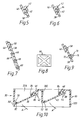
- Figure 5 shows a modified design for the hinge 42 (hinge 44 would be similar).
- the shoulder 46 ( Figure 3) on the dividing wall 32E of the frame 30 is moulded to produce a groove 62 which embracingly grips the corresponding edge of the flap valve 38 so as to secure the flap valve and provide the necessary hingeing effect.
- Figure 6 shows a modification of Figure 5 in which the flap valve 38 is provided with a series of extruded or moulded bosses 64 for increasing the gripping effect of the channel 62.
- Figure 7 shows how this can be achieved by attachment of an armature 66 such as made of metal or other rigid material (see Figure 8).
- the armature 66 can be moulded onto the flap valve 38,40 during its manufacturing process.
- Figure 7 shows how the armature 66 can be attached by means of integral studs passing through holes in the flap valve and having enlarged heads 68.
- FIG. 9 shows how a control tab 70 may be secured to the body of the flap valve 38,40, during its manufacture, by a further moulding operation, the tab 70 being attached by means of studs which pass through holes in the flap valve 38,40 and terminate in enlarged heads 72.
- the tab 30 has a hole 74 by means of which a control lever may be attached to control the position of the flap valve.
- the frame 30 is again moulded in rigid thermoplastics material such as polyamide or polypropylene.
- the flap valves 38,40 are also moulded or otherwise produced in rigid thermoplastics material, such as material similar to or the same as the material of the frame 30; the flap valves 38,40 in Figure 10 thus contrast with the flap valves in the assembly 30 of Figures 3 and 4 where they are made of flexible material.
- sealing of the closed flap valves 38,40 to the frame 30 is carried out by means of flexible seals 82,84 which are made of flexible material over-moulded onto the seats 50,52 and the shoulders 46,48.
- the flexible material of the sealing lips 82,84 must have suitable physico-chemical compatability with the material of the frame 30.
- the hinges 42,44 in the assembly 80 are formed by enlarged edges for the flap valves 38,40, whch are generally circular in cross-section and are fitted into complementary grooves 86,88 carried by the rigid shoulders 46,48, there being sufficient play within these grooves 86,88 to permit articulation of the flap valve.
- an initial stage can form the frame 30 by injection of the thermoplastics material. This can be followed by an over-moulding process to form the seals 82,84.
- flap valves 38,40 such as by injection moulding, can be carried out at the same time as the moulding of the frame 30 or completely separately.
- the flap valves are then assembled to, and secured to, the frame 30 by snapping the enlarged edges of the flap valves into the grooves 86,88.
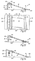
- the assembly 90 of Figures 11 and 12 provides only a single aperture 92 in this example.
- the frame 30 comprises the sidewalls 32A and 32B and end walls 32C and 32D (see Figure 12) but without the dividing wall 32E of Figures 3 and 10.
- the frame 30 is moulded in rigid thermoplastics material such as polypropylene.
- the aperture 92 is controlled by a single flap valve 38 which is also moulded in rigid thermoplastics material, preferably the same as that of the frame 30.
- the flap valve 38 is hingedly attached to the wall 32D by a hinge shown at 94 comprising flexible thermoplastics material which secures the flap valve 38 to the wall 32D because of the physico-chemical compatability of the two materials.
- the valve seat 96 is provided by rigid thermoplastics material (e.g. polyamide), again surrounding the three sides of the aperture 92 (that is, all sides except the hinge side), which is mechanically secured to the end wall 32C by means of a series of studs 98 integrally upstanding from a rigid integral lip 100 of the wall 32C and which pass through a series of complementary holes formed in the seat 96, the studs having enlarged heads 102.
- the seat 96 does not become secured to the lip 100 because of the lack of physico-chemical compatability between the two materials.
- Sealing between the flap valve 38 and the seat 96 is carried out by a seal 104 which extends around the four sides of the flap valve (that is, including the hinge side) and which is over-moulded onto the flap valve 38 and becomes secured thereto because of the physico-chemical compatability between the corresponding materials.
- the initial stage of the manufacturing process can comprise an injection moulding process to form the seat 96.
- injection of the material to form the remainder of the frame 30, and the flap valve 38 takes place.
- injection to produce the seal 104 and the hinge 94 takes place.
- steps can be carried out using a tri-injection press in which all three moulding stages could take place. Instead, a bi-injection press could take place for carrying out the two initial stages, with a mono-injection press to carry out the third stage. Suitable manipulators can be used to carry out transfers of the parts between the presses. Instead, three mono-injection presses could be used.
- Figure 13 also shows how the material of the hinge 94 and the material of the seal 104 can be moulded so as at least partly to be secured to the corresponding edges of the flap valve 38 by mechanical shaping. All parts can be made of polyamide except the hinge.
- an initial stage can inject the material to form the frame 30 including the seat 100A and also the body of the flap valve 38. Injection then takes place to form the hinge 94 and the seal 104.
- the construction is generally similar to that shown in Figure 13, except that the seat 96 is (like the arrangement of Figure 11) separate from the rigid shoulder 100 of the end wall 32C but attached to it through the intermediary of a mechanical fixture carried out during the moulding operation which attaches the flexible material to the flap valve 38 to form the hinge 94 and the seal 104.
- additional flexible thermoplastics material 106 attaches the seat 96 to the shoulder 100.
- An initial stage of the manufacturing process of the assembly 90 of Figure 14 comprises injection of the material to form the seat 96. This is followed by injection of similar rigid material to form the frame 30 and the flap valve 38. Thereafter, the flexible thermoplastics material is injected to form the hinge 94, the seal 104 and the fixture 106.
- the frame 30 can be modified by the addition of integrally moulded elements for carrying out supplementary functions (mounting attachments for fixtures, air deflectors and the like).
- the flap valves 38,40 can be provided with additional elements such as shown in Figures 7,8 and 9.
Landscapes
- Engineering & Computer Science (AREA)
- Mechanical Engineering (AREA)
- Physics & Mathematics (AREA)
- Thermal Sciences (AREA)
- Chemical & Material Sciences (AREA)
- Composite Materials (AREA)
- Manufacturing & Machinery (AREA)
- Injection Moulding Of Plastics Or The Like (AREA)
- Air-Flow Control Members (AREA)
- Moulds For Moulding Plastics Or The Like (AREA)
Applications Claiming Priority (2)
| Application Number | Priority Date | Filing Date | Title |
|---|---|---|---|
| GB9723304A GB2330793B (en) | 1997-11-04 | 1997-11-04 | Assembly of extruded or moulded parts |
| GB9723304 | 1997-11-04 |
Publications (2)
| Publication Number | Publication Date |
|---|---|
| EP0915302A2 true EP0915302A2 (fr) | 1999-05-12 |
| EP0915302A3 EP0915302A3 (fr) | 2000-05-31 |
Family
ID=10821576
Family Applications (1)
| Application Number | Title | Priority Date | Filing Date |
|---|---|---|---|
| EP98308890A Withdrawn EP0915302A3 (fr) | 1997-11-04 | 1998-10-30 | Ensemble de pièces moulées ou extrudées |
Country Status (2)
| Country | Link |
|---|---|
| EP (1) | EP0915302A3 (fr) |
| GB (1) | GB2330793B (fr) |
Cited By (15)
| Publication number | Priority date | Publication date | Assignee | Title |
|---|---|---|---|---|
| EP1491373A1 (fr) * | 2003-06-24 | 2004-12-29 | TRW Automotive U.S. LLC | Dispositif d' aération pour véhicule comprenant un soupape d'échappement |
| EP1527917A1 (fr) * | 2003-10-28 | 2005-05-04 | TRW Automotive Electronics & Components GmbH & Co. KG | Clapet anti-retour pour un système d'aération de véhicule |
| DE202006020365U1 (de) | 2006-12-01 | 2008-05-29 | Itw Automotive Products Gmbh & Co. Kg | Rückluftsperre zur Entlüftung des Innenraums eines Kraftfahrzeugs |
| WO2008068565A1 (fr) * | 2006-12-01 | 2008-06-12 | Itw Automotive Products Gmbh & Co. Kg | Ensemble de ventilation pour le limiteur de pression de l'intérieur d'une automobile |
| EP1972472A1 (fr) * | 2007-03-20 | 2008-09-24 | Behr GmbH & Co. KG | Dispositif de clapet pour la climatisation d'un véhicule automobile |
| WO2009070487A1 (fr) * | 2007-11-28 | 2009-06-04 | Illinois Tool Works Inc. | Ensemble de libération de pression |
| CN102770263A (zh) * | 2009-11-30 | 2012-11-07 | 空中客车运营简化股份公司 | 在航空器部件之间形成密封接合的方法 |
| CN103857512A (zh) * | 2011-10-14 | 2014-06-11 | 罗伯特·博世有限公司 | 用于制造机动车的发动机冷却风扇的框架的方法 |
| US20150165873A1 (en) * | 2012-02-21 | 2015-06-18 | Illinois Tool Works Inc. | Return air blocking device for ventilation of the interior of a motor vehicle |
| CN112212040A (zh) * | 2020-11-02 | 2021-01-12 | 黄妹 | 用于机动车内部的单向排气装置 |
| WO2022083454A1 (fr) | 2020-10-22 | 2022-04-28 | 嘉兴汉工汽车紧固件有限公司 | Dispositif de ventilation facilitant l'écoulement d'air à l'intérieur et à l'extérieur d'un véhicule |
| WO2022117132A1 (fr) * | 2020-12-01 | 2022-06-09 | Prihoda S.R.O. | Paroi de refroidisseur contenant une ouverture de sortie et un obturateur |
| WO2023050016A1 (fr) * | 2021-10-01 | 2023-04-06 | Markdom International Inc. | Soupape de décharge de pression de compartiment de véhicule moulée par injection |
| US12128740B2 (en) | 2021-12-10 | 2024-10-29 | Markdom International Inc. | Vehicle accessory apparatus with incomplete assembly indicator |
| WO2025108682A1 (fr) * | 2023-11-24 | 2025-05-30 | Siemens Mobility Austria Gmbh | Volet anti-retour |
Families Citing this family (3)
| Publication number | Priority date | Publication date | Assignee | Title |
|---|---|---|---|---|
| US6210266B1 (en) | 1999-03-15 | 2001-04-03 | Sarnamotive Blue Water, Inc. | Pressure relief valve and method of manufacturing the same |
| DE102011007904A1 (de) * | 2011-04-21 | 2012-10-25 | Behr Gmbh & Co. Kg | Dichtlippe für eine Lüftungsklappe einer Fahrzeugklimaanlage und Lüftungsklappe mit Dichtlippe |
| KR102162950B1 (ko) | 2016-03-11 | 2020-10-07 | 일리노이즈 툴 워크스 인코포레이티드 | 플랩-완충 압력 이완 조립체 |
Citations (1)
| Publication number | Priority date | Publication date | Assignee | Title |
|---|---|---|---|---|
| GB2298917A (en) | 1995-02-22 | 1996-09-18 | Draftex Ind Ltd | Pressure-responsive air extractor valve formed by moulding operation |
Family Cites Families (24)
| Publication number | Priority date | Publication date | Assignee | Title |
|---|---|---|---|---|
| GB524436A (en) * | 1938-09-06 | 1940-08-06 | Philips Nv | Improvements in or relating to electric apparatus comprising a system of conductors produced by a die-casting process |
| GB560251A (en) * | 1942-05-11 | 1944-03-27 | Distillers Co Yeast Ltd | Improvements in or relating to the jointing of plates, sheets and the like |
| GB560087A (en) * | 1942-07-01 | 1944-03-20 | William John Jarrard | Improvements in or relating to the formation of flexible joints in articles containing rigid parts made from plastics |
| US2849941A (en) * | 1953-11-13 | 1958-09-02 | Negoro Kaiji | Automobile ventilator |
| GB852413A (en) * | 1956-09-17 | 1960-10-26 | Curty & Cie | Improvements in or relating to gaskets and methods of producing the same |
| GB1192321A (en) * | 1968-01-10 | 1970-05-20 | Dover Eng Works Ltd | Improvements relating to Manhole and like Covers and Frames |
| FR1584599A (fr) * | 1968-07-23 | 1969-12-26 | ||
| AT332075B (de) * | 1972-12-22 | 1976-09-10 | Saint Gobain | Glasbaustein |
| GB1583862A (en) * | 1977-08-24 | 1981-02-04 | Drg Ltd | Lidded container |
| US4193174A (en) * | 1978-04-11 | 1980-03-18 | Portex, Inc. | Lever and fulcrum clamping assembly |
| US4343758A (en) * | 1979-07-02 | 1982-08-10 | Goralnik Charles D | Cut glass window pane |
| DE3731980C1 (de) * | 1987-09-23 | 1989-03-23 | Freudenberg Carl Fa | Jalousie zum bedarfsweisen Verschliessen einer durchstroembaren OEffnung |
| FR2624051B1 (fr) * | 1987-12-03 | 1990-04-06 | Michelin & Cie | Procede pour raccorder bout a bout les bords d'un tissu caoutchoute, destine a la fabrication d'une armature de carcasse, et pneumatique a armature de carcasse radiale obtenu |
| US4909245A (en) * | 1989-06-09 | 1990-03-20 | Wollenhaupt William H | Compact disposable mouth-to-mouth resuscitation device |
| US5197935A (en) * | 1989-11-13 | 1993-03-30 | Tetra Alpha Holdings S.A. | Package for flowable contents with an externally smoothly constructed sealing seam, a method of producing such a package and an apparatus for carrying out the method |
| JPH045031A (ja) * | 1990-04-24 | 1992-01-09 | Nec Home Electron Ltd | 樹脂成形品とその成形用金型並びにその成形用金型を用いた成形方法 |
| DE4023190C2 (de) * | 1990-07-20 | 1995-11-02 | United Carr Gmbh Trw | Rückluftsperre |
| US5194038A (en) * | 1992-06-29 | 1993-03-16 | Huron Plastics Group, Inc. | One-way air valve |
| FR2699870B1 (fr) * | 1992-12-31 | 1995-02-17 | Valeo Thermique Moteur Sa | Dispositif de régulation d'un flux d'air dans un passage de circulation, en particulier pour un radiateur de refroidissement de véhicule automobile. |
| ES2067342T3 (es) * | 1993-09-22 | 1995-03-16 | Siemens Ag | Procedimiento para la fabricacion de una instalacion de calefaccion y/o de aire acondicionado con una valvula de aire de chapaleta apoyada hermeticamente contra una pared de la caja, en especial para un automovil. |
| US5419739A (en) * | 1993-09-28 | 1995-05-30 | Trw Inc. | Flap-type pressure relief valve and method of forming the same |
| US5601117A (en) * | 1995-02-21 | 1997-02-11 | Trw Inc. | Flap-type pressure relief valve |
| DE19549124A1 (de) * | 1995-12-29 | 1997-07-03 | Reum Ag | Druckluftausgleichvorrichtung |
| US5727999A (en) * | 1997-02-28 | 1998-03-17 | Trw Inc. | Vehicle ventilation valve |
-
1997
- 1997-11-04 GB GB9723304A patent/GB2330793B/en not_active Expired - Fee Related
-
1998
- 1998-10-30 EP EP98308890A patent/EP0915302A3/fr not_active Withdrawn
Patent Citations (1)
| Publication number | Priority date | Publication date | Assignee | Title |
|---|---|---|---|---|
| GB2298917A (en) | 1995-02-22 | 1996-09-18 | Draftex Ind Ltd | Pressure-responsive air extractor valve formed by moulding operation |
Cited By (22)
| Publication number | Priority date | Publication date | Assignee | Title |
|---|---|---|---|---|
| US7044164B2 (en) | 2003-06-24 | 2006-05-16 | Trw Automotive U.S. Llc | Flap-type vehicle cabin exhauster |
| EP1491373A1 (fr) * | 2003-06-24 | 2004-12-29 | TRW Automotive U.S. LLC | Dispositif d' aération pour véhicule comprenant un soupape d'échappement |
| EP1527917A1 (fr) * | 2003-10-28 | 2005-05-04 | TRW Automotive Electronics & Components GmbH & Co. KG | Clapet anti-retour pour un système d'aération de véhicule |
| US8328609B2 (en) | 2006-12-01 | 2012-12-11 | Itw Automotive Products Gmbh & Co. Kg | Ventilation assembly for the pressure relief of the interior of an automobile |
| DE202006020365U1 (de) | 2006-12-01 | 2008-05-29 | Itw Automotive Products Gmbh & Co. Kg | Rückluftsperre zur Entlüftung des Innenraums eines Kraftfahrzeugs |
| WO2008068565A1 (fr) * | 2006-12-01 | 2008-06-12 | Itw Automotive Products Gmbh & Co. Kg | Ensemble de ventilation pour le limiteur de pression de l'intérieur d'une automobile |
| DE102006056868B4 (de) * | 2006-12-01 | 2011-06-01 | Itw Automotive Products Gmbh & Co. Kg | Rückluftsperre zur Entlüftung des Innenraums eines Kraftfahrzeugs |
| EP1972472A1 (fr) * | 2007-03-20 | 2008-09-24 | Behr GmbH & Co. KG | Dispositif de clapet pour la climatisation d'un véhicule automobile |
| US8360104B2 (en) | 2007-11-28 | 2013-01-29 | Illinois Tool Works Inc. | Pressure relief assembly |
| WO2009070487A1 (fr) * | 2007-11-28 | 2009-06-04 | Illinois Tool Works Inc. | Ensemble de libération de pression |
| CN102770263B (zh) * | 2009-11-30 | 2016-05-18 | 空中客车运营简化股份公司 | 在航空器部件之间形成密封接合的方法 |
| CN102770263A (zh) * | 2009-11-30 | 2012-11-07 | 空中客车运营简化股份公司 | 在航空器部件之间形成密封接合的方法 |
| CN103857512A (zh) * | 2011-10-14 | 2014-06-11 | 罗伯特·博世有限公司 | 用于制造机动车的发动机冷却风扇的框架的方法 |
| US20150165873A1 (en) * | 2012-02-21 | 2015-06-18 | Illinois Tool Works Inc. | Return air blocking device for ventilation of the interior of a motor vehicle |
| US10391838B2 (en) * | 2012-02-21 | 2019-08-27 | Illinois Tool Works Inc. | Return air blocking device for ventilation of the interior of a motor vehicle |
| WO2022083454A1 (fr) | 2020-10-22 | 2022-04-28 | 嘉兴汉工汽车紧固件有限公司 | Dispositif de ventilation facilitant l'écoulement d'air à l'intérieur et à l'extérieur d'un véhicule |
| CN112212040A (zh) * | 2020-11-02 | 2021-01-12 | 黄妹 | 用于机动车内部的单向排气装置 |
| WO2022117132A1 (fr) * | 2020-12-01 | 2022-06-09 | Prihoda S.R.O. | Paroi de refroidisseur contenant une ouverture de sortie et un obturateur |
| WO2023050016A1 (fr) * | 2021-10-01 | 2023-04-06 | Markdom International Inc. | Soupape de décharge de pression de compartiment de véhicule moulée par injection |
| US12427835B2 (en) | 2021-10-01 | 2025-09-30 | Markdom International Inc. | Injection molded vehicle compartment pressure relief valve |
| US12128740B2 (en) | 2021-12-10 | 2024-10-29 | Markdom International Inc. | Vehicle accessory apparatus with incomplete assembly indicator |
| WO2025108682A1 (fr) * | 2023-11-24 | 2025-05-30 | Siemens Mobility Austria Gmbh | Volet anti-retour |
Also Published As
| Publication number | Publication date |
|---|---|
| EP0915302A3 (fr) | 2000-05-31 |
| GB2330793B (en) | 2002-08-28 |
| GB9723304D0 (en) | 1998-01-07 |
| GB2330793A (en) | 1999-05-05 |
Similar Documents
| Publication | Publication Date | Title |
|---|---|---|
| GB2330793A (en) | Ventilation assembly and joining parts | |
| EP0861748B1 (fr) | Clapet de ventilation de véhicule unidirectionel | |
| EP1072380B1 (fr) | Joint d'étanchéité et son procédé de fabrication | |
| US5759097A (en) | Air extractor valve | |
| CA2274425C (fr) | Soupape de decharge et methode de fabrication | |
| EP1838545B1 (fr) | Module de fenetre fixe encapsule | |
| EP0628439B1 (fr) | Joint d'étanchéité pour fenêtre mobile de véhicule | |
| US7740307B2 (en) | Motor vehicle component and methods for its manufacture | |
| US8419108B2 (en) | Assembly of a tailgate shell and of a component intended to be attached to the shell | |
| US20010035222A1 (en) | Assembly of extruded or moulded parts | |
| GB2347890A (en) | A valve flap assembly formed by moulding | |
| US20020058124A1 (en) | Weather strip | |
| JPH08197947A (ja) | シール用又はガイド用構造体及びその製法 | |
| US5964496A (en) | Weather strip for motor vehicle and method for manufacturing the same | |
| US5972268A (en) | Method of forming a corner part of a weather strip | |
| US20150123310A1 (en) | Method for injection molding end muckets to a previously molded vehicle panel and prior to installation of a separately extruded and elongated compression seal | |
| US20240183372A1 (en) | Pin and Grommet Assembly | |
| US20060255306A1 (en) | Valve device | |
| US20140246803A1 (en) | Method for producing a frame for an engine cooling fan of a motor vehicle | |
| JPH11248044A (ja) | 中空グロメット | |
| US20050269741A1 (en) | Multi-cavity glass encapsulation method | |
| US6112468A (en) | Door weatherstripping for motor vehicle and method of manufacturing the same | |
| JPH07164978A (ja) | 自動車用ウエザーストリップ | |
| JP2000320695A (ja) | 成形品連結方法及びフラップ弁アセンブリ | |
| US20220341453A1 (en) | Fastener with Integral Seal |
Legal Events
| Date | Code | Title | Description |
|---|---|---|---|
| PUAI | Public reference made under article 153(3) epc to a published international application that has entered the european phase |
Free format text: ORIGINAL CODE: 0009012 |
|
| AK | Designated contracting states |
Kind code of ref document: A2 Designated state(s): DE ES FR IT |
|
| AX | Request for extension of the european patent |
Free format text: AL;LT;LV;MK;RO;SI |
|
| PUAL | Search report despatched |
Free format text: ORIGINAL CODE: 0009013 |
|
| AK | Designated contracting states |
Kind code of ref document: A3 Designated state(s): AT BE CH CY DE DK ES FI FR GB GR IE IT LI LU MC NL PT SE |
|
| AX | Request for extension of the european patent |
Free format text: AL;LT;LV;MK;RO;SI |
|
| AKX | Designation fees paid | ||
| 17P | Request for examination filed |
Effective date: 20001127 |
|
| RBV | Designated contracting states (corrected) |
Designated state(s): DE ES FR IT |
|
| RAP1 | Party data changed (applicant data changed or rights of an application transferred) |
Owner name: TRELLEBORG AB |
|
| STAA | Information on the status of an ep patent application or granted ep patent |
Free format text: STATUS: THE APPLICATION IS DEEMED TO BE WITHDRAWN |
|
| 18D | Application deemed to be withdrawn |
Effective date: 20020501 |