EP2039455A2 - Einstellbare und abnehmbare Kielbaugruppe und Blattführung für eine Stichsäge - Google Patents
Einstellbare und abnehmbare Kielbaugruppe und Blattführung für eine Stichsäge Download PDFInfo
- Publication number
- EP2039455A2 EP2039455A2 EP08164642A EP08164642A EP2039455A2 EP 2039455 A2 EP2039455 A2 EP 2039455A2 EP 08164642 A EP08164642 A EP 08164642A EP 08164642 A EP08164642 A EP 08164642A EP 2039455 A2 EP2039455 A2 EP 2039455A2
- Authority
- EP
- European Patent Office
- Prior art keywords
- housing
- assembly
- keel
- jigsaw
- keel assembly
- Prior art date
- Legal status (The legal status is an assumption and is not a legal conclusion. Google has not performed a legal analysis and makes no representation as to the accuracy of the status listed.)
- Granted
Links
Images


Classifications
-
- B—PERFORMING OPERATIONS; TRANSPORTING
- B23—MACHINE TOOLS; METAL-WORKING NOT OTHERWISE PROVIDED FOR
- B23D—PLANING; SLOTTING; SHEARING; BROACHING; SAWING; FILING; SCRAPING; LIKE OPERATIONS FOR WORKING METAL BY REMOVING MATERIAL, NOT OTHERWISE PROVIDED FOR
- B23D51/00—Sawing machines or sawing devices working with straight blades, characterised only by constructional features of particular parts; Carrying or attaching means for tools, covered by this subclass, which are connected to a carrier at both ends
- B23D51/02—Sawing machines or sawing devices working with straight blades, characterised only by constructional features of particular parts; Carrying or attaching means for tools, covered by this subclass, which are connected to a carrier at both ends of beds; of guiding arrangements for work-tables or saw carriers; of frames
- B23D51/025—Sawing machines or sawing devices working with straight blades, characterised only by constructional features of particular parts; Carrying or attaching means for tools, covered by this subclass, which are connected to a carrier at both ends of beds; of guiding arrangements for work-tables or saw carriers; of frames of arrangements for guiding the saw blade
- B23D51/026—Sawing machines or sawing devices working with straight blades, characterised only by constructional features of particular parts; Carrying or attaching means for tools, covered by this subclass, which are connected to a carrier at both ends of beds; of guiding arrangements for work-tables or saw carriers; of frames of arrangements for guiding the saw blade by plural opposed guide surfaces
- B23D51/028—Sawing machines or sawing devices working with straight blades, characterised only by constructional features of particular parts; Carrying or attaching means for tools, covered by this subclass, which are connected to a carrier at both ends of beds; of guiding arrangements for work-tables or saw carriers; of frames of arrangements for guiding the saw blade by plural opposed guide surfaces with adjustment of the guide surfaces by rotation about an axis parallel to the work support surface
-
- B—PERFORMING OPERATIONS; TRANSPORTING
- B27—WORKING OR PRESERVING WOOD OR SIMILAR MATERIAL; NAILING OR STAPLING MACHINES IN GENERAL
- B27G—ACCESSORY MACHINES OR APPARATUS FOR WORKING WOOD OR SIMILAR MATERIALS; TOOLS FOR WORKING WOOD OR SIMILAR MATERIALS; SAFETY DEVICES FOR WOOD WORKING MACHINES OR TOOLS
- B27G19/00—Safety guards or devices specially adapted for wood saws; Auxiliary devices facilitating proper operation of wood saws
- B27G19/08—Accessories for keeping open the saw kerf, e.g. riving knives or wedge plates
-
- Y—GENERAL TAGGING OF NEW TECHNOLOGICAL DEVELOPMENTS; GENERAL TAGGING OF CROSS-SECTIONAL TECHNOLOGIES SPANNING OVER SEVERAL SECTIONS OF THE IPC; TECHNICAL SUBJECTS COVERED BY FORMER USPC CROSS-REFERENCE ART COLLECTIONS [XRACs] AND DIGESTS
- Y10—TECHNICAL SUBJECTS COVERED BY FORMER USPC
- Y10T—TECHNICAL SUBJECTS COVERED BY FORMER US CLASSIFICATION
- Y10T29/00—Metal working
- Y10T29/49—Method of mechanical manufacture
- Y10T29/49815—Disassembling
-
- Y—GENERAL TAGGING OF NEW TECHNOLOGICAL DEVELOPMENTS; GENERAL TAGGING OF CROSS-SECTIONAL TECHNOLOGIES SPANNING OVER SEVERAL SECTIONS OF THE IPC; TECHNICAL SUBJECTS COVERED BY FORMER USPC CROSS-REFERENCE ART COLLECTIONS [XRACs] AND DIGESTS
- Y10—TECHNICAL SUBJECTS COVERED BY FORMER USPC
- Y10T—TECHNICAL SUBJECTS COVERED BY FORMER US CLASSIFICATION
- Y10T29/00—Metal working
- Y10T29/49—Method of mechanical manufacture
- Y10T29/49826—Assembling or joining
Definitions
- the present teachings relate to a jigsaw and more particularly relate to an adjustable and removable keel attachment that can remain in line with a housing of the jigsaw, while a shoe member is pivoted relative to the housing.
- a keel blade can be attached to a jigsaw to provide a relatively more accurate straight cut through a piece of sheet material than a jigsaw without the keel blade.
- the keel blade is traditionally attached to and removed from a housing of the jigsaw using tools and multiple fasteners, which can be a relatively complex process. In some instances, the keel blade needs to be uncoupled from the housing to perform a bevel cut.
- the present invention provides a jigsaw that includes a housing containing a motor activated by a trigger assembly.
- a shoe member preferably is pivotally connected to the housing and establishes an angle therebetween.
- the jigsaw preferably includes a keel assembly that includes a blade member that generally extends from the housing beyond the shoe member.
- the keel assembly preferably remains generally in line with the housing as the angle between the shoe member and the housing varies.
- the jigsaw preferably also includes a latch assembly capable of retaining and releasing the keel assembly from the housing.
- a first aspect of the invention provides a jigsaw comprising: a housing containing a motor activated by a trigger assembly; a shoe member pivotally connected to said housing and establishing an angle therebetween; a keel assembly having a blade member that generally extends from said housing beyond said shoe member, wherein said keel assembly remains generally in line with said housing as said angle between said shoe member and said housing varies; and a latch assembly capable of retaining and releasing said keel assembly from said housing.
- a second aspect of the invention provides a jigsaw comprising: a housing containing a motor activated by a trigger assembly; a shoe member pivotally connected to said housing and establishing an angle therebetween; a keel assembly having a blade member that generally extends from said housing beyond said shoe member, wherein said keel assembly remains generally in line with said housing as said angle between said shoe member and said housing varies; a lower carrier assembly that can be moved relative to said blade member so as to establish different positions relative to said housing, wherein said different positions are adapted to accommodate workpieces of differing sizes; and a latch assembly capable of retaining and releasing said keel assembly from said housing.
- a third aspect of the invention provides a method of positioning a shoe member and a keel assembly relative to a housing of a jigsaw, the method comprising: securing a keel assembly to the housing so that the keel assembly extends from the housing beyond the shoe member; pivoting the shoe member relative to the housing so that an angle formed between the housing and the shoe member is generally equal to an angle formed between the keel assembly and shoe member; and removing the keel assembly from the housing.
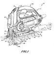
- a jigsaw 10 generally includes a housing 12 that can be formed of two half shells 14, 16.
- the housing 12 can contain a motor 18.
- the motor 18 can provide a reciprocating and/or pendulum motion to a cutting blade holder 22 on the end of a reciprocating shaft to drive a cutting blade 24 at one or more cutting angles 26 ( FIG. 7 ).
- a control member 28 on a side of the housing 12 can control a rate of the reciprocation and/or a magnitude of the pendulum motion of the cutting blade holder 22 on the reciprocating shaft and thus the cutting blade 24.
- a shoe member 30 can be coupled to a bottom 32 of the housing 12 in such a way as to permit the shoe member 30 to pivot relative to the housing 12.
- the cutting blade holder 22, the cutting blade 24, etc. can be orientated at various angles (i.e., one or more of the cutting angles 26 ( FIG. 7 )) relative to the shoe member 30.
- a bottom surface 34 of the shoe member 30 can abut a workpiece 36, which can be wood, plastic, metal, other suitable materials and one or more combinations thereof and can be in the form of pipe, sheet material, stock material, other suitable forms and/or materials and one or more combinations thereof.
- the shoe member 30 can be pivoted relative to the housing 12 to adjust the cutting angle 26 ( FIG. 7 ) of the jigsaw 10, e.g., at a forty-five degree cutting angle.
- an angle indicator wheel 38 can be rotatably coupled to the shoe member 30 and can indicate the cutting angle 26 of the jigsaw 10.
- a locking mechanism 40 can include a bevel lever 42 that can be adjusted between an unlocked condition and a locked condition, as shown in FIG. 1 . In the unlocked condition the locking mechanism 40 can permit the shoe member 30 to pivot relative to the housing 12. In the locked condition, as illustrated in FIG. 1 , the locking mechanism 40 can prevent the shoe member 30 from pivoting relative to the housing 12.
- the cutting angle 26 ( FIG. 7 ) to which the shoe member 30 can be pivoted relative to the housing 12, when the locking mechanism 40 is in the unlocked condition, can be indicated by the angle indicator wheel 38.
- a dust extraction port 44 can be formed on a rear portion 46 of the shoe member 30 such that a vacuum source 48 can be connected with various suitable connections to the dust extraction port 44.
- a dust extraction airflow 50 can be extracted from a cutting area 52. From the cutting area 52, the dust extraction airflow 50 can move through an airflow pathway formed in the shoe member 30 and directed out of the dust extraction port 44.
- the jigsaw 10 can include a laser module 80.
- the laser module 80 can project a laser light 82 and can produce a laser light pattern 84.
- the laser light pattern 84 can produce, for example, a sequence of dashes and/or dots beyond a front side 86 of the cutting blade 24 and can highlight a path of the cutting blade 24 through the workpiece 36.
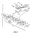
- the jigsaw 10 can also include a keel assembly 100 that can provide additional straight-line accuracy when cutting a straight line in the workpiece 36 (e.g., can help avoid wandering of the jigsaw cutting path).
- the keel assembly 100 can be pivoted with the housing 12 when the shoe member 30 is moved at an angle (i.e., the one or more cutting angles 26 ( FIG. 7 )) relative to the housing 12.
- the shoe member 30 can be pivoted relative to the housing 12 but the keel assembly 100 can remain generally in line with the housing 12 so as to provide, for example, a straight bevel cut through the workpiece 36, i.e., the cutting angle is not perpendicular to the workpiece 36 but the cutting path through the workpiece 36 is straight.
- the keel assembly 100 can be connected to the bottom 32 of the housing 12.
- the shoe member 30 can extend from the housing 12 beyond the shoe member 30 and distally outward (i.e., downward) from the bottom 32 of the jigsaw 10.
- the keel assembly 100 can include a keel blade member 102 to which a lower guide assembly 104 can be attached.
- the lower guide assembly 104 can be spaced at various predetermined distances from an upper guide assembly 106 that extends from the housing 12. By adjusting the lower guide assembly 104 relative to the upper guide assembly 106, the distance between the assemblies 104, 106 can be adjusted to accommodate workpieces having different thicknesses.
- the keel assembly 100 can also include a front connection portion 108 that can have a flange 110 in which an aperture 112 can be formed.
- the keel assembly 100 can further include a rear connection portion 114 that can define a lip 116.
- a rear connection portion 118 in the housing 12 can accept the lip 116 of the rear connection portion 114.
- the rear connection portion 114 of the keel assembly 100 can be received by the rear connection portion 118 of the housing 12 so that the lip 116 can pivot about the rear connection portion 118 of the housing 12.
- the keel assembly 100 can swing upwards so as to position the front connection portion 108 of the keel assembly 100 into engagement with a front connection portion 120 of the housing 12.
- the keel assembly 100 can also swing downwards when uncoupled from the housing 12 (illustrated in phantom line).
- the aperture 112 formed in the flange 110 can be accepted by a latch assembly 122 in the front connection portion 120 of the housing 12.
- the latch assembly 122 can include an actuator member 124 that can be pushed, retracted or the like.
- pushing the actuator member 124 into the latch assembly 122 can move a post 126 so as to move the post 126 out of the aperture 112 in the flange 110 of the front connection portion 108 of the keel assembly 100.
- the actuator member can be pushed by one or more fingers, thumbs, etc. of the user.
- the keel assembly 100 can swing downward about the lip 116 that can be held in the rear connection portion 118. As such, the keel assembly 100 can be uncoupled from the housing 12 via a hand operation and therefore no tools are required to do so.
- pressing the actuator member 124 can release a bias on the post 126 so that the post 126 can move (e.g., retract) when the keel assembly 100 is pulled away from the housing 12. Notwithstanding the specific mechanism that can move the post 126, when the actuator member 124 is in the extended position (e.g., not pressed by a user), the post 126 can be held by the aperture 112 formed in the front connection portion 108 of the keel assembly 100 to secure the keel assembly 100 to the housing 12.
- the keel assembly 100 can be secured to the housing 12 and the keel assembly 100 can remain in-line with the housing 12, while the jigsaw 10 is moved relative to the shoe member 30 to establish the various cutting angles 26.
- the one or more cutting angles 26 of the cutting blade 24 ( FIG. 1 ) of the jigsaw 10 are illustrated such that the cutting angle 26 (illustrated in solid line) is positioned at a zero degree cutting angle, i.e., a perpendicular cutting angle relative to the shoe member 30.
- a cutting angle 130 (shown in phantom line) can be positioned at about positive fifteen degrees, while a cutting angle 132 (shown in phantom line) can be positioned at about negative thirty degrees.
- a cutting angle 134 (shown in phantom line) can be positioned at about positive forty five degrees. It will be appreciated in light of the disclosure that various cutting angles can be implemented including, but not limited to, those cutting angles illustrated in FIG. 7 . In one aspect, the keel assembly 100 can be removed from the housing 12 regardless and at any of the cutting angles implemented.
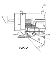
- the keel blade member 102 can define a channel 150 in which the lower carrier assembly 104 can move to adjust the distance between the lower carrier assembly 104 and the upper carrier assembly 106.
- the lower carrier assembly 104 can include an adjuster mechanism 152.
- the adjuster mechanism 152 can include an adjuster member 154 that can be retracted against the bias of a spring 156.
- a plug member 158 having a cam surface 160 can move out of alignment with an edge 162 of the channel 150 formed in the keel blade member 102.
- the cam surface 160 is moved out of alignment with the edge 162, the lower carrier assembly 104 can be moved between positions 164 relative to the keel blade member 102
- the positions 164 can include a top position 166, as shown in FIG. 5 and a lower position 168, as shown in FIG. 3 and again illustrated in phantom line in FIG. 5 .
- the different positions 164 of the lower carrier assembly 104 can be configured to accommodate varying lengths 170 of the cutting blade 24 for certain applications.
- the different positions 164 of the lower carrier assembly 104 can be implemented to accommodate differently sized workpieces.
- the plug member 158 can have a circular cam surface 172 that can be received by one of the pockets 174 formed from the edge 162 of the channel 150. While three pockets 174, i.e., a first pocket 176, a second pocket 178, a third pocket 180 are illustrated, it will be appreciated in light of the disclosure that varying amounts of the pockets 174 can be defined in the channel 150 in the keel blade member 102 and can be associated with the positions 164 of the lower carrier assembly 104.
- the lower carrier assembly 104 By moving the cam surface 160 out of contact with the edge 162 of the channel 150 formed in the keel blade member 102, the lower carrier assembly 104 can be moved relative to the keel blade member 102 to one of the selected positions 164. At one of the selected positions 164, the adjuster member 154 can be moved to an extended condition so that the cam surface 160 of the plug member 158 can again come into contact with the edge 162 of the channel 150 and thus hold the lower carrier assembly 104 in the selected position.
- the lower carrier assembly 104 can include a pair of arm members 182 that can be fastened together with the keel blade member 102 in between the arm members 182.
- Each of the arm members 182 can include one or more apertures.
- a rear aperture 184, a middle aperture 186 and a front aperture 188 can be formed on each of the arm members 182.
- the rear aperture 184 can accept a fastener 190 that can also be inserted into a groove 192 formed in the keel blade member 102. As the lower carrier assembly 104 is moved relative to the keel blade member 102, the fastener 190 can travel in the groove 192.
- One of the middle apertures 186 can be an oversized aperture (relative to other apertures) 194 on one of the arm members 182 so as to accept the plug member 158.
- the opposed middle aperture 186 on the opposite arm member 182 can accept a portion of the adjuster member 154.
- the adjuster member 154 can be inserted through the spring 156 that can be disposed between a surface 196 of one of the arm members 182 and a head 198 of the adjuster member 154.
- the adjuster member 154 can couple to the plug member 158 (e.g., with mechanical threads) to secure the spring 156 between the head 198 and the surface 196.
- the front aperture 188 can accept a fastener 200 that can rotatably hold a rolling member 202 between each of the arm members 182.
- the rolling member 202 can be configured with a groove 204 to accept a rear edge 206 ( FIG. 3 ) of the cutting blade 24.
- the keel assembly 100 can further include a keel block 230 that can attach to the keel blade member 102.
- the keel blade member 102 can define a first protrusion 232 and a second protrusion 234.
- the first protrusion 232 can include an aperture 236 while the second protrusion 234 can include a second aperture 238.
- a portion of the keel blade member 102, including the protrusions 232, 234 can be accepted within a groove 240 (shown in broken line) formed within the keel block 230.
- Fasteners 242 can be passed through apertures 244 formed in the keel block 230 and the apertures 236, 238 formed in the keel blade member 102 near the keel blade member 102 to the keel block 230.
- the keel block 230 can connect to the housing 12, as partially shown in FIG. 3 .
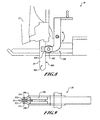
- an upper carrier assembly 300 can include a rolling member 302 or other suitable member that can abut a rear (i.e., non-cutting) edge 206 of the cutting blade 24 of the jigsaw 10 in accordance with further aspects of the present teachings.
- two guide members 306 can extend and can terminate at a position that almost touches a side 308 of the cutting blade 24.
- a hardened portion 312 can be positioned so that when the cutting blade 24 contacts the guide members 306, the cutting blade 24 can contact the hardened portions 312.
- Each of the hardened portions 312 can be harder than the material of which the guide members 306 are comprised.
- twisting of the cutting blade 24 can be due to the cutting blade 24 following a grain of wood especially in wet (green) wood.
- the guide members 306 and especially the hardened portions 312 in close proximity to the sides 308 of the cutting blade 24 can reduce the twisting of the cutting blade 24 and reduce deviations from a straight cutting line.
- the ends 310 of the guide members 306 can be kept close enough to the cutting blade 24 to reduce the twist of the cutting blade 24 because the cutting blade 24 can be prevented from twisting (or twisting to such a degree) due to the hardened portions 312 that can at least partially obstruct the sides 308 of the twisting cutting blade 24.
- twisting can be due to forces between the cutting blade 24 and the workpiece 36 and not otherwise due to an optionally implemented scrolling functionality that can impart a twist on the cutting blade 24 to, among other things, make it relatively easier to turn the cutting blade in decorative cutting with the jigsaw.
Landscapes
- Life Sciences & Earth Sciences (AREA)
- Engineering & Computer Science (AREA)
- Mechanical Engineering (AREA)
- Wood Science & Technology (AREA)
- Forests & Forestry (AREA)
- Sawing (AREA)
Applications Claiming Priority (1)
| Application Number | Priority Date | Filing Date | Title |
|---|---|---|---|
| US11/859,172 US8033026B2 (en) | 2007-09-21 | 2007-09-21 | Adjustable and removable keel assembly and blade guide for a jigsaw |
Publications (3)
| Publication Number | Publication Date |
|---|---|
| EP2039455A2 true EP2039455A2 (de) | 2009-03-25 |
| EP2039455A3 EP2039455A3 (de) | 2011-08-10 |
| EP2039455B1 EP2039455B1 (de) | 2015-07-08 |
Family
ID=40120429
Family Applications (1)
| Application Number | Title | Priority Date | Filing Date |
|---|---|---|---|
| EP08164642.4A Not-in-force EP2039455B1 (de) | 2007-09-21 | 2008-09-18 | Einstellbare und abnehmbare Kielbaugruppe und Blattführung für eine Stichsäge |
Country Status (4)
| Country | Link |
|---|---|
| US (2) | US8033026B2 (de) |
| EP (1) | EP2039455B1 (de) |
| CN (1) | CN201329450Y (de) |
| AU (1) | AU2008221557A1 (de) |
Cited By (2)
| Publication number | Priority date | Publication date | Assignee | Title |
|---|---|---|---|---|
| EP2567769A1 (de) * | 2011-09-12 | 2013-03-13 | Black & Decker Inc. | Stichsäge |
| US9899899B2 (en) | 2013-10-25 | 2018-02-20 | Black & Decker Inc. | Handheld power tool with compact AC switch |
Families Citing this family (19)
| Publication number | Priority date | Publication date | Assignee | Title |
|---|---|---|---|---|
| US9364907B2 (en) | 2007-12-11 | 2016-06-14 | Black & Decker Inc. | Jigsaw blade |
| DE102008001479A1 (de) * | 2008-04-30 | 2009-11-05 | Robert Bosch Gmbh | Elektrowerkzeugmaschine |
| DE102008055061A1 (de) * | 2008-12-22 | 2010-06-24 | Robert Bosch Gmbh | Führungssystem für Werkzeugmaschinen |
| US8328381B2 (en) | 2009-02-25 | 2012-12-11 | Black & Decker Inc. | Light for a power tool and method of illuminating a workpiece |
| US20110058356A1 (en) | 2009-02-25 | 2011-03-10 | Black & Decker Inc. | Power tool with light emitting assembly |
| US8317350B2 (en) | 2009-02-25 | 2012-11-27 | Black & Decker Inc. | Power tool with a light for illuminating a workpiece |
| US12059780B2 (en) | 2010-09-30 | 2024-08-13 | Black & Decker Inc. | Lighted power tool |
| US9028088B2 (en) | 2010-09-30 | 2015-05-12 | Black & Decker Inc. | Lighted power tool |
| US9328915B2 (en) | 2010-09-30 | 2016-05-03 | Black & Decker Inc. | Lighted power tool |
| US8857066B2 (en) * | 2011-08-22 | 2014-10-14 | Robert Bosch Gmbh | Power saw including an impact mechanism |
| USD675077S1 (en) * | 2011-09-23 | 2013-01-29 | Black & Decker Inc. | Jigsaw |
| US9242355B2 (en) | 2012-04-17 | 2016-01-26 | Black & Decker Inc. | Illuminated power tool |
| JP5995785B2 (ja) * | 2013-05-31 | 2016-09-21 | 株式会社マキタ | 刈払機 |
| WO2015050055A1 (ja) * | 2013-10-01 | 2015-04-09 | 日立工機株式会社 | 切断工具 |
| CN103722591A (zh) * | 2014-01-03 | 2014-04-16 | 华国洋 | 一种曲线锯的直线引导器 |
| DE102014226025A1 (de) * | 2014-12-16 | 2016-06-16 | Robert Bosch Gmbh | Optische Anzeigevorrichtungseinheit zur Verwendung in einer externen Anwendungseinheit |
| US10207348B2 (en) * | 2016-06-08 | 2019-02-19 | Jpw Industries Inc. | Dual position blade guide for vertical or horizontal position of band saw |
| US10136655B2 (en) * | 2016-10-19 | 2018-11-27 | William M Haack | Saw blade illuminating safety device |
| US10544597B2 (en) * | 2017-12-04 | 2020-01-28 | Rhino Tools and Equipment Inc. | Tool attachment for raking mortar joints |
Family Cites Families (218)
| Publication number | Priority date | Publication date | Assignee | Title |
|---|---|---|---|---|
| US1102018A (en) * | 1912-06-06 | 1914-06-30 | Kerner Mfg Company | Power-driven handsaw. |
| GB221671A (en) | 1923-10-22 | 1924-09-18 | George Scattergood | Improvements in or relating to guards for circular saws |
| DE716266C (de) | 1937-06-01 | 1942-01-15 | Hans Ehlermann Dipl Ing | Einrichtung zum Abfuehren der Waerme aus dem Rotorkern von Elektrohandwerkzeugen |
| US2377673A (en) * | 1944-08-21 | 1945-06-05 | Clarence F Chaddock | Blade guide for motor-driven circular handsaws |
| US2623557A (en) | 1951-06-05 | 1952-12-30 | John T Kendall | Portable power-driven recessing apparatus |
| DE1628899U (de) | 1951-07-17 | 1951-10-04 | Richard Muetschele | Abfuell-vorrichtung fuer fluessiggase. |
| US2749951A (en) * | 1952-04-17 | 1956-06-12 | Tetzner Gustav | Band saw blade guide |
| US2775272A (en) | 1953-11-27 | 1956-12-25 | Walter A Papworth | Portable power driven reciprocable cutting tool |
| US2819742A (en) * | 1955-07-05 | 1958-01-14 | Oster John Mfg Co | Kerf guide and splitter |
| DE1760076U (de) | 1957-11-26 | 1958-01-16 | Metabowerk Closs Rauch & Schni | Schutzisoliertes elektrowerkzeug, insbesondere stichsaege. |
| US2934106A (en) * | 1958-01-09 | 1960-04-26 | Continental Machines | Saw band guide |
| DE1795934U (de) | 1958-02-11 | 1959-09-17 | Scintilla Ag | Zusaetzliche vorrichtung fuer eine motorisch angetriebene handsaege. |
| US2916062A (en) * | 1958-09-18 | 1959-12-08 | Dormeyer Corp | Splitter for portable electric saw |
| US3093773A (en) * | 1959-03-23 | 1963-06-11 | Fed Pacific Electric Co | Panelboard with circuit protective devices |
| US3087519A (en) * | 1960-11-25 | 1963-04-30 | Black & Decker Mfg Co | Pivoting shoe for portable electric jig saw |
| US3146809A (en) | 1961-04-06 | 1964-09-01 | Skil Corp | Adjustable guide plate for jig saws |
| US3131736A (en) * | 1961-04-10 | 1964-05-05 | Milwaukee Electric Tool Corp | Portable motor driven jig saw |
| US3109465A (en) | 1961-05-19 | 1963-11-05 | Sure Hit Products Inc | Saw guide assemblies |
| US3116768A (en) * | 1962-05-07 | 1964-01-07 | Lasar William | Band saw guide |
| DE1279923B (de) * | 1965-01-21 | 1968-10-10 | Scintilla Ag | Einrichtung zur Erzeugung einer zusaetzlichen Vorschubbewegung fuer das Saegeblatt einer Stichsaegemaschine |
| US3353573A (en) | 1965-05-19 | 1967-11-21 | Mc Graw Edison Co | Portable power tool |
| DE1278728B (de) * | 1966-03-25 | 1968-09-26 | Ackermann U Schmitt K G | Fuehrungseinrichtung an einer motorisch angetriebenen Handstichsaege |
| US3388728A (en) * | 1966-04-15 | 1968-06-18 | Martin Marietta Corp | Portable power tools |
| US3457796A (en) * | 1966-06-23 | 1969-07-29 | Rockwell Mfg Co | Tool |
| US3461732A (en) | 1966-12-19 | 1969-08-19 | Rockwell Mfg Co | Portable power driven reciprocating saw |
| US3478786A (en) | 1967-02-03 | 1969-11-18 | Otto Hendrickson | Adjustably controlled saber saw |
| US3542097A (en) | 1968-05-02 | 1970-11-24 | Singer Co | Chuck assembly for sabre saws |
| US3834019A (en) | 1972-11-22 | 1974-09-10 | Maremont Corp | Apparatus for cutting exhaust system tubes |
| US3805383A (en) * | 1972-11-22 | 1974-04-23 | Maremont Corp | Exhaust system tube cutting apparatus with improved cutting efficiency |
| SE395606B (sv) | 1973-12-04 | 1977-08-22 | Persson Curt | Saganordning for uppskerning av ett gipsforband eller annan pa likartat sett utformad kropp |
| DE2435845C2 (de) | 1974-07-25 | 1984-09-20 | Metabowerke KG Closs, Rauch & Schnizler, 7440 Nürtingen | Motorisch angetriebene Stichsäge mit schrägstellbarem Tisch |
| US3938251A (en) * | 1975-03-10 | 1976-02-17 | The Raymond Lee Organization, Inc. | Saber or jig saw with demountable foot plate and shield |
| US3969796A (en) * | 1975-09-17 | 1976-07-20 | General Electric Company | Releasable fastening arrangement for a radio housing and a battery housing |
| DE2546527C2 (de) * | 1975-10-17 | 1993-05-27 | Robert Bosch Gmbh, 7000 Stuttgart | Stichsäge |
| DE2650470C2 (de) | 1976-11-04 | 1984-03-22 | Eugen Lutz GmbH u. Co Maschinenfabrik, 7130 Mühlacker | Stichsäge |
| DE2655583C2 (de) * | 1976-12-08 | 1982-07-01 | Black & Decker, Inc., 19711 Newark, Del. | Stichsäge |
| US4191917A (en) * | 1977-08-25 | 1980-03-04 | Disston, Inc. | Battery pack rechargeable in recessed or flush-type receptacles |
| US4262421A (en) * | 1978-08-11 | 1981-04-21 | Eugen Lutz Gmbh & Co. Maschinenfabrik | Keyhole saw |
| US4213242A (en) * | 1979-01-22 | 1980-07-22 | Partington Everett J | Attachment for saber saw |
| US4250624A (en) * | 1979-01-22 | 1981-02-17 | Partington Everett J | Miter table for use with a saber saw |
| US4257297A (en) * | 1979-01-31 | 1981-03-24 | Peter Nidbella | Circular saw with visual cut line indicator |
| US4272889A (en) * | 1979-02-26 | 1981-06-16 | Omark Industries, Inc. | Portable saw |
| US4255006A (en) * | 1979-06-11 | 1981-03-10 | Conair Corporation | Strain-relief member for reducing torsional strains in line cord |
| US4255858A (en) * | 1979-06-18 | 1981-03-17 | Getts Sidney Arthur | Jig saw with orbitally movable blade |
| US4238884A (en) | 1979-06-19 | 1980-12-16 | Black & Decker Inc. | Orbital jig saw |
| US4240204A (en) | 1979-06-19 | 1980-12-23 | Black & Decker Inc. | Jig saw |
| JPS6119487Y2 (de) * | 1979-06-19 | 1986-06-12 | ||
| US4283855A (en) | 1980-04-07 | 1981-08-18 | The Singer Company | Sabre saw with rotatable saw bar |
| DE8012652U1 (de) | 1980-05-09 | 1982-01-28 | Scintilla Ag, Solothurn | Handwerkzeugmaschine, insbesondere Stichsäge |
| DE3021801C2 (de) | 1980-06-11 | 1985-03-21 | Licentia Patent-Verwaltungs-Gmbh, 6000 Frankfurt | Stichsäge mit am Sägengehäuse befestigbarem Auflagetisch |
| DE8033115U1 (de) | 1980-12-12 | 1981-05-21 | Zimlich, Ernst, 8000 München | Saege |
| US4351112A (en) | 1981-02-20 | 1982-09-28 | The Singer Company | Sabre saw bar and blade holder |
| DE3118758C2 (de) | 1981-05-12 | 1986-04-30 | Licentia Patent-Verwaltungs-Gmbh, 6000 Frankfurt | Vorrichtung zur Erzeugung und Verstellung einer zusätzlichen Vorschubbewegung quer zur Längsrichtung des Sägeblatts einer Stichsägemaschine |
| DE3222426C1 (de) | 1982-06-15 | 1983-12-22 | Metabowerke GmbH & Co, 7440 Nürtingen | Elektrohandwerkzeug, insbesondere Stichsäge für Heimwerker |
| JPS59163608A (ja) | 1983-03-08 | 1984-09-14 | Hitachi Koki Co Ltd | ジグソ− |
| DE3329971A1 (de) * | 1983-08-19 | 1985-03-07 | Robert Bosch Gmbh, 7000 Stuttgart | Steuer- und bedienvorrichtung fuer ein elektrisches handwerkzeug |
| DE3403762A1 (de) | 1984-02-03 | 1985-08-14 | Festo KG, 7300 Esslingen | Einrichtung zur loesbaren befestigung eines spaltkeils an einer saege |
| DE3408847A1 (de) | 1984-03-10 | 1985-11-14 | Black & Decker Inc., Newark, Del. | Stichsaege |
| US4545123A (en) | 1984-04-09 | 1985-10-08 | Skil Corporation | Combination jig saw adjusting mechanism |
| GB2158393B (en) | 1984-05-11 | 1987-05-20 | Black & Decker Inc | Scroller jig saw |
| DE3420442A1 (de) * | 1984-06-01 | 1985-12-05 | Festo KG, 7300 Esslingen | Stichsaege |
| US4614037A (en) | 1984-08-10 | 1986-09-30 | Black & Decker, Inc. | Accessory storage device for electric jigsaw |
| US4675999A (en) * | 1984-11-16 | 1987-06-30 | Hitachi Koki Company, Ltd. | Portable power tool equipped with dust collector |
| DE3543764A1 (de) | 1984-12-13 | 1986-06-19 | Vsesojuznyj naučno-issledovatel'skij i proektno-konstruktorskij institut mechanizirovannogo i ručnogo stroitel'no-montažnogo instrumenta, vibratorov i stroitel'no-otdeločnych mašin VNNISMI, Chimki, Moskovskaja oblast' | Mechanische laubsaege |
| DE3446278A1 (de) | 1984-12-19 | 1986-06-26 | Metabowerke GmbH & Co, 7440 Nürtingen | Stichsaege |
| DE3546547C2 (en) | 1985-03-16 | 1989-05-24 | Festo Kg, 7300 Esslingen, De | Jig saw |
| DE3546700C2 (en) | 1985-03-16 | 1990-10-25 | Festo Kg, 7300 Esslingen, De | Portable power fret saw |
| DE8507818U1 (de) | 1985-03-16 | 1987-02-19 | Festo KG, 7300 Esslingen | Stichsäge |
| US4628605A (en) | 1985-06-10 | 1986-12-16 | Porter-Cable Corporation | Orbital bayonet saw |
| US4730397A (en) * | 1985-08-09 | 1988-03-15 | Black & Decker, Inc. | Jig saw with two-piece shoe |
| DE3608301A1 (de) | 1986-03-13 | 1987-09-17 | Metabowerke Kg | Stichsaege mit einem von hand fuehrbaren maschinengehaeuse |
| DE3613279A1 (de) * | 1986-04-19 | 1987-10-22 | Festo Kg | Stichsaege |
| DE3712236A1 (de) * | 1987-04-10 | 1988-10-27 | Bosch Gmbh Robert | Stichsaege |
| US4833782A (en) * | 1987-06-01 | 1989-05-30 | Robert E. Strauss | Saber saw tracing light |
| SU1558674A1 (ru) | 1987-06-23 | 1990-04-23 | Московское Научно-Производственное Объединение По Механизированному Строительному Инструменту И Отделочным Машинам | Механический лобзик |
| DE3820752A1 (de) | 1988-06-18 | 1989-12-21 | Reich Maschf Gmbh Karl | Stichsaege mit absaugung |
| US4962681A (en) | 1988-11-09 | 1990-10-16 | Yang Tai Her | Modular manual electric appliance |
| US5208525A (en) * | 1988-12-10 | 1993-05-04 | Gardena Kress + Kastner Gmbh | Electric power supply assembly for a cordless electric appliance |
| US4969830A (en) | 1989-06-12 | 1990-11-13 | Grid Systems Corporation | Connection between portable computer components |
| DE3921891A1 (de) | 1989-07-04 | 1991-01-17 | Black & Decker Inc | Stichsaege |
| US4932294A (en) * | 1989-07-18 | 1990-06-12 | Chang Jung C | DIY electric hand tool having a chamber for accommodating tool heads not in use |
| US4973205A (en) | 1989-12-18 | 1990-11-27 | Silas Spaulding | Hand drill apparatus |
| GB8928879D0 (en) | 1989-12-21 | 1990-02-28 | Amp Gmbh | Connector keying system |
| US5010652A (en) * | 1990-03-19 | 1991-04-30 | Miletich David J | Optically guided power sabre saw |
| DE4009405A1 (de) * | 1990-03-23 | 1991-09-26 | Nienstedt Heinz Maschf | Saegebandfuehrung |
| US5038481A (en) | 1990-05-04 | 1991-08-13 | Lonnie Smith | Saber saw tracking light |
| DE4027135C2 (de) | 1990-08-28 | 1995-09-07 | Gerhard Netz | Stichsäge mit Drehzahlregelung |
| GB9101460D0 (en) * | 1991-01-23 | 1991-03-06 | Black & Decker Inc | Pendulum jigsaws |
| DE4108710A1 (de) | 1991-03-16 | 1992-09-17 | Bosch Gmbh Robert | Handwerkzeugmaschine mit fuehrungsstrahl |
| EP0587761A4 (en) * | 1991-06-03 | 1994-08-17 | Motorola Inc | Portable radio battery latch |
| DE4121989A1 (de) | 1991-07-03 | 1993-01-07 | Festo Kg | Stichsaege |
| US5996460A (en) * | 1992-03-13 | 1999-12-07 | Waite; Lance H. | Cut line indicator for power cutting material |
| DE4244079A1 (de) | 1992-12-24 | 1994-06-30 | Scintilla Ag | Handwerkzeugmaschine |
| US5279037A (en) * | 1993-01-04 | 1994-01-18 | Locksley S. Hall | Guide for a portable saw |
| DE4316155C2 (de) | 1993-05-14 | 1996-04-04 | Kress Elektrik Gmbh & Co | Sägetisch für eine Stichsäge |
| DE9307337U1 (de) | 1993-05-14 | 1993-07-15 | Kress-Elektrik GmbH & Co. Elektromotorenfabrik, 7457 Bisingen | Sägetisch für eine Stichsäge |
| DE4320233C1 (de) | 1993-06-18 | 1994-06-16 | Atlas Copco Elektrowerkzeuge | Stichsägemaschine mit verstellbarer Sägeblattstützeinrichtung |
| US5445479A (en) | 1994-08-17 | 1995-08-29 | Hillinger; George | Ergonomically designed, electrically energized hand drill having a housing, longitudinally aligned with a hand, wrist and forearm support |
| JPH08155730A (ja) * | 1994-12-12 | 1996-06-18 | Makita Corp | 切断工具におけるベースの取付構造 |
| EP0716897B1 (de) | 1994-12-16 | 1999-08-11 | CEKA ELEKTROWERKZEUGE AG + Co.KG | Pendelhubantrieb für Stichsägen |
| EP0716898B1 (de) | 1994-12-16 | 1999-08-11 | CEKA ELEKTROWERKZEUGE AG + Co.KG | Vorrichtung zur schwenkbaren Befestigung eines Sägetisches an einer Stichsäge |
| JP3251456B2 (ja) | 1995-03-10 | 2002-01-28 | 株式会社マキタ | ジグソーの吸塵装置 |
| DE19513078B4 (de) | 1995-04-07 | 2006-07-06 | Scintilla Ag | Stichsäge |
| DE19513076A1 (de) * | 1995-04-07 | 1996-10-10 | Scintilla Ag | Stichsäge |
| US6017242A (en) * | 1995-06-05 | 2000-01-25 | Tensolite Company | Right-angled coaxial cable connector |
| US5549145A (en) | 1995-06-16 | 1996-08-27 | Bearden; Herman G. | Balancing skid for tree harvesting machine |
| JP2842308B2 (ja) * | 1995-06-30 | 1999-01-06 | 日本電気株式会社 | 電子機器のバッテリケース実装構造 |
| DE19604938B4 (de) | 1995-08-24 | 2007-05-03 | Narex Česká Lípa a.s. | Vorrichtung zur Einstellung der Größe der Vorschubbewegung des Sägeblatts einer Stichsägemaschine |
| DE19609388A1 (de) | 1996-03-01 | 1997-09-04 | Black & Decker Inc | Motorgetriebene Stichsäge |
| DE29604333U1 (de) | 1996-03-08 | 1997-07-17 | Scintilla Ag, Solothurn | Handgeführte, elektrische Stichsäge |
| US5675899A (en) | 1996-05-28 | 1997-10-14 | Webb; James | Rotary saw with laser beam alignment |
| EP0826453A1 (de) | 1996-08-27 | 1998-03-04 | Kambo AG | Ausrüstung für eine Stichsäge |
| US5813805A (en) | 1996-08-29 | 1998-09-29 | Kopras; Robert K. | Spiral cutting tool with detachable handle |
| US5784800A (en) * | 1996-11-08 | 1998-07-28 | Conair Corporation | Cord reel dryer |
| US5727322A (en) * | 1996-12-31 | 1998-03-17 | Black & Decker Inc. | Adjustable shoe for a jig saw |
| EP0856372B1 (de) | 1997-01-31 | 2007-03-14 | Black & Decker Inc. | Motorisierte Säge mit hin- und hergehendem Sägeblatt und Werkstückfesthaltevorrichtung |
| AU7688498A (en) * | 1997-05-19 | 1998-12-11 | Stephen S. Daniell | Powered cutting saw system and method for joining materials |
| WO1999002310A2 (en) | 1997-07-10 | 1999-01-21 | Avos Developments Limited | Illumination for power tools |
| US5902080A (en) * | 1997-07-11 | 1999-05-11 | Roto Zip Tool Corporation | Spiral cutting tool with detachable battery pack |
| GB2330328A (en) | 1997-10-15 | 1999-04-21 | John Duffy | Jigsaw blade guide and support assembly |
| AUPP166398A0 (en) | 1998-02-05 | 1998-02-26 | Tool Concepts Pty Ltd | Cutting tool |
| DE19819530A1 (de) | 1998-04-30 | 1999-11-04 | Scintilla Ag | Handwerkzeugmaschine |
| DE19821185A1 (de) | 1998-05-12 | 1999-11-18 | Scintilla Ag | Handwerkzeugmaschine mit Fußplatte |
| US6157545A (en) | 1998-05-14 | 2000-12-05 | Motorola, Inc. | Battery connection apparatus with end projections |
| US6189217B1 (en) | 1998-06-17 | 2001-02-20 | Black & Decker Inc. | Power saw having blade storage chamber |
| US6357124B1 (en) * | 1998-07-10 | 2002-03-19 | Porter-Cable Corporation | Clamp system for a jigsaw tilt base |
| EP0970771A3 (de) | 1998-07-10 | 2000-05-03 | Porter-Cable Corporation | Stichsägeblattspannvorrichtung mit nockenbetätigtem Spannelement |
| US6230411B1 (en) * | 1998-07-10 | 2001-05-15 | Porter-Cable Corporation | Blade guide system for a jigsaw |
| US6178646B1 (en) * | 1998-07-10 | 2001-01-30 | Porter-Cable Corporation | Blade clamping system for a jigsaw |
| JP2000343309A (ja) | 1999-06-08 | 2000-12-12 | Amiya Sadayuki | 加工位置表示装置 |
| DE19926387A1 (de) | 1999-06-10 | 2000-12-14 | Atlas Copco Electric Tools | Werkzeugabstützvorrichtung für ein handgeführtes Arbeitsgerät |
| DE29910173U1 (de) | 1999-06-11 | 1999-09-02 | FESTO Tooltechnic GmbH & Co., 73728 Esslingen | Stichsäge |
| US6220888B1 (en) * | 1999-06-25 | 2001-04-24 | Hubbell Incorporated | Quick disconnect cable connector device with integral body and strain relief structure |
| CA2285638A1 (en) * | 1999-07-26 | 2001-01-26 | Louis C. Brickner, Jr. | Improved dust collection system |
| USD440474S1 (en) * | 1999-11-22 | 2001-04-17 | Choon Nang Electrical Appliance Mfy., Ltd. | Electric jigsaw |
| US6305089B1 (en) | 1999-12-20 | 2001-10-23 | Isx Company | Cutting guide |
| US6334743B1 (en) * | 2000-02-09 | 2002-01-01 | Liao Yung-Chuan | High-speed rotary machine |
| US6443675B1 (en) | 2000-02-17 | 2002-09-03 | Roto Zip Tool Corporation | Hand-held power tool |
| GB0005821D0 (en) * | 2000-03-10 | 2000-05-03 | Black & Decker Inc | Coupling method |
| US6484409B2 (en) * | 2000-04-21 | 2002-11-26 | Black & Decker Inc. | Pruner attachment apparatus for a power tool |
| US6357123B1 (en) * | 2000-09-06 | 2002-03-19 | John Manuel | Jigsaw apparatus |
| DE10045890A1 (de) | 2000-09-16 | 2002-04-04 | Bosch Gmbh Robert | Säge mit einem Werkzeugführungsmechanismus |
| JP3710697B2 (ja) | 2000-09-19 | 2005-10-26 | 株式会社マキタ | 往復動切断工具 |
| NL1016426C2 (nl) * | 2000-10-18 | 2002-04-22 | Skil Europ Bv | Decoupeerzaag voorzien van een stijf lagerelement. |
| NL1017155C2 (nl) * | 2001-01-19 | 2002-07-22 | Skil Europ Bv | Samenstel van voet en decoupeerzaag. |
| AU2002250142A1 (en) * | 2001-02-22 | 2002-09-12 | Toolz, Ltd. | Detecting tool orientation alignment depth and leveling |
| JP2002337101A (ja) | 2001-05-15 | 2002-11-27 | Makita Corp | ジグソー |
| US6755107B2 (en) | 2001-05-18 | 2004-06-29 | One World Technologies Lmt. | Miter saw having a light beam alignment system |
| JP2002337102A (ja) | 2001-05-18 | 2002-11-27 | Makita Corp | ジグソーの集塵装置 |
| US6553675B2 (en) * | 2001-05-23 | 2003-04-29 | S-B Power Tool Company | Quick release footplate assembly for a jigsaw |
| JP4248766B2 (ja) * | 2001-05-23 | 2009-04-02 | 株式会社マキタ | 往復動切断工具 |
| EP1279454B1 (de) | 2001-07-26 | 2006-11-22 | HILTI Aktiengesellschaft | Stichsäge mit einer Hubkulisse mit kurvenförmiger Führungsfläche |
| USD474384S1 (en) * | 2001-09-15 | 2003-05-13 | Politec Power Tools (Europe) Ltd. | Jigsaw power tool |
| USD463963S1 (en) | 2001-12-13 | 2002-10-08 | S-B Power Tool Company | Jigsaw |
| US20030121389A1 (en) | 2002-01-02 | 2003-07-03 | Wheeler Thomas J. | Reciprocating saw |
| US20030145472A1 (en) | 2002-02-01 | 2003-08-07 | Swift Edgar Leon | Reciprocating saw with flush cutting capability |
| DE10205378A1 (de) * | 2002-02-09 | 2003-08-21 | Bosch Gmbh Robert | Handstichsägemaschine |
| DE10215871C1 (de) | 2002-04-11 | 2003-10-30 | Laser Optoelektronik Gmbh Z | Projektionsvorrichtung |
| JP4244615B2 (ja) | 2002-04-22 | 2009-03-25 | 日立工機株式会社 | 電動切断機 |
| CN2562908Y (zh) | 2002-04-23 | 2003-07-30 | 南京泉峰国际贸易有限公司 | 带激光对准装置的曲线锯 |
| CN2561565Y (zh) * | 2002-05-14 | 2003-07-23 | 南京泉峰国际贸易有限公司 | 带激光对准装置的电圆锯 |
| EP1515820B1 (de) | 2002-06-17 | 2008-01-02 | Robert Bosch Gmbh | Hand-hubsägemaschine mit sägeblattführungssystem |
| US20030233921A1 (en) | 2002-06-19 | 2003-12-25 | Garcia Jaime E. | Cutter with optical alignment system |
| GB2394692B (en) | 2002-10-28 | 2005-08-17 | Black & Decker Inc | Support mechanism for reciprocating tool and tool incorporating such mechanism |
| USD476871S1 (en) | 2002-11-02 | 2003-07-08 | S-B Power Tool Corporation | Jigsaw |
| US6742421B1 (en) * | 2002-12-11 | 2004-06-01 | Jui-Tung Chen | Screwdriver |
| CA2753909C (en) | 2003-01-08 | 2015-05-26 | Robert Bosch Tool Corporation | Attachment for power tool |
| US7065884B2 (en) * | 2003-02-28 | 2006-06-27 | Credo Technology Corporation | Power hand tool foot assembly |
| US6912788B2 (en) | 2003-03-03 | 2005-07-05 | Credo Technology Corporation | Blade storage compartment for power tool vacuum port |
| GB2399315A (en) | 2003-03-13 | 2004-09-15 | Black & Decker Inc | Method and apparatus for removing dust from a workpiece |
| GB2399314B (en) | 2003-03-13 | 2005-02-23 | Black & Decker Inc | Power tool having rotatable adjustment means for working member |
| GB2399537A (en) | 2003-03-13 | 2004-09-22 | Black & Decker Inc | Method and apparatus for removing dust from a workpiece |
| DE20305133U1 (de) * | 2003-03-31 | 2003-06-12 | Hilti Ag, Schaan | Handwerkzeug mit Bitvorrat |
| DE10328061A1 (de) * | 2003-06-23 | 2005-01-20 | Robert Bosch Gmbh | Motorgetriebene Stichsägemaschine |
| US7234243B2 (en) | 2003-06-25 | 2007-06-26 | Credo Technology Corporation | Reciprocating cutting tool with orbital action |
| AU157250S (en) * | 2003-07-28 | 2005-01-12 | Positec Power Tools Suzhou Co Ltd | Jigsaw |
| GB2415660A (en) | 2004-06-29 | 2006-01-04 | Black & Decker Inc | Shoe assembly for power tool |
| US7007481B2 (en) * | 2003-09-10 | 2006-03-07 | General Electric Company | Thick coated combustor liner |
| GB2406071A (en) | 2003-09-17 | 2005-03-23 | Black & Decker Inc | Shoe assembly for reciprocating tool |
| US20070180711A1 (en) | 2003-09-19 | 2007-08-09 | Keith Park | Jigsaw actuation mechanism for imparting scrolling, orbital and reciprocating movement |
| US7526867B2 (en) * | 2003-09-19 | 2009-05-05 | Gmca Pty Limited | Tool with clamping apparatus and an improved scrolling mechanism |
| US20050217448A1 (en) | 2003-11-14 | 2005-10-06 | Walker Thomas E | Laser illuminator for indicating a saw kerf and kerf location on a power saw |
| USD522335S1 (en) * | 2003-11-26 | 2006-06-06 | Black & Decker Inc. | Jigsaw |
| US20050195592A1 (en) | 2004-03-08 | 2005-09-08 | Hung - Chi Hsu | Handsaw having sawing guide function |
| GB0405729D0 (en) * | 2004-03-15 | 2004-04-21 | Gmca Pty Ltd | Power tool bearing arrangement |
| GB0408200D0 (en) | 2004-04-13 | 2004-05-19 | Gmca Pty Ltd | Guideline generation apparatus for power tool |
| US7296356B2 (en) | 2004-04-14 | 2007-11-20 | Eastway Fair Company Limited | Toolless adjustable base for a portable saw |
| CA108960S (en) | 2004-05-13 | 2006-02-13 | Nanjing Chervon Ind Co Ltd | Reciprocating saw |
| US7174644B2 (en) | 2004-05-13 | 2007-02-13 | Cooper Brands, Inc. | Handsaw with blade storage and auxiliary blade |
| EP1598134B1 (de) * | 2004-05-18 | 2008-04-09 | BLACK & DECKER INC. | Kraftwerkzeug mit einem Betriebsartauswahlmechanismus |
| DE602004002572T2 (de) | 2004-05-18 | 2007-07-12 | Black & Decker Inc., Newark | Anordnung eines Ausgangsstössels und motorisiertes Werkzeug mit einer solchen Anordnung |
| EP1598135B1 (de) | 2004-05-18 | 2008-09-10 | BLACK & DECKER INC. | Haltevorrichtung für die Ausgangswelle eines hin- und herbewegbaren Kraftwerkzeugs |
| WO2005118195A2 (en) | 2004-05-28 | 2005-12-15 | Scientific Molding Corporation Ltd. | Hand-held circular saw, in particular plunge-cut saw |
| CN2747008Y (zh) * | 2004-06-01 | 2005-12-21 | 南京德朔实业有限公司 | 曲线锯 |
| USD524622S1 (en) | 2004-07-29 | 2006-07-11 | Black & Decker Inc. | Jigsaw |
| USD519805S1 (en) * | 2004-08-26 | 2006-05-02 | Winsource Industries Limited | Electric jigsaw |
| DE102004042025A1 (de) * | 2004-08-31 | 2006-03-02 | Robert Bosch Gmbh | Elektrowerkzeug mit doppeltem Schalter |
| DE102004043564A1 (de) | 2004-09-07 | 2006-03-09 | Dennis Bayer | Vorrichtung zur Schnittführung für Stichsägen |
| US20060064882A1 (en) * | 2004-09-28 | 2006-03-30 | Mike Wilson | Reciprocationg saw and guard rail assembly therefor |
| US20060117580A1 (en) * | 2004-10-16 | 2006-06-08 | Serdynski David P | Power tool and method of operating the same |
| GB0423283D0 (en) * | 2004-10-20 | 2004-11-24 | Gmca Pty Ltd | Guidance system for power tool |
| DE102004051350B3 (de) | 2004-10-21 | 2006-04-13 | P & F Brother Industrial Corp. | Kreissägemaschine mit einer multidirektionalen einstellbaren Laseranzeigevorrichtung |
| US20060104732A1 (en) * | 2004-11-12 | 2006-05-18 | Yao-Ju Huang | Power Tool |
| DE102004056679A1 (de) | 2004-11-18 | 2006-05-24 | Flex-Elektrowerkzeuge Gmbh | Handwerkzeugmaschine und Verfahren zur Luftkühlung eines Antriebsmotors einer Handwerkzeugmaschine |
| DE102004063174A1 (de) | 2004-12-29 | 2006-07-13 | Robert Bosch Gmbh | Handwerkzeugmaschine mit einem Stabhandgriff |
| CN2762965Y (zh) | 2005-01-04 | 2006-03-08 | 南京德朔实业有限公司 | 带有刀具盒的电动工具 |
| GB0500446D0 (en) | 2005-01-11 | 2005-02-16 | Gmca Pty Ltd | Component storage means on power tool |
| USD519014S1 (en) * | 2005-02-22 | 2006-04-18 | Robert Bosch Gmbh | Electrically operated jigsaw |
| US20060196059A1 (en) | 2005-03-04 | 2006-09-07 | Joseph Berto | Device for graphically showing a schedule |
| AU302734S (en) * | 2005-03-09 | 2005-08-10 | Power Box Ag | A power jigsaw |
| AU302737S (en) * | 2005-03-09 | 2005-08-10 | Power Box Ag | A power jigsaw |
| DE102005025934C5 (de) | 2005-06-06 | 2020-10-22 | Mafell Ag | Elektrische Stichsäge |
| US20060288592A1 (en) | 2005-06-24 | 2006-12-28 | Nigel Roberts | Reciprocating tool |
| US7503121B2 (en) * | 2005-06-29 | 2009-03-17 | Robert Bosch Gmbh | Tool-less adjustable foot assembly for a power hand tool |
| CN2853253Y (zh) * | 2005-09-29 | 2007-01-03 | 南京德朔实业有限公司 | 曲线锯 |
| DE102006030558A1 (de) * | 2006-07-03 | 2008-01-10 | Robert Bosch Gmbh | Handhubsägemaschine |
| US7562457B2 (en) | 2006-11-07 | 2009-07-21 | Acu-Cutter Corp. | Foam cutter blade attachment device |
| US20080229589A1 (en) | 2007-03-23 | 2008-09-25 | Danny Bone | Power tool having improved visibility of the cutting area |
-
2007
- 2007-09-21 US US11/859,172 patent/US8033026B2/en not_active Expired - Fee Related
-
2008
- 2008-09-18 AU AU2008221557A patent/AU2008221557A1/en not_active Abandoned
- 2008-09-18 EP EP08164642.4A patent/EP2039455B1/de not_active Not-in-force
- 2008-09-22 CN CNU2008201798771U patent/CN201329450Y/zh not_active Expired - Fee Related
-
2011
- 2011-09-12 US US13/230,560 patent/US20120000053A1/en not_active Abandoned
Cited By (5)
| Publication number | Priority date | Publication date | Assignee | Title |
|---|---|---|---|---|
| EP2567769A1 (de) * | 2011-09-12 | 2013-03-13 | Black & Decker Inc. | Stichsäge |
| CN102990156A (zh) * | 2011-09-12 | 2013-03-27 | 布莱克和戴克公司 | 具有可展开龙骨和可倾斜底托的线锯 |
| US8578615B2 (en) * | 2011-09-12 | 2013-11-12 | Black & Decker Inc. | Jigsaw with deployable keel and tiltable shoe |
| EP2853329A1 (de) * | 2011-09-12 | 2015-04-01 | Black & Decker Inc. | Stichsäge |
| US9899899B2 (en) | 2013-10-25 | 2018-02-20 | Black & Decker Inc. | Handheld power tool with compact AC switch |
Also Published As
| Publication number | Publication date |
|---|---|
| US8033026B2 (en) | 2011-10-11 |
| US20120000053A1 (en) | 2012-01-05 |
| EP2039455B1 (de) | 2015-07-08 |
| US20090077816A1 (en) | 2009-03-26 |
| EP2039455A3 (de) | 2011-08-10 |
| AU2008221557A1 (en) | 2010-04-01 |
| CN201329450Y (zh) | 2009-10-21 |
Similar Documents
| Publication | Publication Date | Title |
|---|---|---|
| EP2039455A2 (de) | Einstellbare und abnehmbare Kielbaugruppe und Blattführung für eine Stichsäge | |
| EP1325791B1 (de) | Reversibles Sägeblatt mit einem mit abgeschrägtem Abschnitt versehenen Befestigungsschaft | |
| EP2039456A2 (de) | Von einem Gehäuse zum Auswechseln der Batterie herunterklappbare Strich-Laserschneidführung | |
| US8511944B2 (en) | Clamping device having independently resilient clamping fingers for clamping a cutting insert in a tool holder | |
| AU2007231295B2 (en) | Manual ceramics cutter | |
| EP2641685B1 (de) | Säbelsägen-Blattklammer | |
| US8826788B2 (en) | Work piece guide assembly for table saw | |
| US8621970B2 (en) | Miter saw with adjustable fence | |
| CN102059723B (zh) | 台式切割机的切割机机身的倾斜位置定位机构 | |
| US9849605B2 (en) | Power miter saw having a fence with elevated platforms | |
| WO2018024877A1 (en) | Precision adjustable miter gauge for table saw | |
| US7165334B2 (en) | Guide clamp | |
| US20050028381A1 (en) | Run-through shears | |
| US6438851B1 (en) | Circular saw cutting aid | |
| EP1529586A1 (de) | Spannvorrichtung | |
| US20070101590A1 (en) | Hack saw | |
| KR200308363Y1 (ko) | 멀티기계톱 | |
| JP2007175794A (ja) | 面取り工具 | |
| JP5082635B2 (ja) | 卓上切断機 | |
| JP2022162269A (ja) | キックバック対策用のストッパ装置、携帯用切断機とともに使用する付属品セット、および、携帯用切断システム | |
| JPH03146301A (ja) | 電動丸鋸工具における切断案内装置 | |
| JP2018117974A (ja) | 爪切り |
Legal Events
| Date | Code | Title | Description |
|---|---|---|---|
| PUAI | Public reference made under article 153(3) epc to a published international application that has entered the european phase |
Free format text: ORIGINAL CODE: 0009012 |
|
| AK | Designated contracting states |
Kind code of ref document: A2 Designated state(s): AT BE BG CH CY CZ DE DK EE ES FI FR GB GR HR HU IE IS IT LI LT LU LV MC MT NL NO PL PT RO SE SI SK TR |
|
| AX | Request for extension of the european patent |
Extension state: AL BA MK RS |
|
| PUAL | Search report despatched |
Free format text: ORIGINAL CODE: 0009013 |
|
| AK | Designated contracting states |
Kind code of ref document: A3 Designated state(s): AT BE BG CH CY CZ DE DK EE ES FI FR GB GR HR HU IE IS IT LI LT LU LV MC MT NL NO PL PT RO SE SI SK TR |
|
| AX | Request for extension of the european patent |
Extension state: AL BA MK RS |
|
| RIC1 | Information provided on ipc code assigned before grant |
Ipc: B27G 19/08 20060101ALI20110707BHEP Ipc: B23D 51/02 20060101AFI20110707BHEP |
|
| 17P | Request for examination filed |
Effective date: 20120210 |
|
| AKX | Designation fees paid |
Designated state(s): AT BE BG CH CY CZ DE DK EE ES FI FR GB GR HR HU IE IS IT LI LT LU LV MC MT NL NO PL PT RO SE SI SK TR |
|
| 17Q | First examination report despatched |
Effective date: 20131209 |
|
| GRAP | Despatch of communication of intention to grant a patent |
Free format text: ORIGINAL CODE: EPIDOSNIGR1 |
|
| INTG | Intention to grant announced |
Effective date: 20150123 |
|
| GRAS | Grant fee paid |
Free format text: ORIGINAL CODE: EPIDOSNIGR3 |
|
| GRAA | (expected) grant |
Free format text: ORIGINAL CODE: 0009210 |
|
| AK | Designated contracting states |
Kind code of ref document: B1 Designated state(s): AT BE BG CH CY CZ DE DK EE ES FI FR GB GR HR HU IE IS IT LI LT LU LV MC MT NL NO PL PT RO SE SI SK TR |
|
| REG | Reference to a national code |
Ref country code: GB Ref legal event code: FG4D |
|
| REG | Reference to a national code |
Ref country code: AT Ref legal event code: REF Ref document number: 734986 Country of ref document: AT Kind code of ref document: T Effective date: 20150715 Ref country code: CH Ref legal event code: EP |
|
| REG | Reference to a national code |
Ref country code: IE Ref legal event code: FG4D |
|
| REG | Reference to a national code |
Ref country code: DE Ref legal event code: R096 Ref document number: 602008038874 Country of ref document: DE |
|
| REG | Reference to a national code |
Ref country code: AT Ref legal event code: MK05 Ref document number: 734986 Country of ref document: AT Kind code of ref document: T Effective date: 20150708 |
|
| REG | Reference to a national code |
Ref country code: NL Ref legal event code: MP Effective date: 20150708 |
|
| REG | Reference to a national code |
Ref country code: LT Ref legal event code: MG4D |
|
| PG25 | Lapsed in a contracting state [announced via postgrant information from national office to epo] |
Ref country code: NO Free format text: LAPSE BECAUSE OF FAILURE TO SUBMIT A TRANSLATION OF THE DESCRIPTION OR TO PAY THE FEE WITHIN THE PRESCRIBED TIME-LIMIT Effective date: 20151008 Ref country code: FI Free format text: LAPSE BECAUSE OF FAILURE TO SUBMIT A TRANSLATION OF THE DESCRIPTION OR TO PAY THE FEE WITHIN THE PRESCRIBED TIME-LIMIT Effective date: 20150708 Ref country code: GR Free format text: LAPSE BECAUSE OF FAILURE TO SUBMIT A TRANSLATION OF THE DESCRIPTION OR TO PAY THE FEE WITHIN THE PRESCRIBED TIME-LIMIT Effective date: 20151009 Ref country code: LV Free format text: LAPSE BECAUSE OF FAILURE TO SUBMIT A TRANSLATION OF THE DESCRIPTION OR TO PAY THE FEE WITHIN THE PRESCRIBED TIME-LIMIT Effective date: 20150708 Ref country code: LT Free format text: LAPSE BECAUSE OF FAILURE TO SUBMIT A TRANSLATION OF THE DESCRIPTION OR TO PAY THE FEE WITHIN THE PRESCRIBED TIME-LIMIT Effective date: 20150708 |
|
| PG25 | Lapsed in a contracting state [announced via postgrant information from national office to epo] |
Ref country code: AT Free format text: LAPSE BECAUSE OF FAILURE TO SUBMIT A TRANSLATION OF THE DESCRIPTION OR TO PAY THE FEE WITHIN THE PRESCRIBED TIME-LIMIT Effective date: 20150708 Ref country code: PL Free format text: LAPSE BECAUSE OF FAILURE TO SUBMIT A TRANSLATION OF THE DESCRIPTION OR TO PAY THE FEE WITHIN THE PRESCRIBED TIME-LIMIT Effective date: 20150708 Ref country code: IS Free format text: LAPSE BECAUSE OF FAILURE TO SUBMIT A TRANSLATION OF THE DESCRIPTION OR TO PAY THE FEE WITHIN THE PRESCRIBED TIME-LIMIT Effective date: 20151108 Ref country code: HR Free format text: LAPSE BECAUSE OF FAILURE TO SUBMIT A TRANSLATION OF THE DESCRIPTION OR TO PAY THE FEE WITHIN THE PRESCRIBED TIME-LIMIT Effective date: 20150708 Ref country code: PT Free format text: LAPSE BECAUSE OF FAILURE TO SUBMIT A TRANSLATION OF THE DESCRIPTION OR TO PAY THE FEE WITHIN THE PRESCRIBED TIME-LIMIT Effective date: 20151109 Ref country code: ES Free format text: LAPSE BECAUSE OF FAILURE TO SUBMIT A TRANSLATION OF THE DESCRIPTION OR TO PAY THE FEE WITHIN THE PRESCRIBED TIME-LIMIT Effective date: 20150708 Ref country code: SE Free format text: LAPSE BECAUSE OF FAILURE TO SUBMIT A TRANSLATION OF THE DESCRIPTION OR TO PAY THE FEE WITHIN THE PRESCRIBED TIME-LIMIT Effective date: 20150708 |
|
| REG | Reference to a national code |
Ref country code: DE Ref legal event code: R097 Ref document number: 602008038874 Country of ref document: DE |
|
| PG25 | Lapsed in a contracting state [announced via postgrant information from national office to epo] |
Ref country code: LU Free format text: LAPSE BECAUSE OF FAILURE TO SUBMIT A TRANSLATION OF THE DESCRIPTION OR TO PAY THE FEE WITHIN THE PRESCRIBED TIME-LIMIT Effective date: 20150918 Ref country code: EE Free format text: LAPSE BECAUSE OF FAILURE TO SUBMIT A TRANSLATION OF THE DESCRIPTION OR TO PAY THE FEE WITHIN THE PRESCRIBED TIME-LIMIT Effective date: 20150708 Ref country code: MC Free format text: LAPSE BECAUSE OF FAILURE TO SUBMIT A TRANSLATION OF THE DESCRIPTION OR TO PAY THE FEE WITHIN THE PRESCRIBED TIME-LIMIT Effective date: 20150708 Ref country code: SK Free format text: LAPSE BECAUSE OF FAILURE TO SUBMIT A TRANSLATION OF THE DESCRIPTION OR TO PAY THE FEE WITHIN THE PRESCRIBED TIME-LIMIT Effective date: 20150708 Ref country code: IT Free format text: LAPSE BECAUSE OF FAILURE TO SUBMIT A TRANSLATION OF THE DESCRIPTION OR TO PAY THE FEE WITHIN THE PRESCRIBED TIME-LIMIT Effective date: 20150708 Ref country code: CZ Free format text: LAPSE BECAUSE OF FAILURE TO SUBMIT A TRANSLATION OF THE DESCRIPTION OR TO PAY THE FEE WITHIN THE PRESCRIBED TIME-LIMIT Effective date: 20150708 Ref country code: DK Free format text: LAPSE BECAUSE OF FAILURE TO SUBMIT A TRANSLATION OF THE DESCRIPTION OR TO PAY THE FEE WITHIN THE PRESCRIBED TIME-LIMIT Effective date: 20150708 |
|
| REG | Reference to a national code |
Ref country code: CH Ref legal event code: PL |
|
| PLBE | No opposition filed within time limit |
Free format text: ORIGINAL CODE: 0009261 |
|
| STAA | Information on the status of an ep patent application or granted ep patent |
Free format text: STATUS: NO OPPOSITION FILED WITHIN TIME LIMIT |
|
| PG25 | Lapsed in a contracting state [announced via postgrant information from national office to epo] |
Ref country code: RO Free format text: LAPSE BECAUSE OF FAILURE TO SUBMIT A TRANSLATION OF THE DESCRIPTION OR TO PAY THE FEE WITHIN THE PRESCRIBED TIME-LIMIT Effective date: 20150708 |
|
| 26N | No opposition filed |
Effective date: 20160411 |
|
| REG | Reference to a national code |
Ref country code: IE Ref legal event code: MM4A |
|
| PG25 | Lapsed in a contracting state [announced via postgrant information from national office to epo] |
Ref country code: IE Free format text: LAPSE BECAUSE OF NON-PAYMENT OF DUE FEES Effective date: 20150918 Ref country code: CH Free format text: LAPSE BECAUSE OF NON-PAYMENT OF DUE FEES Effective date: 20150930 Ref country code: LI Free format text: LAPSE BECAUSE OF NON-PAYMENT OF DUE FEES Effective date: 20150930 |
|
| REG | Reference to a national code |
Ref country code: FR Ref legal event code: PLFP Year of fee payment: 9 |
|
| PG25 | Lapsed in a contracting state [announced via postgrant information from national office to epo] |
Ref country code: SI Free format text: LAPSE BECAUSE OF FAILURE TO SUBMIT A TRANSLATION OF THE DESCRIPTION OR TO PAY THE FEE WITHIN THE PRESCRIBED TIME-LIMIT Effective date: 20150708 |
|
| PG25 | Lapsed in a contracting state [announced via postgrant information from national office to epo] |
Ref country code: BE Free format text: LAPSE BECAUSE OF FAILURE TO SUBMIT A TRANSLATION OF THE DESCRIPTION OR TO PAY THE FEE WITHIN THE PRESCRIBED TIME-LIMIT Effective date: 20150708 |
|
| PG25 | Lapsed in a contracting state [announced via postgrant information from national office to epo] |
Ref country code: MT Free format text: LAPSE BECAUSE OF FAILURE TO SUBMIT A TRANSLATION OF THE DESCRIPTION OR TO PAY THE FEE WITHIN THE PRESCRIBED TIME-LIMIT Effective date: 20150708 |
|
| PG25 | Lapsed in a contracting state [announced via postgrant information from national office to epo] |
Ref country code: BG Free format text: LAPSE BECAUSE OF FAILURE TO SUBMIT A TRANSLATION OF THE DESCRIPTION OR TO PAY THE FEE WITHIN THE PRESCRIBED TIME-LIMIT Effective date: 20150708 Ref country code: HU Free format text: LAPSE BECAUSE OF FAILURE TO SUBMIT A TRANSLATION OF THE DESCRIPTION OR TO PAY THE FEE WITHIN THE PRESCRIBED TIME-LIMIT; INVALID AB INITIO Effective date: 20080918 |
|
| PG25 | Lapsed in a contracting state [announced via postgrant information from national office to epo] |
Ref country code: NL Free format text: LAPSE BECAUSE OF FAILURE TO SUBMIT A TRANSLATION OF THE DESCRIPTION OR TO PAY THE FEE WITHIN THE PRESCRIBED TIME-LIMIT Effective date: 20150708 Ref country code: CY Free format text: LAPSE BECAUSE OF FAILURE TO SUBMIT A TRANSLATION OF THE DESCRIPTION OR TO PAY THE FEE WITHIN THE PRESCRIBED TIME-LIMIT Effective date: 20150708 |
|
| REG | Reference to a national code |
Ref country code: FR Ref legal event code: PLFP Year of fee payment: 10 |
|
| PG25 | Lapsed in a contracting state [announced via postgrant information from national office to epo] |
Ref country code: TR Free format text: LAPSE BECAUSE OF FAILURE TO SUBMIT A TRANSLATION OF THE DESCRIPTION OR TO PAY THE FEE WITHIN THE PRESCRIBED TIME-LIMIT Effective date: 20150708 |
|
| REG | Reference to a national code |
Ref country code: FR Ref legal event code: PLFP Year of fee payment: 11 |
|
| PGFP | Annual fee paid to national office [announced via postgrant information from national office to epo] |
Ref country code: FR Payment date: 20180813 Year of fee payment: 11 |
|
| PG25 | Lapsed in a contracting state [announced via postgrant information from national office to epo] |
Ref country code: FR Free format text: LAPSE BECAUSE OF NON-PAYMENT OF DUE FEES Effective date: 20190930 |
|
| PGFP | Annual fee paid to national office [announced via postgrant information from national office to epo] |
Ref country code: DE Payment date: 20210810 Year of fee payment: 14 Ref country code: GB Payment date: 20210811 Year of fee payment: 14 |
|
| REG | Reference to a national code |
Ref country code: DE Ref legal event code: R119 Ref document number: 602008038874 Country of ref document: DE |
|
| GBPC | Gb: european patent ceased through non-payment of renewal fee |
Effective date: 20220918 |
|
| PG25 | Lapsed in a contracting state [announced via postgrant information from national office to epo] |
Ref country code: DE Free format text: LAPSE BECAUSE OF NON-PAYMENT OF DUE FEES Effective date: 20230401 |
|
| PG25 | Lapsed in a contracting state [announced via postgrant information from national office to epo] |
Ref country code: GB Free format text: LAPSE BECAUSE OF NON-PAYMENT OF DUE FEES Effective date: 20220918 |