EP2039934B1 - Piezoelektrische pumpe - Google Patents
Piezoelektrische pumpe Download PDFInfo
- Publication number
- EP2039934B1 EP2039934B1 EP07768369.6A EP07768369A EP2039934B1 EP 2039934 B1 EP2039934 B1 EP 2039934B1 EP 07768369 A EP07768369 A EP 07768369A EP 2039934 B1 EP2039934 B1 EP 2039934B1
- Authority
- EP
- European Patent Office
- Prior art keywords
- piezoelectric
- electrode
- peripheral
- piezoelectric element
- central
- Prior art date
- Legal status (The legal status is an assumption and is not a legal conclusion. Google has not performed a legal analysis and makes no representation as to the accuracy of the status listed.)
- Active
Links
Images


Classifications
-
- F—MECHANICAL ENGINEERING; LIGHTING; HEATING; WEAPONS; BLASTING
- F04—POSITIVE - DISPLACEMENT MACHINES FOR LIQUIDS; PUMPS FOR LIQUIDS OR ELASTIC FLUIDS
- F04B—POSITIVE-DISPLACEMENT MACHINES FOR LIQUIDS; PUMPS
- F04B43/00—Machines, pumps, or pumping installations having flexible working members
- F04B43/02—Machines, pumps, or pumping installations having flexible working members having plate-like flexible members, e.g. diaphragms
- F04B43/04—Pumps having electric drive
- F04B43/043—Micropumps
- F04B43/046—Micropumps with piezoelectric drive
-
- F—MECHANICAL ENGINEERING; LIGHTING; HEATING; WEAPONS; BLASTING
- F04—POSITIVE - DISPLACEMENT MACHINES FOR LIQUIDS; PUMPS FOR LIQUIDS OR ELASTIC FLUIDS
- F04B—POSITIVE-DISPLACEMENT MACHINES FOR LIQUIDS; PUMPS
- F04B53/00—Component parts, details or accessories not provided for in, or of interest apart from, groups F04B1/00 - F04B23/00 or F04B39/00 - F04B47/00
- F04B53/10—Valves; Arrangement of valves
-
- H—ELECTRICITY
- H10—SEMICONDUCTOR DEVICES; ELECTRIC SOLID-STATE DEVICES NOT OTHERWISE PROVIDED FOR
- H10N—ELECTRIC SOLID-STATE DEVICES NOT OTHERWISE PROVIDED FOR
- H10N30/00—Piezoelectric or electrostrictive devices
- H10N30/01—Manufacture or treatment
- H10N30/04—Treatments to modify a piezoelectric or electrostrictive property, e.g. polarisation characteristics, vibration characteristics or mode tuning
- H10N30/045—Treatments to modify a piezoelectric or electrostrictive property, e.g. polarisation characteristics, vibration characteristics or mode tuning by polarising
-
- H—ELECTRICITY
- H10—SEMICONDUCTOR DEVICES; ELECTRIC SOLID-STATE DEVICES NOT OTHERWISE PROVIDED FOR
- H10N—ELECTRIC SOLID-STATE DEVICES NOT OTHERWISE PROVIDED FOR
- H10N30/00—Piezoelectric or electrostrictive devices
- H10N30/20—Piezoelectric or electrostrictive devices with electrical input and mechanical output, e.g. functioning as actuators or vibrators
- H10N30/204—Piezoelectric or electrostrictive devices with electrical input and mechanical output, e.g. functioning as actuators or vibrators using bending displacement, e.g. unimorph, bimorph or multimorph cantilever or membrane benders
- H10N30/2047—Membrane type
-
- H—ELECTRICITY
- H10—SEMICONDUCTOR DEVICES; ELECTRIC SOLID-STATE DEVICES NOT OTHERWISE PROVIDED FOR
- H10N—ELECTRIC SOLID-STATE DEVICES NOT OTHERWISE PROVIDED FOR
- H10N30/00—Piezoelectric or electrostrictive devices
- H10N30/50—Piezoelectric or electrostrictive devices having a stacked or multilayer structure
-
- H—ELECTRICITY
- H10—SEMICONDUCTOR DEVICES; ELECTRIC SOLID-STATE DEVICES NOT OTHERWISE PROVIDED FOR
- H10N—ELECTRIC SOLID-STATE DEVICES NOT OTHERWISE PROVIDED FOR
- H10N30/00—Piezoelectric or electrostrictive devices
- H10N30/80—Constructional details
- H10N30/87—Electrodes or interconnections, e.g. leads or terminals
- H10N30/871—Single-layered electrodes of multilayer piezoelectric or electrostrictive devices, e.g. internal electrodes
-
- F—MECHANICAL ENGINEERING; LIGHTING; HEATING; WEAPONS; BLASTING
- F05—INDEXING SCHEMES RELATING TO ENGINES OR PUMPS IN VARIOUS SUBCLASSES OF CLASSES F01-F04
- F05B—INDEXING SCHEME RELATING TO WIND, SPRING, WEIGHT, INERTIA OR LIKE MOTORS, TO MACHINES OR ENGINES FOR LIQUIDS COVERED BY SUBCLASSES F03B, F03D AND F03G
- F05B2210/00—Working fluid
- F05B2210/10—Kind or type
- F05B2210/11—Kind or type liquid, i.e. incompressible
-
- Y—GENERAL TAGGING OF NEW TECHNOLOGICAL DEVELOPMENTS; GENERAL TAGGING OF CROSS-SECTIONAL TECHNOLOGIES SPANNING OVER SEVERAL SECTIONS OF THE IPC; TECHNICAL SUBJECTS COVERED BY FORMER USPC CROSS-REFERENCE ART COLLECTIONS [XRACs] AND DIGESTS
- Y10—TECHNICAL SUBJECTS COVERED BY FORMER USPC
- Y10S—TECHNICAL SUBJECTS COVERED BY FORMER USPC CROSS-REFERENCE ART COLLECTIONS [XRACs] AND DIGESTS
- Y10S417/00—Pumps
Definitions
- the present invention relates to piezoelectric pumps, and more specifically, relates to piezoelectric pumps including piezoelectric elements to be bent.
- Piezoelectric pumps including pump bodies with pump chambers and piezoelectric elements fixed to the pump bodies so as to close openings of the pump chambers and bent by voltage application so as to change the volumes of the pump chambers are well known.
- piezoelectric elements include unimorph cells and bimorph cells, and both types of cells have a disadvantage that they cannot achieve a sufficient discharge flow rate since the peripheral portions of the piezoelectric elements are fixed to pump bodies and the positions of the central portions of the piezoelectric elements cannot be significantly changed.
- Patent Document 1 describes a piezoelectric pump including a controllable unimorph film formed of a first layer that can be driven by a piezoelectric effect and a supporting layer joined to the first layer.
- the film has a peripheral area and a central area, both of them being driven by a piezoelectric effect, and is controlled such that the central area is expanded when the peripheral area is contracted in lateral directions.
- a large displacement can be achieved at the central portion of the film even when the film is firmly supported by a pump body at the peripheral portion thereof since directions of displacement are opposite to each other in the central portion and the peripheral portion.
- Patent Document 1 Japanese Unexamined Patent Application Publication (Translation of PCT Application) No. 1-500892
- Patent Document 2 describes a piezoelectric pump including a bimorph cell serving as a piezoelectric element.
- the piezoelectric element has central electrodes and peripheral electrodes supported by a pump body, the electrodes being separated from each other, and AC voltages having polarities opposite to each other are applied to the central electrodes and the peripheral electrodes.
- a displacement larger than that achieved by the piezoelectric pump described in Patent Document 1 can be achieved since the piezoelectric element has a bimorph structure including two piezoelectric bodies bonded to each other.
- Patent Document 2 Japanese Unexamined Patent Application Publication No. 3-54383
- Fig. 27 illustrates the piezoelectric element and a driving circuit for the piezoelectric element described in Patent Document 2.
- a piezoelectric element 100 includes two piezoelectric bodies 101 and 102 bonded to each other with a metal plate 103 interposed therebetween and electrodes formed on the top and bottom surfaces of the laminate.
- the electrode on the top surface includes a peripheral electrode portion 104 and a central electrode portion 105
- the electrode on the bottom surface includes a peripheral electrode portion 106 and a central electrode portion 107.
- One end of an AC power source 108 is connected to the metal plate (common electrode) 103.
- the other end of the AC power source 108 is connected to the peripheral electrode portions 104 and 106 via a controller 109, and further connected to the central electrode portions 105 and 107 via an inverter 110.
- the entire piezoelectric bodies 101 and 102 are polarized in the same direction as indicated by arrows P.
- the metal plate 103 is at a ground potential, and the phase of a voltage applied to the peripheral electrode portions 104 and 106 is shifted from that of a voltage applied to the central electrode portions 105 and 107 by 180°.
- the direction of an electic field E in the central portion of each piezoelectric body is opposite to that of an electric field E in the peripheral portion of the corresponding piezoelectric body.
- the electric fields E acting between the metal plate 103 and the electrodes on the top and bottom surfaces can expand or contract the central and peripheral portions of the piezoelectric bodies 101 and 102.
- the piezoelectric bodies are contracted when the directions of the electric fields and those of polarization are the same, and are expanded when the directions of the electric fields and those of polarization are opposite to each other.
- the directions of the displacement of the piezoelectric element 100 become opposite to each other in the central portion and the peripheral portion as described above, and a large displacement can be achieved at the central portion of the piezoelectric element 100 even when the peripheral portion of the piezoelectric element 100 is fixed to a pump body.
- the thickness of each piezoelectric body is large, and a high driving voltage is required for a desired displacement.
- the high driving voltage requires a large driving circuit, which is not preferable with consideration of installation of the piezoelectric pump in, in particular, portable devices.
- short-circuits may occur by migration since the potentials of the peripheral electrode portions and the central electrode portions that are adjacent to each other in the same planes differ from each other.
- JP 03-054383 A describes a piezoelectric pump.
- An AC voltage from a power supply is applied to a bimorph vibrator of a piezoelectric actuator, wherein the voltage is applied with a phase left unchanged to a peripheral part, and with polarity in a reverse direction to a central part.
- JP 03-171784 A describes a bimorph element having main surfaces of piezoelectric plates bonded through an electrode. Outside electrodes are bonded to other main surfaces of the piezoelectric plates.
- JP 08-293632 A describes a bimorph element having a Cr-Au deposition on the main surfaces of piezoelectric ceramic plates to form electrodes. Two sheets of the plates are bonded together at a high temperature via a shim material.
- JP 2004-166463 A describes a piezoelectric actuator having electrodes on the both sides of a part of the piezoelectric actuator corresponding to the center of a pressure chamber.
- An object of preferred embodiments of the present invention is to provide a piezoelectric pump capable of generating a large displacement at a central portion of a piezoelectric element even when a driving voltage is relatively low and preventing short-circuits caused by migration.
- the present invention provides a piezoelectric pump including a pump body with a pump chamber and a piezoelectric element supported by the pump body so as to close the pump chamber and bent by voltage application so as to change the volume of the pump chamber.
- the piezoelectric element has a central area and a peripheral area surrounding the central area at a portion corresponding to the pump chamber, and the central area and the peripheral area are bent in opposite directions in accordance with driving voltages applied to the piezoelectric element.
- the piezoelectric element is formed by laminating a plurality of piezoelectric layers with electrodes interposed therebetween, firing the laminate, and polarizing the laminate.
- the central area and the peripheral area of each of the piezoelectric layers are polarized opposite to each other in the thickness direction.
- the electrodes are formed such that driving electric fields oriented in the same direction in the thickness direction are applied to the central area and the peripheral area of each of the piezoelectric layers. Driving voltages at the same potential are applied to the electrodes formed in the same planes of the piezoelectric layers.
- the piezoelectric element used for the piezoelectric pump of the present invention is a laminate including a plurality of piezoelectric layers. That is, the piezoelectric element is formed by laminating and pressurizing piezoelectric ceramic layers in a state of green sheets with electrodes interposed therebetween, firing the laminate, and polarizing the laminate. Therefore, the piezoelectric element can be reduced in thickness and can be driven by lower voltage compared with known piezoelectric elements of the bimorph type having two fired piezoelectric plates bonded to each other with a metal plate interposed therebetween. As a result, a small pump driven by low voltage can be realized.
- the central area and the peripheral area of each of the piezoelectric layers are polarized opposite to each other in the thickness direction so that the central area and the peripheral area of the piezoelectric element are bent in opposite directions, and the electrodes are formed such that driving electric fields oriented in the same direction in the thickness direction are applied to the central area and the peripheral area of each of the piezoelectric layers. Furthermore, since driving voltages at the same potential are applied to the electrodes formed in the same planes of the piezoelectric layers, short-circuits between the electrodes caused by migration can be prevented even when a plurality of electrodes are formed in the same planes. This leads to stable operation for a long period of time.
- the piezoelectric element has the simplest structure including two piezoelectric layers, for example, the central area and the peripheral area of each of the piezoelectric layers can be polarized opposite to each other in the thickness direction, and the piezoelectric layers adjacent to each other can be polarized in the same directions.
- Application of driving electric fields oriented in the same direction in the thickness direction to the central area and the peripheral area of each of the piezoelectric layers in this state causes, for example, contraction of the central area of the upper piezoelectric layer, expansion of the central area of the lower piezoelectric layer, expansion of the peripheral area of the upper piezoelectric layer, and contraction of the peripheral area of the lower piezoelectric layer.
- the directions of the displacement of the piezoelectric element become opposite to each other in the central portion and the peripheral portion, and a large displacement can be achieved at the central portion of the piezoelectric element even when the piezoelectric element is firmly supported by the pump body at the peripheral portion thereof.
- the electrodes can include split electrodes split so as to correspond to the central area and the peripheral area and continuous electrodes extending over the central area and the peripheral area, and the split electrodes and the continuous electrodes can be alternately disposed in a direction along which the piezoelectric layers are laminated.
- the continuous electrodes can be formed on every second layer, and warpage of the piezoelectric bodies caused by difference in level between the electrodes and gaps can be prevented.
- this structure can be easily applied to piezoelectric elements of the multilayer type including two or more layers, and the driving voltage can be reduced.
- the split electrodes and the continuous electrodes are not necessarily disposed in a regularly alternate manner.
- Two or more continuous electrodes can be disposed between two split electrodes adjacent to each other in the layer laminating direction, and an intermediate layer that is not bent spontaneously can be disposed between the two or more continuous electrodes.
- the piezoelectric layer interposed between the two continuous electrodes serves as an intermediate layer that does not expand or contract even when driving voltages are applied to the electrodes.
- the split electrodes can each include a central electrode portion formed at a position corresponding to the central area, a peripheral electrode portion formed at a position corresponding to the peripheral area and surrounding the central electrode portion with a gap interposed therebetween, and an extension electrode portion extending from the central electrode portion to the outer periphery of the piezoelectric layers so as to cross the peripheral electrode portion.
- the piezoelectric element can include a first piezoelectric portion and a second piezoelectric portion disposed in the layer laminating direction, the piezoelectric portions expanding or contracting in opposite directions when driving voltages are applied.
- the piezoelectric element can include a first connecting electrode and a second connecting electrode formed at the outer periphery thereof, the first connecting electrode connecting the extension electrode portions extending from the central electrode portions formed between the piezoelectric layers in the first piezoelectric portion and the peripheral electrode portions formed between the piezoelectric layers in the second piezoelectric portion, the second connecting electrode connecting the peripheral electrode portions formed between the piezoelectric layers in the first piezoelectric portion and the extension electrode portions extending from the central electrode portions formed between the piezoelectric layers in the second piezoelectric portion.
- the central electrode portions When the central electrode portions are surrounded by the peripheral electrode portions, it is necessary to extend the central electrode portions outside the peripheral portions.
- the central electrode portions When the central electrode portions are extended using, for example, lead wires as described in Patent Document 2, the lead wires are connected to portions to be vibrated, and may block the vibration of the piezoelectric element.
- the continuous electrode disposed at the middle position in the thickness direction is at the ground potential and voltages having different polarities are applied to the peripheral electrode portions and the central electrode portions of the split electrodes as described in Patent Document 2, it is necessary to extend a plurality of lead wires from each layer, resulting in complication of wiring.
- the extension electrode portions extend from the central electrode portions to the outer periphery of the piezoelectric layers so as to cross the peripheral electrode portions
- the piezoelectric element includes the first piezoelectric portion and the second piezoelectric portion disposed in the layer laminating direction
- the piezoelectric portions expanding or contracting in opposite directions when driving voltages are applied
- the extension electrode portions extending from the central electrode portions formed between the piezoelectric layers in the first piezoelectric portion and the peripheral electrode portions formed between the piezoelectric layers in the second piezoelectric portion are connected to each other via the first connecting electrode
- the peripheral electrode portions formed between the piezoelectric layers in the first piezoelectric portion and the extension electrode portions extending from the central electrode portions formed between the piezoelectric layers in the second piezoelectric portion are connected to each other via the second connecting electrode
- the piezoelectric element having a layered structure can be easily polarized by, for example, connecting the continuous electrodes to a ground, applying a positive DC voltage to the central electrode portions in the first piezoelectric portion and the peripheral electrode portions in the second piezoelectric portion, and applying a negative DC voltage to the peripheral electrode portions in the first piezoelectric portion and the central electrode portions in the second piezoelectric portion during polarization.
- a desired displacement in which the directions of displacement are opposite to each other in the central portion and the peripheral portion can be achieved by, for example, connecting the continuous electrodes to a ground and applying alternating voltages at the same potential to the central electrode portions and the peripheral electrode portions in both the piezoelectric portions during driving. That is, only two driving voltages suffice, and no inverter is required, resulting in a simplified driving circuit.
- alternating voltages can include rectangular-wave voltages instead to AC voltages.
- the connecting electrodes can be end-face electrodes formed at outer peripheral surfaces of the piezoelectric layers, or can be via conductors or through-holes passing through the piezoelectric layers in the thickness direction.
- the piezoelectric element is supported by the pump body at the outer peripheral portion on which the connecting electrodes are formed, a highly reliable connection without blocking vibration, breaking of wires, and fatigue can be achieved.
- electrodes on the bonding surface can be extended to an outer edge of the piezoelectric element via extension electrode portions. Thus, reliability of bonding to the diaphragm is improved.
- the electrode extension structure according to this embodiment can be easily applied to piezoelectric elements of the multilayer type including two or more layers having the same electrode patterns.
- the central electrode portions formed between the piezoelectric layers in the first piezoelectric portion are preferably connected to each other
- the peripheral electrode portions formed between the piezoelectric layers in the first piezoelectric portion are preferably connected to each other
- the central electrode portions formed between the piezoelectric layers in the second piezoelectric portion are preferably connected to each other
- the peripheral electrode portions formed between the piezoelectric layers in the second piezoelectric portion are preferably connected to each other.
- the connecting electrodes as described above can be used for connecting the central electrode portions to each other and the peripheral electrode portions to each other. With this, wiring, the polarization circuit, and the driving circuit can be simplified.
- the piezoelectric element can have a neutral area that is not bent spontaneously formed outside the peripheral area adjacent to the outer periphery, and can be supported by the pump body at the neutral area.
- a piezoelectric element of the bimorph type When a piezoelectric element of the bimorph type is supported by a pump body at the vibrating area thereof, portions to be bent are forcedly restrained. This causes waste of electrical energy, and may cause pressure leakage from a gap formed between the piezoelectric element and the pump body.
- the piezoelectric element when the piezoelectric element is supported by the pump body at the neutral area as described above, the piezoelectric element can be efficiently bent, and pressure leakage from a gap formed between the piezoelectric element and the pump body can be prevented.
- the neutral area refers to a portion in which electrodes at different potentials are not formed so as to face each other, or a portion in which electrodes that are at different potentials but not polarized are formed so as to face each other. Such an area is not bent spontaneously even when driving voltages are applied.
- the piezoelectric layers can be rectangular, the central electrode portions can be circular, and the peripheral electrode portions can be ring-shaped concentric with the central electrode portions. Both the central electrode portions and the peripheral electrode portions can have rectangular shapes as those described in Patent Document 2. In this case, the largest displacement can be achieved. However, stress becomes concentrated in corners of the electrode portions. This may affect durability of the piezoelectric element, and may cause, for example, cracking. According to this embodiment, stress concentration is low since the central electrode portions and the peripheral electrode portions are circular, and the durability of the piezoelectric element can be improved. On the other hand, the piezoelectric layers whose outside shape is rectangular can be easily produced and processed as in the case of cutting from large-sized laminated substrates. As a result, the yield from a material is high.
- a diaphragm for separating the piezoelectric element from the pump chamber can be bonded to a surface of the piezoelectric element adjacent to the pump chamber in face-to-face relationship.
- the diaphragm can be a metal plate, a glass epoxy board, a resin sheet, or a rubber sheet, or can be surface-treated or resin-coated.
- the diaphragm prevents liquid inside the pump chamber from coming into direct contact with the piezoelectric element, and can be used as a protective layer for preventing liquid leakage.
- a large displacement can be achieved at the central portion of a piezoelectric element even when the piezoelectric element is supported by a pump body at the peripheral portion thereof since the central area and the peripheral area of the piezoelectric element are bent in opposite directions.
- the maximum discharge volume can be increased.
- the piezoelectric element is a laminate including a plurality of piezoelectric layers, the piezoelectric element can be reduced in thickness and can be driven by lower voltage due to the multilayered structure. As a result, a small and power-saving pump can be realized.
- the potentials of the peripheral electrode portions and the central electrode portions adjacent to each other in the same planes are the same since voltages at the same potential are applied to the electrode portions formed in the same planes of each of the piezoelectric layers constituting the piezoelectric element. With this, short-circuits caused by migration can be prevented.
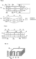
- Fig. 1 is a plan view illustrating the entire piezoelectric pump.
- Fig. 2 is a cross-sectional view taken along line II-II in Fig. 1.
- Fig. 3 is a cross-sectional view taken along line III-III in Fig. 1 .
- This piezoelectric pump 1 includes a pump body 10, a diaphragm 20, a piezoelectric element 21, and a retaining plate 25.
- the pump body 10 is composed of metal or a high-rigidity material such as resin.
- An inlet valve chest 11, a pump chamber 12, and an outlet valve chest 13 are formed between the pump body 10 and the retaining plate 25, and are connected to each other via connecting channels 14 and 15.
- An inlet check valve 16 is disposed in the inlet valve chest 11.
- the inlet check valve 16 allows passage of fluid flowing from an inlet port to the inlet valve chest 11, and blocks fluid flowing in the opposite direction.
- An outlet check valve 17 is disposed in the outlet valve chest 13.
- the outlet check valve 17 allows passage of fluid flowing from the pump chamber 12 to the outlet valve chest 13, and blocks fluid flowing in the opposite direction.
- the pump chamber 12 is a flat space having a depth smaller than the length and the width thereof.
- One of the surfaces of the pump chamber is closed by the diaphragm 20, and the other surfaces are enclosed by the pump body 10 formed of a rigid body.
- the pump body 10 can be composed of metal or resin.
- the pump chamber 12 herein is circular when viewed in plan, the pump chamber can be rectangular.
- the diaphragm 20 formed of an elastic thin plate extends over substantially the entire top surface of the pump body 10, and is fixed between the pump body and the retaining plate 25 by bonding.
- the material of the diaphragm 20 is not specified. However, a thin plate composed of a material with a relatively low Young's modulus such as glass epoxy, resin, and rubber is preferable.
- the piezoelectric element 21 is bonded on the diaphragm 20 in face-to-face relationship.
- the area of a surface of the piezoelectric element 21 perpendicular to a direction along which the piezoelectric element is bent is larger than that of a surface of the pump chamber 12 perpendicular to a direction along which the volume of the pump chamber is changed, and the outer peripheral portion of the piezoelectric element 21 is bonded to the surface of the pump body 10 opposing the piezoelectric element with the diaphragm 20 interposed therebetween. That is, the entire pump chamber 12 is covered with the piezoelectric element 21.
- the diaphragm 20 in this embodiment functions as a gasket for preventing liquid from leaking from the pump chamber 12 and as a protective sheet for preventing the liquid inside the pump chamber 12 from coming into contact with the piezoelectric element 21.
- the retaining plate 25 has an opening 26 formed at a position corresponding to that of the piezoelectric element 21, and the rear surface of the piezoelectric element 21 is left open.
- the piezoelectric pump in the above-described example is provided with the diaphragm 20, this is not meant to exclude a case where the piezoelectric pump is not provided with the diaphragm 20 as a matter of course.
- Only the piezoelectric element 21 can be disposed on substantially the entire top surface of the pump body 10 so as to function as a lid of the pump body. In this case, it is preferable that the thickness of a portion corresponding to the lid of the pump chamber 12, i.e., the piezoelectric element 21, and the thickness of a portion of the pump body 10 corresponding to the bottom of the pump chamber 12 are substantially the same.
- the generated pressure can be maximized even when the piezoelectric pump is small and has a low profile having a thickness of, for example, 1 mm.
- the generated pressure is also affected by the Young's moduli of the portions corresponding to the lid and the bottom of the pump chamber 12.
- the generated pressure can be substantially maximized even when there is a small difference between the Young's moduli of the portions corresponding to the lid and the bottom of the pump chamber 12.
- Figs. 4 to 6 illustrate an example of a specific structure of the piezoelectric element 21.
- the piezoelectric element 21 has a bimorph structure including two laminated piezoelectric layers 21a and 21b composed of a piezoelectric ceramic, and has a quadrangular shape on the whole.
- the piezoelectric ceramic layers 21a and 21b in a state of two green sheets are laminated and pressured with an interlayer electrode 22 serving as a continuous electrode interposed therebetween.
- the laminate is then fired, and polarized after electrodes 23 and 24 are formed on the top and bottom surfaces.
- Fig. 6 illustrates an electrode pattern (a) on the top surface, an electrode pattern (b) of the interlayer electrode, and an electrode pattern (c) on the bottom surface.
- the interlayer electrode 22 has a quadrangular shape that covers substantially the entire piezoelectric layers 21a and 21b except for a narrow edge portion.
- the interlayer electrode 22 extends to outer edges of the piezoelectric layers via a portion of extension 22a, and is connected to an end-face electrode 25 serving as an example of connecting electrodes formed at outer peripheral surfaces of the piezoelectric layers.
- the electrode 23 on the top surface includes a circular central electrode portion 23a, a peripheral electrode portion 23b concentrically surrounding the central electrode portion with a gap interposed therebetween, and an extension electrode portion 23c extending from the central electrode portion 23a to an outer edge of the piezoelectric layer so as to cross the peripheral electrode portion 23b in a radial direction.
- the extension electrode portion 23c is connected to an end-face electrode 26 serving as an example of the connecting electrodes formed at the outer peripheral surfaces of the piezoelectric layers, and the peripheral electrode portion 23b is connected to an end-face electrode 27 serving as an example of the connecting electrodes formed at the outer peripheral surfaces of the piezoelectric layers via an extension 23bl.
- the electrode 24 on the bottom surface includes a circular central electrode portion 24a, a peripheral electrode portion 24b concentrically surrounding the central electrode portion with a gap interposed therebetween, and an extension electrode portion 24c extending from the central electrode portion 24a to an outer edge of the piezoelectric layer so as to cross the peripheral electrode portion 24b in a radial direction.
- the extension electrode portion 24c is formed at a position so as not to face the extension electrode portion 23c of the top-face electrode 23.
- the extension electrode portion 24c is connected to the end-face electrode 27, and the peripheral electrode portion 24b is connected to the end-face electrode 26 via an extension 24b1.
- all the end-face electrodes 25 to 27 are formed at one of the end faces of the piezoelectric element 21.
- the end-face electrodes can be formed at, for example, different end faces as a matter of course.
- the end-face electrode 25 connected to the interlayer electrode 22 is formed between the end-face electrodes 26 and 27.
- the order of formation and the positions of the electrodes can be changed as a matter of course.
- the number of the end-face electrodes 25 to 27 is preferably reduced in view of the ease of wiring.
- additional wiring lines other than the electrodes 25 to 27 can be formed.
- via conductors or through-holes can be used for the connection instead of the end-face electrodes 25 to 27.
- the piezoelectric element 21 has a central area and a peripheral area bent in opposite directions.
- the 23a and 24a, and the peripheral area is defined by the peripheral electrode portions 23b and 24b.
- the interlayer electrode 22 serves as a continuous electrode (solid electrode) extending over the central area and the peripheral area.
- Fig. 7 illustrates an example of electrical wiring during polarization of the piezoelectric element 21.
- the central electrode portion 23a of the top-face electrode 23 and the peripheral electrode portion 24b of the bottom-face electrode 24 are connected to a pole (for example, positive pole) of a DC power source, and the peripheral electrode portion 23b of the top-face electrode 23 and the central electrode portion 24a of the bottom-face electrode 24 are connected to the other pole (for example, negative pole) of the DC power source.
- the interlayer electrode 22 is connected to a ground. With this, the piezoelectric layers 21a and 21b are polarized in directions indicated by arrows P shown in Fig. 7 .
- each of the piezoelectric layers 21a and 21b are polarized opposite to each other in the thickness directions, and corresponding each other in the thickness directions, and corresponding portions in the piezoelectric layers 21a and 21b adjacent to each other are polarized in the same directions.
- the piezoelectric element can be easily polarized as shown in Fig. 7 by applying DC voltages to these three end-face electrodes 25, 26, and 27.
- the extensions 23b1 and 24bl can be extension electrode portions, and the extension electrode portion 23c and the extension 24b1 and the extension electrode portion 24c and the extension 23b1 can extend to corresponding counter corners of the piezoelectric layers 21a and 21b.
- the extension electrode portions are symmetrically formed when the piezoelectric pump is viewed as a whole, and the piezoelectric element can be bent while the balance thereof is maintained compared with the case where all the extension electrode portions are formed at an end face. This leads to a stable drive.
- Figs. 8(a) and 8(b) illustrate an example of electrical wiring and an example of displacement, respectively, during driving of the piezoelectric element 21.
- the interlayer electrode 22 is connected to the ground side of an AC power source, and the central electrode portion 23a and the peripheral electrode portion 23b of the top-face electrode 23 and the central electrode portion 24a and the peripheral electrode portion 24b of the bottom-face electrode 24 are connected to the driving side of the AC power source. With this, electric fields E oriented from the electrodes 23 and 24 on the top and bottom surfaces toward the interlayer electrode 22 as shown in Fig.
- the piezoelectric element can be easily bent by applying AC voltages between the end-face electrode 25 and the end-face electrodes 26 and 27.
- the wiring can be simplified, resulting in a simple driving circuit.
- Fig. 9 illustrates an example of a supporting structure for a piezoelectric element 21 having a neutral area A3 at the outer peripheral portion thereof.
- the piezoelectric element is directly supported by the pump body 10 at the peripheral area A2 thereof.
- the neutral area A3 that is not bent can be formed at the outer peripheral portion of the piezoelectric element 21 when the outer edges of the peripheral electrode portions 23b and 24b are located inside the outer edges of the piezoelectric layers as shown in Fig. 6 .
- the peripheral area A2 can be bent more freely when the piezoelectric element is fixed to the pump body 10 at this neutral area A3.
- the electrical energy loss can be reduced, and separation of the piezoelectric element 21 (diaphragm 20) from the pump body 10 at the interface therebetween and, by extension, liquid leakage can be reduced.
- the diaphragm is not illustrated in Fig. 9 for ease of understanding, the same applies to the case where the diaphragm is bonded to the entire surface of the piezoelectric element 21.
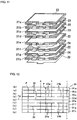
- Figs. 10 to 13 illustrate a piezoelectric element according to a second embodiment.
- This piezoelectric element 30 is a laminate including a plurality of (herein eight) piezoelectric layers 31a to 31h each having an electrode of one of the three electrode patterns (a) to (c) shown in Fig. 6 .
- the order of the electrode patterns is (b), (a), (b), (a), (b), (c), (b), (c), and (b) from the top. That is, continuous electrodes and split electrodes are alternately disposed in a direction along which the layers are stacked.
- the piezoelectric layers 31a to 31h are polarized as shown in Fig. 12 . That is, the polarization direction in the central area and that in the peripheral area of each of the piezoelectric layers 31a to 31h are opposite to each other.
- the piezoelectric layers 31a to 31h are piezoelectric portion whose expansion/contraction directions differ from each other and the border is defined as Fp
- two piezoelectric layers adjacent to each other in the thickness direction in the upper four piezoelectric layers 31a to 31d (first piezoelectric portion) located above the border Fp are polarized in opposite directions.
- two piezoelectric layers adjacent to each other in the thickness direction in the lower four piezoelectric layers 31e to 31h (second piezoelectric portion) located below the border Fp are polarized in opposite directions. Only the polarization directions in the two piezoelectric layers 31d and 31e that are located at a central portion in the thickness direction and are adjacent to each other having the border Fp interposed therebetween are the same.
- continuous electrodes 22 are connected to a ground, a positive DC voltage is applied to central electrode portions 23a of the upper four layers and peripheral electrode portions 24b of the lower four layers, and a negative DC voltage is applied to peripheral electrode portions 23b of the upper four layers and central electrode portions 24a of the lower four layers as shown in Fig. 12 .
- the piezoelectric layers can be polarized in directions shown in Fig. 12 by connecting an end-face electrode 25 to the ground, applying a positive DC voltage to an end-face electrode 26, and applying a negative DC to an end-face electrode 26, and applying a negative DC voltage to an end-face electrode 27.
- alternating voltages are applied to the piezoelectric element 30 polarized as above between the interlayer electrode 22 and all the central electrode portions 23a and 24a and the peripheral electrode portions 23b and 24b as shown in Fig. 13 .
- the central areas and the peripheral areas of the piezoelectric layers are expanded or contracted as indicated by double-headed arrows, and the central area and the peripheral area of the piezoelectric element 30 can be bent in opposite directions.
- the piezoelectric layers are expanded or contracted in opposite directions from the state shown in Fig. 13 .
- Figs. 14 to 16 illustrate another example of a specific structure of a piezoelectric element.
- This piezoelectric element 40 includes two laminated piezoelectric layers 41a and 41b composed of a piezoelectric ceramic as that in the first embodiment. That is, the piezoelectric ceramic layers 41a and 41b in a state of two green sheets are laminated and pressured with an interlayer electrode 42 interposed therebetween. The laminate is then fired, and polarized after electrodes 43 and 44 are formed on the top and bottom surfaces.
- Fig. 16 illustrates an electrode pattern (a) on the top surface, an electrode pattern (b) of the interlayer electrode, and an electrode pattern (c) on the bottom surface.
- the interlayer electrode 42 includes a circular continuous electrode portion 42a and dummy electrode portions 42b formed at four corners around the continuous electrode portion.
- the circular continuous electrode layers via an extension 42a1, and is connected to an end-face electrode 45 formed at outer peripheral surfaces of the piezoelectric layers.
- the dummy electrode portions 42b are isolated, and are not connected to other electrodes.
- the electrode 43 on the top surface includes a circular central electrode portion 43a, a peripheral electrode portion 43b surrounding the central electrode portion with a gap interposed therebetween, and an extension electrode portion 43c extending from the central electrode portion 43a to an outer edge of the piezoelectric layer so as to cross the peripheral electrode portion 43b in a radial direction.
- the extension electrode portion 43c is connected to an end-face electrode 46 formed at the outer peripheral surfaces of the piezoelectric layers, and the peripheral electrode portion 43b is connected to an end-face electrode 47 formed at the outer peripheral surfaces of the piezoelectric layers via an extension 43b1.
- the electrode 44 on the bottom surface includes a circular central electrode portion 44a, a peripheral electrode portion 44b surrounding the central electrode portion with a gap interposed therebetween, and an extension electrode portion 44c extending from the central electrode portion 44a to an outer edge of the piezoelectric layer so as to cross the peripheral electrode portion 44b in a radial direction.
- the extension electrode portion 44c and the extension electrode portion 43c of the top-face the extension electrode portion 43c of the top-face electrode 43 are formed at different positions in circumferential direction.
- the extension electrode portion 44c is connected to the end-face electrode 47, and the peripheral electrode portion 44b is connected to the end-face electrode 46 via an extension 44b1.
- the central electrode portions 43a and 44a are formed so as to be concentric with the continuous electrode portion 42a. The positions of the end-face electrodes 45 to 47 can be arbitrarily changed.
- the central area of the piezoelectric element 40 is defined by the central electrode portions 43a and 44a, and the peripheral area is defined by the outer edge of the continuous electrode portion 42a and the inner edges of the peripheral electrode portions 43b and 44b.
- a neutral area that is not bent spontaneously is formed at the outer peripheral portion of the piezoelectric element 40.
- the electrodes 42, 43, and 44 cover the entire piezoelectric layers since the peripheral electrode portion 43b of the top-face electrode 43 and the peripheral electrode portion 44b of the bottom-face electrode 44 extend to the vicinity of the outer portions of the piezoelectric layers and the interlayer electrode 42 includes the dummy electrode portions 42b that cover the outer edges of the piezoelectric layers.
- the central electrode portion 43a of the top-face electrode 43 and the peripheral electrode portion 44b of the bottom-face electrode 44 are connected to each other via the end-face electrode 46
- the peripheral electrode portion 43b of the top-face electrode 43 and the central electrode portion 44a of the bottom-face electrode 44 are connected to each other via the end-face electrode 47
- the continuous electrode portion 42a is connected to the end-face electrode 45. Therefore, the piezoelectric layers can be polarized as shown in Fig. 7 by connecting the end-face electrode 46 to one of the poles of a DC power source, connecting the end-face electrode 47 to the other pole of the DC power source, and connecting the end-face electrode 45 to a ground during polarization. Moreover, a displacement as shown in Fig.
- the piezoelectric element 40 can be easily polarized and driven without changing the shapes of the electrodes by electrically connecting the three end-face electrodes 45, 46, and 47 in an appropriate manner.
- a piezoelectric element 60 shown in Fig. 17 is a laminate including three piezoelectric layers 61a to 61c, and differs from that in the embodiment shown in Figs. 8(a) and 8(b) in that the piezoelectric element 60 includes the intermediate layer 61b for relieving stress at a central portion in the thickness direction. Electrodes on the top and bottom surfaces are split into central electrode portions 62a and 63a and peripheral electrode portions 62b and 63b, respectively, and continuous electrodes 64 and 65 extending over the central area and the peripheral area are disposed between the layers. The continuous electrodes 64 and 65 are disposed on either side of the intermediate layer 61b. In this example, the intermediate layer 61b is not polarized, and not expanded or contracted.
- one end of an AC power source 66 is connected to the split electrode portions 62a, 62b, 63a, and 63b and the other end is connected to the continuous electrodes 64 and 65 during driving.
- the central area can be convexed in an upward direction
- the peripheral area can be concaved in a downward direction.
- a piezoelectric element 70 shown in Fig. 18 is a laminate including five piezoelectric layers 71a to 71e.
- the piezoelectric element 70 includes the intermediate layer 71c for relieving stress at a central portion in the thickness direction.
- the central portion and the peripheral portion in each layer are polarized in opposite directions, and the directions of polarization in the two piezoelectric layers 71b and 71d adjacent to the middle position in the thickness direction are the same.
- the directions of polarization in the outer piezoelectric layers 71a and 71e are opposite to those in the piezoelectric layers 71b and 71d, respectively, adjacent to each other in the thickness direction.
- electrodes 72 and 73 disposed on either side of the intermediate layer 71c and disposed on either side of the intermediate layer 71c and electrodes 74 and 75 disposed on the top and bottom surfaces, respectively, are continuous electrodes, and other interlayer electrode portions 76a, 76b, 77a, and 77b are split electrodes split so as to correspond to the central portion and the peripheral portion. That is, the continuous electrodes and the split electrodes are alternatively disposed in the layer laminating direction. As shown in Fig. 18 , one end of an AC power source 78 is connected to the split electrode portions 76a, 76b, 77a, and 77b and the other end is connected to the continuous electrodes 72, 73, 74, and 75 during driving.
- the central area can be convexed in an upward direction, and the peripheral area can be concaved in a downward direction. Also in this case, short-circuits caused by migration can be prevented since the potentials of the central electrode portion 76a and the peripheral electrode portion 76b that are adjacent to each other in the same plane are the same and the potentials of the central electrode portion 77a and the peripheral electrode portion 77b that are adjacent to each other in the same plane are the same, and the driving circuit can be simplified.
- the piezoelectric element shown in Fig. 17 includes three piezoelectric layers and the piezoelectric element shown in Fig. 18 includes five piezoelectric layers. However, a plurality of piezoelectric layers can be further laminated on the outermost layers, and the continuous electrodes and the split electrodes can be alternatively formed.
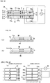
- Figs. 19(a) and 19(b) illustrate a diaphragm 80 and a piezoelectric element 90 fixed to one side of the diaphragm used for a piezoelectric pump according to an example.
- the piezoelectric element 90 is of the bimorph type, and can be uniformly bent unlike a piezoelectric element in which the central area and the peripheral area are bent in opposite directions, such as those in the first to fifth embodiments.
- the displacement can be maximized by, for example, setting an inversion plane Fp at which the expansion/contraction directions are inverted at the middle position in the thickness direction as shown in Fig. 19(a) .
- the inversion plane is set at the middle position in the thickness direction of the piezoelectric element 90 in the case where the piezoelectric element 90 of the bimorph type is bonded to the diaphragm 80 functioning like an elastic a neutral plane Fd of the entire diaphragm is shifted from the middle position Fp in the thickness direction of the piezoelectric element to the diaphragm 80.
- the inversion plane Fp of the piezoelectric element is formed at a position shifted from the middle position in the thickness direction to the diaphragm as shown in Fig. 19(b) such that the neutral plane Fd of the entire diaphragm and the inversion plane Fp of the piezoelectric element correspond to each other.
- Figs. 20(a) and 20(b) illustrate a method for matching the inversion plane Fp of the piezoelectric element 90 with the neutral plane Fd of the entire diaphragm by changing the number of lamination layers at either side of the inversion plane Fp of the piezoelectric element 90.
- the piezoelectric element 90 in this example is a laminate including a plurality of piezoelectric layers 90a to 90d having electrodes 91b to 91d interposed therebetween, and electrodes 91a and 91e are formed on the top and bottom surfaces, respectively.
- the diaphragm 80 is bonded to the bottom surface of the piezoelectric element 90.
- Fig. 20(a) illustrates voltage application during polarization.
- Polarities P indicated by arrows can be obtained by, for example, applying DC voltages such that the electrodes 91a and 91c are at a negative potential, the electrode 91e is at a positive potential, and the electrodes 91b and 91d are at a ground potential.
- Fig. 20(b) illustrates voltage application during driving.
- the upper three layers 90a to 90c and the lower one layer 90d expand or contract in opposite directions.
- the inversion plane Fp is located at the position of the surface of the second electrode 91d from the bottom.
- the number of piezoelectric layers to be laminated in the piezoelectric element 90 can be arbitrarily selected.
- Figs. 21(a) and 21(b) illustrate a method for changing the thickness of a piezoelectric layer at either side of the inversion plane Fp of a piezoelectric element 92.
- the piezoelectric element 92 in this example is a laminate including two piezoelectric layers 92a and 92b with different thicknesses having an electrode 93b interposed therebetween, and electrodes 93a and 93c are formed on the top and bottom surfaces, respectively.
- Fig. 21(a) illustrates voltage application during polarization
- Fig. 21(b) illustrates voltage application during driving.
- the upper piezoelectric layer 92a has a thickness larger than that of the lower piezoelectric layer 92b, and different voltages depending on the thicknesses are applied during polarization.
- Voltage reducing means 99 such as a polarization.
- Voltage reducing means 99 such as a resistance is connected so as to reduce the potential of the bottom-face electrode 93c compared with that of the top-face electrode 93a during driving.
- the inversion plane Fp is located at the position of the surface of the interlayer electrode 93b.
- Figs. 22(a) and 22(b) illustrate a method for matching the inversion plane of the piezoelectric element with the neutral plane of the entire diaphragm by changing the strength of driving electric fields applied to upper and lower piezoelectric layers in a piezoelectric element 94.
- the piezoelectric element 94 is a laminate including two piezoelectric layers 94a and 94b with the same thickness having an electrode 95b interposed therebetween, and electrodes 95a and 95c are formed on the top and bottom surfaces, respectively.
- Fig. 22(a) illustrates voltage application during polarization
- Fig. 22(b) illustrates voltage application during driving. As shown in Fig.
- the field strength of the upper piezoelectric layer 94a is increased compared with that of the lower piezoelectric layer 94b using the voltage reducing means 99.
- the expansion/contraction stress imposed on the upper piezoelectric layer 94a is higher than that on the lower piezoelectric element alone is located at a position shifted from the inversion plane Fp to the opposite side of the diaphragm 80.
- the inversion plane Fp can match the neutral plane of the entire diaphragm.
- the ratio of the field strength of the upper piezoelectric layer 94a to that of the lower piezoelectric layer 94b during driving can be arbitrarily set depending on the Young's modulus and the thickness of the diaphragm 80. When a plurality of piezoelectric layers are laminated in this case, the thickness of the piezoelectric layers at either side of the inversion plane Fp can be changed.
- Figs. 23(a) and 23(b) illustrate a method for matching the inversion plane of the piezoelectric element with the neutral plane of the entire diaphragm by changing the degrees P of polarization of upper and lower piezoelectric layers in a piezoelectric element 96.
- the piezoelectric element 96 is a laminate including two piezoelectric layers 96a and 96b with the same thickness having an electrode 97b interposed therebetween, and electrodes 97a and 97c are formed on the top and bottom surfaces, respectively.
- FIG. 23(a) illustrates voltage application during polarization performed such that the degree P1 of polarization of the upper piezoelectric layer 96a is higher than the degree P2 of polarization of the lower piezoelectric layer 96b.
- Voltage reducing means 99 is not required during driving as Voltage reducing means 99 is not required during driving as shown in Fig. 23(b) since the same electric fields are applied to the upper piezoelectric layer 96a and the lower piezoelectric layer 96b.
- the expansion/contraction stress imposed on the upper piezoelectric layer 96a is higher than that on the lower piezoelectric layer 96b, and the neutral plane of the piezoelectric element alone is located at a position shifted from the inversion plane to the opposite side of the diaphragm 80.
- the inversion plane Fp can match the neutral plane of the entire diaphragm.
- the effect of matching the inversion plane Fp of the piezoelectric element 90 with the neutral plane Fd of the entire diaphragm as described above becomes marked as the rigidity and the thickness of the diaphragm are increased.
- the material of the diaphragm can be as soft and thin as possible so as not to interfere with the motion of the piezoelectric element.
- a diaphragm with high rigidity is suitable when, for example, it is necessary to increase the generated pressure of the pump or to increase the driving frequency. In this case, matching of the inversion plane of the piezoelectric element with the neutral plane of the entire diaphragm produces a significant effect.
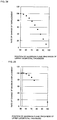
- Position of inversion plane % thickness d 1 of upper layer / total thickness D That is, 50% indicates that the inversion plane is located at the middle position of the bimorph piezoelectric element. The value is increased from 50% as the thickness of the upper layer is further increased. The value becomes 100% when only the upper layer exists (no lower layer exists).
- Fig. 24 illustrates a rate of change of displacement when the thickness d1 of the upper layer of a bimorph piezoelectric element having a total thickness D of 0.30 mm is gradually increased from a state where the thicknesses of the upper and lower layers are both 0.15 mm. 50% indicates that there is no difference between the thicknesses of the upper and lower layers each having a thickness of 0.15 mm, and 100% indicates that only the upper layer having a thickness of 0.30 mm exists. As is clear from the drawing, the displacement is reduced as the thickness d1 of the upper layer is increased.
- Fig. 25 illustrates a rate of change of displacement when the thickness d1 of the upper layer of a bimorph piezoelectric element having a total thickness D of 0.30 mm and bonded to a glass epoxy board having a thickness of 0.1 mm is gradually increased.
- the thickness d1 of the upper layer with respect to the total thickness D is approximately 52.5%, the rate of change of the displacement reaches a peak of 100.61%.
- the displacement is increased.
- Fig. 26 illustrates a rate of change of displacement when the thickness d1 of the upper layer of a bimorph piezoelectric element having a total thickness D of 0.30 mm and bonded to a SUS board having a thickness of 0.1 mm is gradually increased.
- the displacement reaches a peak when the thickness d1 of the upper layer with respect to the total thickness D is 75%.
- the rate of change of the displacement reaches 129.18% by matching the inversion plane with the neutral plane, and a marked increase of +30% in the displacement can be achieved.
- heat generation can also be prevented.
- the present invention is not limited to the above-described embodiments, and various modifications are possible.
- the structure in which the inversion plane of the piezoelectric element matches the neutral plane of the entire diaphragm is applied to an example in which a piezoelectric element of the typical bimorph type is bonded to a diaphragm.
- the structure can also be applied to examples in which a piezoelectric element whose central area and peripheral area are bent in opposite directions is bonded to a diaphragm, such as those in the first to fifth embodiments.
- the piezoelectric pump according to the present invention is compact and low-profiled, the piezoelectric pump is useful for fuel supply to fuel cells for, for example, portable devices, and for, for example, circulation of cooling water.
- the application is not limited to these.
Landscapes
- Engineering & Computer Science (AREA)
- Mechanical Engineering (AREA)
- General Engineering & Computer Science (AREA)
- Manufacturing & Machinery (AREA)
- Reciprocating Pumps (AREA)
- General Electrical Machinery Utilizing Piezoelectricity, Electrostriction Or Magnetostriction (AREA)
Claims (7)
- Eine piezoelektrische Pumpe, die folgende Merkmale aufweist:einen Pumpenkörper (10) mit einer Pumpenkammer (12); undein piezoelektrisches Element (21; 30; 40; 60; 70), das von dem Pumpenkörper (10) dahingehend gestützt wird, die Pumpenkammer (12) zu schließen und sich durch das Anlegen einer Spannung zu biegen, um das Volumen der Pumpenkammer (12) zu ändern, wobei das piezoelektrische Element (21; 30; 40; 60; 70) einen Mittelbereich (A1) und einen Randbereich (A2) aufweist, der den Mittelbereich (A1) an einem Abschnitt umgibt, der der Pumpenkammer (12) entspricht, wobei der Mittelbereich (A1) und der Randbereich (A2) gemäß Treiberspannungen, die an das piezoelektrische Element (21; 30; 40; 60; 70) angelegt werden, in gegengesetzten Richtungen gebogen werden,wobei das piezoelektrische Element (21; 30; 40; 60; 70) durch Laminieren einer Mehrzahl von piezoelektrischen Schichten (21a-b; 31a-h; 41a-b; 61a-c; 71a-e) mit dazwischen eingefügten Elektroden (22-24; 42-44; 62-65; 72-77), durch Brennen des Laminats und durch Polarisieren des Laminats gebildet wird,dadurch gekennzeichnet, dassder Mittelbereich (A1) und der Randbereich (A2) jede der piezoelektrischen Schichten (21a-b; 31a-h; 41a-b; 61a-c; 71a-e) zueinander in einer Dickenrichtung des Laminats entgegengesetzt polarisiert sind,die Elektroden (22-24; 42-44; 62-65; 72-77) derart gebildet sind, dass treibende elektrische Felder, die in derselben Richtung in der Dickenrichtung ausgerichtet sind, an den Mittelbereich (A1) und den Randbereich (A2) jeder der piezoelektrischen Schichten (21a-b; 31a-h; 41a-b; 61a-c; 71a-e) angelegt werden, undTreiberspannungen bei demselben Potenzial an die Elektroden (22-24; 42-44; 62-65; 72-77) angelegt werden, die in den gleichen Ebenen der piezoelektrischen Schichten (21a-b; 31a-h; 41a-b; 61a-c; 71a-e) gebildet sind,die Elektroden (22-24; 42-44; 62-65; 72-77) geteilte Elektroden, die dahingehend geteilt sind, dem Mittelbereich (A1) und dem Randbereich (A2) zu entsprechen, und fortlaufende Elektroden umfassen, die sich über den Mittelbereich (A1) und den Randbereich (A2) erstrecken, unddie geteilten Elektroden und die fortlaufenden Elektroden abwechselnd in einer Richtung angeordnet sind, entlang der die piezoelektrischen Schichten (21a-b; 31a-h; 41a-b; 61a-c; 71a-e) laminiert sind.
- Die piezoelektrische Pumpe gemäß Anspruch 1, bei der zwei oder mehr fortlaufende Elektroden zwischen zwei in der Schichtlaminierrichtung benachbarten geteilten Elektroden angeordnet sind, und eine Zwischenschicht, die nicht spontan gebogen wird, zwischen den zwei oder mehr fortlaufenden Elektroden angeordnet ist.
- Die piezoelektrische Pumpe gemäß Anspruch 1 oder 2, bei der die geteilten Elektroden jeweils einen Mittelelektrodenabschnitt, der an einer dem Mittelbereich (A1) entsprechenden Position gebildet ist, einen Randelektrodenabschnitt, der an einer dem Randbereich (A2) entsprechenden Position gebildet ist und den Mittelelektrodenabschnitt mit einem dazwischen eingefügten Zwischenraum umgibt, und einen Erweiterungselektrodenabschnitt umfasst, der sich von dem Mittelelektrodenabschnitt zu dem äußeren Rand der piezoelektrischen Schichten erstreckt, um den Randelektrodenabschnitt zu überqueren,
das piezoelektrische Element (21; 30; 40; 60; 70) einen ersten piezoelektrischen Abschnitt und einen zweiten piezoelektrischen Abschnitt umfasst, die in der Schichtlaminierrichtung angeordnet sind, wobei sich die piezoelektrischen Abschnitte in entgegengesetzten Richtungen ausdehnen oder zusammenziehen, wenn die Treiberspannungen angelegt werden, und
das piezoelektrische Element (21; 30; 40; 60; 70) eine erste Verbindungselektrode und eine zweite Verbindungselektrode umfasst, die an dem äußeren Rand desselben gebildet sind, wobei die erste Verbindungselektrode die Erweiterungselektrodenabschnitte, die sich von den zwischen den piezoelektrischen Schichten in dem ersten piezoelektrischen Abschnitt gebildeten Mittelelektrodenabschnitten erstrecken, und die zwischen den piezoelektrischen Schichten in dem zweiten piezoelektrischen Abschnitt gebildeten Randelektrodenabschnitte verbindet, wobei die zweite Verbindungselektrode die zwischen den piezoelektrischen Schichten in dem ersten piezoelektrischen Abschnitt gebildeten Randelektrodenabschnitte und die Erweiterungselektrodenabschnitte verbindet, die sich von den zwischen den piezoelektrischen Schichten in dem zweiten piezoelektrischen Abschnitt gebildeten Mittelelektrodenabschnitten erstrecken. - Die piezoelektrische Pumpe gemäß Anspruch 3, bei der der erste piezoelektrische Abschnitt und der zweite piezoelektrische Abschnitt jeweils eine Mehrzahl von laminierten piezoelektrischen Schichten umfassen,
die zwischen den piezoelektrischen Schichten in dem ersten piezoelektrischen Abschnitt gebildeten Mittelelektrodenabschnitte miteinander verbunden sind und die zwischen den piezoelektrischen Schichten in dem ersten piezoelektrischen Abschnitt gebildeten Randelektrodenabschnitte miteinander verbunden sind, und
die zwischen den piezoelektrischen Schichten in dem zweiten piezoelektrischen Abschnitt gebildeten Mittelelektrodenabschnitte miteinander verbunden sind und die zwischen den piezoelektrischen Schichten in dem zweiten piezoelektrischen Abschnitt gebildeten Randelektrodenabschnitte miteinander verbunden sind. - Die piezoelektrische Pumpe gemäß einem der Ansprüche 1 bis 4, bei der das piezoelektrische Element (21; 30; 40; 60; 70) einen Neutralbereich, der nicht spontan gebogen wird, aufweist, welcher außerhalb des Randbereichs (A2) benachbart zu dem äußeren Rand gebildet ist, und von dem Pumpenkörper (10) an dem Neutralbereich getragen wird.
- Die piezoelektrische Pumpe gemäß einem der Ansprüche 1 bis 5, bei der
die piezoelektrischen Schichten rechtwinklig sind,
die Mittelelektrodenabschnitte kreisförmig sind, und
die Randelektrodenabschnitte ringförmig konzentrisch mit den Mittelelektrodenabschnitten sind. - Die piezoelektrische Pumpe gemäß einem der Ansprüche 1 bis 6, bei der eine Membran zum Trennen des piezoelektrische Elements (21; 30; 40; 60; 70) von der Pumpenkammer (12) an einer Oberfläche des piezoelektrische Elements (21; 30; 40; 60; 70) benachbart zu der Pumpenkammer (12) in einer zugewandten Beziehung angehaftet ist.
Priority Applications (1)
| Application Number | Priority Date | Filing Date | Title |
|---|---|---|---|
| EP12196133.8A EP2573396B1 (de) | 2006-07-11 | 2007-07-09 | Piezoelektrische Pumpe |
Applications Claiming Priority (2)
| Application Number | Priority Date | Filing Date | Title |
|---|---|---|---|
| JP2006190176 | 2006-07-11 | ||
| PCT/JP2007/063645 WO2008007634A1 (en) | 2006-07-11 | 2007-07-09 | Piezoelectric pump |
Related Child Applications (2)
| Application Number | Title | Priority Date | Filing Date |
|---|---|---|---|
| EP12196133.8A Division-Into EP2573396B1 (de) | 2006-07-11 | 2007-07-09 | Piezoelektrische Pumpe |
| EP12196133.8A Division EP2573396B1 (de) | 2006-07-11 | 2007-07-09 | Piezoelektrische Pumpe |
Publications (3)
| Publication Number | Publication Date |
|---|---|
| EP2039934A1 EP2039934A1 (de) | 2009-03-25 |
| EP2039934A4 EP2039934A4 (de) | 2012-06-13 |
| EP2039934B1 true EP2039934B1 (de) | 2018-10-17 |
Family
ID=38923193
Family Applications (2)
| Application Number | Title | Priority Date | Filing Date |
|---|---|---|---|
| EP12196133.8A Active EP2573396B1 (de) | 2006-07-11 | 2007-07-09 | Piezoelektrische Pumpe |
| EP07768369.6A Active EP2039934B1 (de) | 2006-07-11 | 2007-07-09 | Piezoelektrische pumpe |
Family Applications Before (1)
| Application Number | Title | Priority Date | Filing Date |
|---|---|---|---|
| EP12196133.8A Active EP2573396B1 (de) | 2006-07-11 | 2007-07-09 | Piezoelektrische Pumpe |
Country Status (6)
| Country | Link |
|---|---|
| US (1) | US8162629B2 (de) |
| EP (2) | EP2573396B1 (de) |
| JP (2) | JP4911171B2 (de) |
| KR (1) | KR101070944B1 (de) |
| CN (2) | CN101490418B (de) |
| WO (1) | WO2008007634A1 (de) |
Families Citing this family (25)
| Publication number | Priority date | Publication date | Assignee | Title |
|---|---|---|---|---|
| CN101622451B (zh) | 2007-12-03 | 2011-05-11 | 株式会社村田制作所 | 压电泵 |
| JP5234008B2 (ja) | 2008-04-17 | 2013-07-10 | 株式会社村田製作所 | 積層型圧電素子及び圧電ポンプ |
| US8061820B2 (en) * | 2009-02-19 | 2011-11-22 | Fujifilm Corporation | Ring electrode for fluid ejection |
| JP2010251726A (ja) * | 2009-03-27 | 2010-11-04 | Ngk Insulators Ltd | 圧電アクチュエータの製造方法 |
| EP2436961B1 (de) | 2009-05-25 | 2020-09-30 | Murata Manufacturing Co., Ltd. | Ventil, flüssigkeitsvorrichtung und flüssigkeitszufuhrvorrichtung |
| EP2682995A4 (de) * | 2011-03-01 | 2014-10-22 | Murata Manufacturing Co | Piezoelektrisches element und piezoelektrische vorrichtung damit |
| KR101190119B1 (ko) | 2011-03-24 | 2012-10-12 | 한국기계연구원 | 커팅 분사 방식의 가압 면적 변위 확대형 디스펜서 |
| JP5708167B2 (ja) * | 2011-04-06 | 2015-04-30 | コニカミノルタ株式会社 | 超音波探触子及び超音波診断装置 |
| EP2764556B1 (de) * | 2011-10-05 | 2016-06-29 | Ross Bird | Autonome transformatoren in form einer lattenkonstruktion |
| CN103182354A (zh) * | 2011-12-30 | 2013-07-03 | 广州市番禺奥迪威电子有限公司 | 一种低压驱动超声波雾化片 |
| JP5974493B2 (ja) * | 2012-01-18 | 2016-08-23 | 株式会社村田製作所 | 圧電ポンプ、圧電ポンプの製造方法 |
| US8904876B2 (en) * | 2012-09-29 | 2014-12-09 | Stryker Corporation | Flexible piezocapacitive and piezoresistive force and pressure sensors |
| WO2015114849A1 (ja) * | 2014-01-30 | 2015-08-06 | 京セラ株式会社 | 圧電素子およびこれを備えた圧電振動装置、携帯端末、音響発生器、音響発生装置、電子機器 |
| JP6173938B2 (ja) * | 2014-02-05 | 2017-08-02 | 株式会社東芝 | 圧電ポンプ |
| EP3604810B1 (de) * | 2014-02-21 | 2023-06-28 | Murata Manufacturing Co., Ltd. | Fluidregelungsvorrichtung und pumpe |
| JP6518417B2 (ja) * | 2014-09-01 | 2019-05-22 | 東芝テック株式会社 | 液体循環装置 |
| JP2017007108A (ja) * | 2015-06-17 | 2017-01-12 | 東芝テック株式会社 | インク循環装置及びインクジェット記録装置 |
| DE102015116409A1 (de) * | 2015-09-28 | 2017-03-30 | Fraunhofer-Gesellschaft zur Förderung der angewandten Forschung e.V. | Verbundkörper mit mindestens einer Funktionskomponente und ein Verfahren zur Herstellung des Verbundkörpers |
| CN105736330A (zh) * | 2016-02-02 | 2016-07-06 | 河南工业大学 | 医用微量注射并联微泵 |
| EP3623059B1 (de) | 2017-05-12 | 2024-02-28 | Murata Manufacturing Co., Ltd. | Vibrationsvorrichtung |
| FR3077162B1 (fr) * | 2018-01-22 | 2020-02-07 | Commissariat A L'energie Atomique Et Aux Energies Alternatives | Transducteur piezoelectrique |
| GB201803177D0 (en) * | 2018-02-27 | 2018-04-11 | 3C Project Man Limited | Droplet ejector |
| JP7055950B2 (ja) * | 2018-02-28 | 2022-04-19 | 太陽誘電株式会社 | 振動発生装置及び電子機器 |
| CN109390462B (zh) * | 2018-09-11 | 2020-12-22 | 北京大学 | 准切变模式多层共烧压电致动器及其多层共烧制备方法 |
| JP7349090B2 (ja) * | 2019-05-21 | 2023-09-22 | 日清紡マイクロデバイス株式会社 | 圧電素子 |
Family Cites Families (17)
| Publication number | Priority date | Publication date | Assignee | Title |
|---|---|---|---|---|
| JPS6130974A (ja) * | 1984-07-23 | 1986-02-13 | Nippon Telegr & Teleph Corp <Ntt> | 圧電アクチユエ−タ |
| CA1225694A (en) * | 1983-12-09 | 1987-08-18 | Nippon Telegraph And Telephone Corporation | Piezoelectric actuator using bimorph element |
| JPS6128776A (ja) * | 1984-07-17 | 1986-02-08 | Matsushita Electric Ind Co Ltd | ポンプ |
| JPS6130947A (ja) * | 1984-07-20 | 1986-02-13 | Matsushita Electric Works Ltd | 整流子モ−タ |
| DE3618106A1 (de) | 1986-05-30 | 1987-12-03 | Siemens Ag | Piezoelektrisch betriebene fluidpumpe |
| JPH0317184A (ja) * | 1989-06-14 | 1991-01-25 | Tsuchiya Rubber Kk | 土壌組成物 |
| JPH0354383A (ja) * | 1989-07-20 | 1991-03-08 | Olympus Optical Co Ltd | 圧電式ポンプ |
| JPH03134271A (ja) * | 1989-10-17 | 1991-06-07 | Seiko Epson Corp | 微量吐出装置 |
| JPH03171784A (ja) | 1989-11-30 | 1991-07-25 | Toshiba Corp | バイモルフ素子 |
| JPH03171750A (ja) | 1989-11-30 | 1991-07-25 | Toshiba Corp | 微小移動機構 |
| JP3428773B2 (ja) * | 1995-04-21 | 2003-07-22 | 松下電器産業株式会社 | バイモルフ圧電素子とその製造方法 |
| US6597084B2 (en) * | 2001-01-05 | 2003-07-22 | The Hong Kong Polytechnic University | Ring-shaped piezoelectric transformer having an inner and outer electrode |
| JP3642026B2 (ja) | 2001-01-12 | 2005-04-27 | 株式会社村田製作所 | 加速度センサおよびその製造方法 |
| US6812623B2 (en) * | 2001-09-28 | 2004-11-02 | Matsushita Electric Industrial Co., Ltd. | Piezoelectric transformer |
| JP4096721B2 (ja) | 2001-12-06 | 2008-06-04 | ブラザー工業株式会社 | 圧電アクチュエータ、流体移送装置及びインクジェットヘッド |
| US6869275B2 (en) * | 2002-02-14 | 2005-03-22 | Philip Morris Usa Inc. | Piezoelectrically driven fluids pump and piezoelectric fluid valve |
| JP4419790B2 (ja) * | 2004-10-20 | 2010-02-24 | パナソニック電工株式会社 | 圧電ダイヤフラムポンプ |
-
2007
- 2007-07-09 CN CN2007800263931A patent/CN101490418B/zh active Active
- 2007-07-09 KR KR1020097000454A patent/KR101070944B1/ko active Active
- 2007-07-09 EP EP12196133.8A patent/EP2573396B1/de active Active
- 2007-07-09 JP JP2008524784A patent/JP4911171B2/ja active Active
- 2007-07-09 CN CN2010105739134A patent/CN102094796B/zh active Active
- 2007-07-09 WO PCT/JP2007/063645 patent/WO2008007634A1/ja not_active Ceased
- 2007-07-09 EP EP07768369.6A patent/EP2039934B1/de active Active
-
2008
- 2008-12-24 JP JP2008327569A patent/JP4803249B2/ja active Active
-
2009
- 2009-01-09 US US12/351,158 patent/US8162629B2/en active Active
Non-Patent Citations (1)
| Title |
|---|
| None * |
Also Published As
| Publication number | Publication date |
|---|---|
| CN101490418B (zh) | 2011-04-20 |
| WO2008007634A1 (en) | 2008-01-17 |
| EP2039934A1 (de) | 2009-03-25 |
| JPWO2008007634A1 (ja) | 2009-12-10 |
| US8162629B2 (en) | 2012-04-24 |
| EP2039934A4 (de) | 2012-06-13 |
| CN101490418A (zh) | 2009-07-22 |
| JP4803249B2 (ja) | 2011-10-26 |
| EP2573396A2 (de) | 2013-03-27 |
| JP2009063002A (ja) | 2009-03-26 |
| EP2573396B1 (de) | 2017-12-20 |
| US20090142209A1 (en) | 2009-06-04 |
| KR20090020686A (ko) | 2009-02-26 |
| JP4911171B2 (ja) | 2012-04-04 |
| KR101070944B1 (ko) | 2011-10-06 |
| CN102094796A (zh) | 2011-06-15 |
| EP2573396A3 (de) | 2013-04-10 |
| CN102094796B (zh) | 2013-02-13 |
Similar Documents
| Publication | Publication Date | Title |
|---|---|---|
| EP2039934B1 (de) | Piezoelektrische pumpe | |
| US20080170951A1 (en) | Piezoelectric pump | |
| US20100239444A1 (en) | Layered piezoelectric element and piezoelectric pump | |
| JP4840505B2 (ja) | 圧電ポンプ | |
| CN108050051B (zh) | 流体控制装置以及泵 | |
| JP4858546B2 (ja) | 圧電バルブ | |
| EP2123913A1 (de) | Flüssigkeitstransportvorrichtung | |
| US20080038125A1 (en) | Piezoelectric pump and piezoelectric vibrator | |
| JP4976157B2 (ja) | 圧電ポンプ及び圧電振動子 | |
| JP2010242501A (ja) | 圧電ポンプ | |
| CN114822253B (zh) | 仿形治具及贴合装置 | |
| JP2009108715A (ja) | 圧電ポンプ | |
| JPH0354383A (ja) | 圧電式ポンプ | |
| US20070071615A1 (en) | Diaphragm pump | |
| US20080199331A1 (en) | Piezoelectric pump | |
| JP4940042B2 (ja) | 圧電ポンプ | |
| CN118775224A (zh) | 一种基于铁电PZT薄膜d33模式的MEMS压电微泵 | |
| JP2006204099A (ja) | 電歪ポリマーアクチュエータ | |
| JP2006132476A (ja) | 圧電気体ポンプ |
Legal Events
| Date | Code | Title | Description |
|---|---|---|---|
| PUAI | Public reference made under article 153(3) epc to a published international application that has entered the european phase |
Free format text: ORIGINAL CODE: 0009012 |
|
| 17P | Request for examination filed |
Effective date: 20081219 |
|
| AK | Designated contracting states |
Kind code of ref document: A1 Designated state(s): AT BE BG CH CY CZ DE DK EE ES FI FR GB GR HU IE IS IT LI LT LU LV MC MT NL PL PT RO SE SI SK TR |
|
| AX | Request for extension of the european patent |
Extension state: AL BA HR MK RS |
|
| A4 | Supplementary search report drawn up and despatched |
Effective date: 20120511 |
|
| RIC1 | Information provided on ipc code assigned before grant |
Ipc: F04B 43/04 20060101AFI20120508BHEP Ipc: H01L 41/09 20060101ALI20120508BHEP Ipc: H01L 41/22 20060101ALI20120508BHEP |
|
| DAX | Request for extension of the european patent (deleted) | ||
| STAA | Information on the status of an ep patent application or granted ep patent |
Free format text: STATUS: EXAMINATION IS IN PROGRESS |
|
| 17Q | First examination report despatched |
Effective date: 20170512 |
|
| GRAP | Despatch of communication of intention to grant a patent |
Free format text: ORIGINAL CODE: EPIDOSNIGR1 |
|
| RIC1 | Information provided on ipc code assigned before grant |
Ipc: H01L 41/083 20060101ALI20180316BHEP Ipc: F04B 43/04 20060101AFI20180316BHEP Ipc: H01L 41/047 20060101ALI20180316BHEP Ipc: H01L 41/257 20130101ALI20180316BHEP Ipc: H01L 41/09 20060101ALI20180316BHEP |
|
| STAA | Information on the status of an ep patent application or granted ep patent |
Free format text: STATUS: GRANT OF PATENT IS INTENDED |
|
| INTG | Intention to grant announced |
Effective date: 20180426 |
|
| GRAS | Grant fee paid |
Free format text: ORIGINAL CODE: EPIDOSNIGR3 |
|
| GRAA | (expected) grant |
Free format text: ORIGINAL CODE: 0009210 |
|
| STAA | Information on the status of an ep patent application or granted ep patent |
Free format text: STATUS: THE PATENT HAS BEEN GRANTED |
|
| AK | Designated contracting states |
Kind code of ref document: B1 Designated state(s): AT BE BG CH CY CZ DE DK EE ES FI FR GB GR HU IE IS IT LI LT LU LV MC MT NL PL PT RO SE SI SK TR |
|
| REG | Reference to a national code |
Ref country code: GB Ref legal event code: FG4D |
|
| REG | Reference to a national code |
Ref country code: CH Ref legal event code: EP |
|
| REG | Reference to a national code |
Ref country code: IE Ref legal event code: FG4D |
|
| REG | Reference to a national code |
Ref country code: DE Ref legal event code: R096 Ref document number: 602007056520 Country of ref document: DE Ref country code: AT Ref legal event code: REF Ref document number: 1054365 Country of ref document: AT Kind code of ref document: T Effective date: 20181115 |
|
| REG | Reference to a national code |
Ref country code: NL Ref legal event code: MP Effective date: 20181017 |
|
| REG | Reference to a national code |
Ref country code: LT Ref legal event code: MG4D |
|
| REG | Reference to a national code |
Ref country code: AT Ref legal event code: MK05 Ref document number: 1054365 Country of ref document: AT Kind code of ref document: T Effective date: 20181017 |
|
| PG25 | Lapsed in a contracting state [announced via postgrant information from national office to epo] |
Ref country code: NL Free format text: LAPSE BECAUSE OF FAILURE TO SUBMIT A TRANSLATION OF THE DESCRIPTION OR TO PAY THE FEE WITHIN THE PRESCRIBED TIME-LIMIT Effective date: 20181017 |
|
| PG25 | Lapsed in a contracting state [announced via postgrant information from national office to epo] |
Ref country code: BG Free format text: LAPSE BECAUSE OF FAILURE TO SUBMIT A TRANSLATION OF THE DESCRIPTION OR TO PAY THE FEE WITHIN THE PRESCRIBED TIME-LIMIT Effective date: 20190117 Ref country code: PL Free format text: LAPSE BECAUSE OF FAILURE TO SUBMIT A TRANSLATION OF THE DESCRIPTION OR TO PAY THE FEE WITHIN THE PRESCRIBED TIME-LIMIT Effective date: 20181017 Ref country code: IS Free format text: LAPSE BECAUSE OF FAILURE TO SUBMIT A TRANSLATION OF THE DESCRIPTION OR TO PAY THE FEE WITHIN THE PRESCRIBED TIME-LIMIT Effective date: 20190217 Ref country code: ES Free format text: LAPSE BECAUSE OF FAILURE TO SUBMIT A TRANSLATION OF THE DESCRIPTION OR TO PAY THE FEE WITHIN THE PRESCRIBED TIME-LIMIT Effective date: 20181017 Ref country code: LT Free format text: LAPSE BECAUSE OF FAILURE TO SUBMIT A TRANSLATION OF THE DESCRIPTION OR TO PAY THE FEE WITHIN THE PRESCRIBED TIME-LIMIT Effective date: 20181017 Ref country code: LV Free format text: LAPSE BECAUSE OF FAILURE TO SUBMIT A TRANSLATION OF THE DESCRIPTION OR TO PAY THE FEE WITHIN THE PRESCRIBED TIME-LIMIT Effective date: 20181017 Ref country code: AT Free format text: LAPSE BECAUSE OF FAILURE TO SUBMIT A TRANSLATION OF THE DESCRIPTION OR TO PAY THE FEE WITHIN THE PRESCRIBED TIME-LIMIT Effective date: 20181017 Ref country code: FI Free format text: LAPSE BECAUSE OF FAILURE TO SUBMIT A TRANSLATION OF THE DESCRIPTION OR TO PAY THE FEE WITHIN THE PRESCRIBED TIME-LIMIT Effective date: 20181017 |
|
| PG25 | Lapsed in a contracting state [announced via postgrant information from national office to epo] |
Ref country code: SE Free format text: LAPSE BECAUSE OF FAILURE TO SUBMIT A TRANSLATION OF THE DESCRIPTION OR TO PAY THE FEE WITHIN THE PRESCRIBED TIME-LIMIT Effective date: 20181017 Ref country code: GR Free format text: LAPSE BECAUSE OF FAILURE TO SUBMIT A TRANSLATION OF THE DESCRIPTION OR TO PAY THE FEE WITHIN THE PRESCRIBED TIME-LIMIT Effective date: 20190118 Ref country code: PT Free format text: LAPSE BECAUSE OF FAILURE TO SUBMIT A TRANSLATION OF THE DESCRIPTION OR TO PAY THE FEE WITHIN THE PRESCRIBED TIME-LIMIT Effective date: 20190217 |
|
| REG | Reference to a national code |
Ref country code: DE Ref legal event code: R097 Ref document number: 602007056520 Country of ref document: DE |
|
| PG25 | Lapsed in a contracting state [announced via postgrant information from national office to epo] |
Ref country code: DK Free format text: LAPSE BECAUSE OF FAILURE TO SUBMIT A TRANSLATION OF THE DESCRIPTION OR TO PAY THE FEE WITHIN THE PRESCRIBED TIME-LIMIT Effective date: 20181017 Ref country code: IT Free format text: LAPSE BECAUSE OF FAILURE TO SUBMIT A TRANSLATION OF THE DESCRIPTION OR TO PAY THE FEE WITHIN THE PRESCRIBED TIME-LIMIT Effective date: 20181017 Ref country code: CZ Free format text: LAPSE BECAUSE OF FAILURE TO SUBMIT A TRANSLATION OF THE DESCRIPTION OR TO PAY THE FEE WITHIN THE PRESCRIBED TIME-LIMIT Effective date: 20181017 |
|
| PLBE | No opposition filed within time limit |
Free format text: ORIGINAL CODE: 0009261 |
|
| STAA | Information on the status of an ep patent application or granted ep patent |
Free format text: STATUS: NO OPPOSITION FILED WITHIN TIME LIMIT |
|
| PG25 | Lapsed in a contracting state [announced via postgrant information from national office to epo] |
Ref country code: RO Free format text: LAPSE BECAUSE OF FAILURE TO SUBMIT A TRANSLATION OF THE DESCRIPTION OR TO PAY THE FEE WITHIN THE PRESCRIBED TIME-LIMIT Effective date: 20181017 Ref country code: SK Free format text: LAPSE BECAUSE OF FAILURE TO SUBMIT A TRANSLATION OF THE DESCRIPTION OR TO PAY THE FEE WITHIN THE PRESCRIBED TIME-LIMIT Effective date: 20181017 Ref country code: EE Free format text: LAPSE BECAUSE OF FAILURE TO SUBMIT A TRANSLATION OF THE DESCRIPTION OR TO PAY THE FEE WITHIN THE PRESCRIBED TIME-LIMIT Effective date: 20181017 |
|
| 26N | No opposition filed |
Effective date: 20190718 |
|
| PG25 | Lapsed in a contracting state [announced via postgrant information from national office to epo] |
Ref country code: SI Free format text: LAPSE BECAUSE OF FAILURE TO SUBMIT A TRANSLATION OF THE DESCRIPTION OR TO PAY THE FEE WITHIN THE PRESCRIBED TIME-LIMIT Effective date: 20181017 |
|
| PG25 | Lapsed in a contracting state [announced via postgrant information from national office to epo] |
Ref country code: MC Free format text: LAPSE BECAUSE OF FAILURE TO SUBMIT A TRANSLATION OF THE DESCRIPTION OR TO PAY THE FEE WITHIN THE PRESCRIBED TIME-LIMIT Effective date: 20181017 |
|
| REG | Reference to a national code |
Ref country code: CH Ref legal event code: PL |
|
| GBPC | Gb: european patent ceased through non-payment of renewal fee |
Effective date: 20190709 |
|
| PG25 | Lapsed in a contracting state [announced via postgrant information from national office to epo] |
Ref country code: TR Free format text: LAPSE BECAUSE OF FAILURE TO SUBMIT A TRANSLATION OF THE DESCRIPTION OR TO PAY THE FEE WITHIN THE PRESCRIBED TIME-LIMIT Effective date: 20181017 |
|
| REG | Reference to a national code |
Ref country code: BE Ref legal event code: MM Effective date: 20190731 |
|
| PG25 | Lapsed in a contracting state [announced via postgrant information from national office to epo] |
Ref country code: GB Free format text: LAPSE BECAUSE OF NON-PAYMENT OF DUE FEES Effective date: 20190709 |
|
| PG25 | Lapsed in a contracting state [announced via postgrant information from national office to epo] |
Ref country code: LU Free format text: LAPSE BECAUSE OF NON-PAYMENT OF DUE FEES Effective date: 20190709 Ref country code: CH Free format text: LAPSE BECAUSE OF NON-PAYMENT OF DUE FEES Effective date: 20190731 Ref country code: LI Free format text: LAPSE BECAUSE OF NON-PAYMENT OF DUE FEES Effective date: 20190731 Ref country code: BE Free format text: LAPSE BECAUSE OF NON-PAYMENT OF DUE FEES Effective date: 20190731 |
|
| PG25 | Lapsed in a contracting state [announced via postgrant information from national office to epo] |
Ref country code: FR Free format text: LAPSE BECAUSE OF NON-PAYMENT OF DUE FEES Effective date: 20190731 |
|
| PG25 | Lapsed in a contracting state [announced via postgrant information from national office to epo] |
Ref country code: IE Free format text: LAPSE BECAUSE OF NON-PAYMENT OF DUE FEES Effective date: 20190709 |
|
| PG25 | Lapsed in a contracting state [announced via postgrant information from national office to epo] |
Ref country code: CY Free format text: LAPSE BECAUSE OF FAILURE TO SUBMIT A TRANSLATION OF THE DESCRIPTION OR TO PAY THE FEE WITHIN THE PRESCRIBED TIME-LIMIT Effective date: 20181017 |
|
| PG25 | Lapsed in a contracting state [announced via postgrant information from national office to epo] |
Ref country code: MT Free format text: LAPSE BECAUSE OF FAILURE TO SUBMIT A TRANSLATION OF THE DESCRIPTION OR TO PAY THE FEE WITHIN THE PRESCRIBED TIME-LIMIT Effective date: 20181017 Ref country code: HU Free format text: LAPSE BECAUSE OF FAILURE TO SUBMIT A TRANSLATION OF THE DESCRIPTION OR TO PAY THE FEE WITHIN THE PRESCRIBED TIME-LIMIT; INVALID AB INITIO Effective date: 20070709 |
|
| PGFP | Annual fee paid to national office [announced via postgrant information from national office to epo] |
Ref country code: DE Payment date: 20250722 Year of fee payment: 19 |