EP2039939A1 - Procédé de surveillance d'un dispositif de transformation d'énergie - Google Patents
Procédé de surveillance d'un dispositif de transformation d'énergie Download PDFInfo
- Publication number
- EP2039939A1 EP2039939A1 EP07018530A EP07018530A EP2039939A1 EP 2039939 A1 EP2039939 A1 EP 2039939A1 EP 07018530 A EP07018530 A EP 07018530A EP 07018530 A EP07018530 A EP 07018530A EP 2039939 A1 EP2039939 A1 EP 2039939A1
- Authority
- EP
- European Patent Office
- Prior art keywords
- pump
- variables
- unit
- power
- monitoring
- Prior art date
- Legal status (The legal status is an assumption and is not a legal conclusion. Google has not performed a legal analysis and makes no representation as to the accuracy of the status listed.)
- Granted
Links
Images



Classifications
-
- F—MECHANICAL ENGINEERING; LIGHTING; HEATING; WEAPONS; BLASTING
- F04—POSITIVE - DISPLACEMENT MACHINES FOR LIQUIDS; PUMPS FOR LIQUIDS OR ELASTIC FLUIDS
- F04D—NON-POSITIVE-DISPLACEMENT PUMPS
- F04D27/00—Control, e.g. regulation, of pumps, pumping installations or pumping systems specially adapted for elastic fluids
- F04D27/001—Testing thereof; Determination or simulation of flow characteristics; Stall or surge detection, e.g. condition monitoring
-
- F—MECHANICAL ENGINEERING; LIGHTING; HEATING; WEAPONS; BLASTING
- F04—POSITIVE - DISPLACEMENT MACHINES FOR LIQUIDS; PUMPS FOR LIQUIDS OR ELASTIC FLUIDS
- F04B—POSITIVE-DISPLACEMENT MACHINES FOR LIQUIDS; PUMPS
- F04B51/00—Testing machines, pumps, or pumping installations
-
- F—MECHANICAL ENGINEERING; LIGHTING; HEATING; WEAPONS; BLASTING
- F04—POSITIVE - DISPLACEMENT MACHINES FOR LIQUIDS; PUMPS FOR LIQUIDS OR ELASTIC FLUIDS
- F04D—NON-POSITIVE-DISPLACEMENT PUMPS
- F04D15/00—Control, e.g. regulation, of pumps, pumping installations or systems
- F04D15/0088—Testing machines
-
- F—MECHANICAL ENGINEERING; LIGHTING; HEATING; WEAPONS; BLASTING
- F05—INDEXING SCHEMES RELATING TO ENGINES OR PUMPS IN VARIOUS SUBCLASSES OF CLASSES F01-F04
- F05D—INDEXING SCHEME FOR ASPECTS RELATING TO NON-POSITIVE-DISPLACEMENT MACHINES OR ENGINES, GAS-TURBINES OR JET-PROPULSION PLANTS
- F05D2260/00—Function
- F05D2260/80—Diagnostics
-
- F—MECHANICAL ENGINEERING; LIGHTING; HEATING; WEAPONS; BLASTING
- F05—INDEXING SCHEMES RELATING TO ENGINES OR PUMPS IN VARIOUS SUBCLASSES OF CLASSES F01-F04
- F05D—INDEXING SCHEME FOR ASPECTS RELATING TO NON-POSITIVE-DISPLACEMENT MACHINES OR ENGINES, GAS-TURBINES OR JET-PROPULSION PLANTS
- F05D2270/00—Control
- F05D2270/30—Control parameters, e.g. input parameters
- F05D2270/335—Output power or torque
Definitions
- the invention relates to a method for monitoring an energy conversion device, which consists of several functionally linked functional units.
- energy conversion devices in the context of the invention may be, for example, electric motor driven centrifugal pump units, electric motor driven compressors, equipment equipped therewith or the like. They consist of several functionally linked functional units, such as electric motor and centrifugal pump or electric motor and positive displacement pump or combustion engine and electric generator.
- Such energy conversion devices are used today in almost all technical but also domestic applications.
- the solution according to the invention provides for a method for monitoring an energy conversion device, which consists of a plurality of functionally linked functional units, in which power-dependent variables of at least one functional unit are automatically detected and / or calculated at time intervals and with each other or with them derived values and / or are compared with predetermined values and a corresponding signal is generated depending on this comparison. Based on this signal can then be determined whether the device is still working with the desired effectiveness, possibly provide one or more functional units insufficient performance or work with a reduced efficiency and thus determined whether the device is repair or replace.
- the basic idea of the method according to the invention is to monitor at least one functional unit at intervals with regard to its efficiency and to display the result by means of a signal or to make it automatically evaluable.
- power-dependent variables of a functional unit are automatically detected at intervals over time and compared with predetermined values determined beforehand or derived therefrom.
- predetermined values determined beforehand or derived therefrom.
- an energy conversion device ie in particular an aggregate, a machine or a system can self-learning determine and display its individual performance characteristics, the resulting operating behavior, life expectancy and the like.
- Performance-dependent variables in the sense of the present invention are those which stand in some connection with the performance characteristic of a functional unit.
- discontinuously operating units such as the compressor of a refrigerator, and the timing of the switching on and off a performance-dependent size in the sense of the present invention.
- performance-dependent variables of at least two functionally linked functional units are automatically recorded and / or calculated at intervals, wherein the power-dependent output variables or variables derived therefrom of one functional unit form the power-dependent input variables of the function unit downstream of this functionally.
- the efficiency monitoring according to the invention of the device or at least individual functional units of the device can be carried out comparatively easily if the functional units always run at the same operating point, since then typically one measured value is sufficient to determine the intended or degraded power / efficiency of the respective unit.
- an energy conversion device such as a heating circulation pump is to be monitored.
- Such aggregates typically consist of the functional units engine and centrifugal pump, wherein the centrifugal pump typically constantly changes its operating point, since the pipe network resistance of the heating system changes due to external influences.
- the determination can also take place in that two hydraulic variables of the pump, typically the flow rate and the delivery head, are determined and equated with the mechanical output delivered by the engine via a corresponding model calculation.
- the method according to the invention is carried out during the normal operation of the device, ie in a pump unit during the intended conveying operation, the time interval for detecting the quasi-simultaneous operating points for determining the course of the area being in the range of, for example, minutes, whereas the time interval after a comparative measurement is performed, may be in the daily, weekly or monthly range, depending on the device type. Comparatively long intervals are z. As result in heating circulation pumps, whereas short intervals in compressors, especially for cooling systems may be appropriate because with such a monitoring method not only a deterioration in efficiency, but also a possible expected failure of the device can be detected.
- the time interval in which the performance-dependent variables to be compared are thus determined depends both on the type of machine and on the intended use. However, the comparison is expediently made on the basis of the variables previously recorded or predetermined values, the latter method having the advantage has that thus already a malfunction is detectable at startup.
- the method according to the invention can be carried out when first an electrical motor size determining the power consumption of the motor and at least one size determining the hydraulic operating point of the pump are recorded and stored and is maintained for the later comparison measurement, until the previously detected hydraulic operating point is reached again and then the power consumption of the engine determining quantities of the engine are detected and compared with the first stored. Then, a direct comparison can be made without operating point deviations and thus the aforementioned surface curves must be determined.
- the variables acquired later for comparison measurement can also be detected at any operating point of the installation if the acquired variables are transferred based on a mathematical electrical motor model and / or a mathematical-hydraulic pump model, i. be converted to operating point independent variables and then compared with the stored variables or vice versa, so that a comparison of the power-determining variables is possible regardless of the operating point.
- the method is used only after a predetermined time has elapsed, this predetermined time corresponding at least to the running-in time of the unit, in particular of the pump unit.
- this predetermined time corresponding at least to the running-in time of the unit, in particular of the pump unit.
- the break-in time automatically detected at least one operating profile and determines the expected energy consumption taking into account the possibly determined efficiency change and displayed by suitable means.
- a surface course having a multidimensional model character and dependent on the performance of a functional unit can be determined and stored again at temporal intervals and stored and compared with the or a previously determined one, in which case the spacing of the surface curves in FIG a predetermined operating point or operating range or the volume spanned between the surface curves are used as a measure of the change in efficiency.
- Such an evaluation is particularly advantageous because it can be done during continuous operation without any intervention in the performance of the machine.
- Such a method is particularly advantageous in centrifugal pump units, as used for example as heating circulation pumps, which usually run on constantly changing operating points.
- a Kálmán filter is advantageously used used. This iteration method makes it possible to determine the course of the area sufficiently accurately with only a comparatively small number of measured operating points in order to be able to detect the deviations in question and to be able to determine them quantitatively.
- the method according to the invention can be used for monitoring any energy conversion devices that consist of a plurality of functionally linked functional units.
- Particularly advantageous is the use of centrifugal pump units, compressors, heating systems, refrigerators, freezers and the like, which are typically operated over years and decades, without a decrease in efficiency would notice or announces a failure.
- the monitoring method according to the invention is both suitable for detecting and displaying a poor running, ie a deterioration in efficiency, which makes early replacement of the unit or at least one functional unit of the unit appear economically sensible, as well as, for example, in freezers or freezers of particular advantage to be able to display the anticipated failure of the unit to provide timely replacement.
- the inventive method can be used effectively to indicate an imminent failure in advance. It goes without saying that corresponding characteristic values are then suitably specified which were previously determined in the laboratory test, so that the downtime can at least roughly be determined on the basis of the change in efficiency or the change in performance of the machine.
- inventive method can advantageously in the form of a software program in the case of modern units anyway digital control electronics are implemented.
- control and regulating electronics can be provided both in the unit itself and in the terminal or terminal box of the unit.
- the method according to the invention is applied to a centrifugal pump assembly with an electric motor and a centrifugal pump driven therefrom in a device provided therein for monitoring the power characteristic of at least one functional unit of the unit.
- a compressor unit with an electric motor and a positive displacement pump driven therefrom
- a cooling unit can be provided with an electric motor, with a positive displacement pump driven therefrom, with an evaporator and with a capacitor with a device for monitoring the performance, which operates according to the inventive method, wherein the monitoring of the performance characteristics not only on engine and Positive displacement pump limited, but advantageous evaporator and condenser includes.
- a reduction in the efficiency is determined by the fact that the duration of the compressor is monitored after installation of the device. This can be done, for example, by determining the running time within 24 hours and then comparing it later, for example after six months, with the resulting runtime within 24 hours. It can be assumed in the simplest form that due to constant environmental conditions and user behavior an increasing duty cycle by a deterioration in efficiency the system is conditional. More precise conclusions can be determined by an analysis of the time course of the compressor runtime.
- a device for monitoring the performance of the burner and at least one of these heated water cycle may be provided in order to detect in this way, for example, combustion residues on the primary heat exchanger and concomitant efficiency deterioration.
- a corresponding signal lamp thus also an indication of the required cleaning service will be given, which can thus be determined as needed.
- the device is designed so that it automatically starts after a predetermined time after commissioning of the unit or the system with the detection and storage for monitoring the performance characteristics, in particular for determining the effectiveness and monitoring sizes and at appropriate intervals again these sizes recorded and compared with the pre-stored and / or the originally stored variables and displays a possibly impermissibly high deviation.
- the device therefore advantageously has a measured value memory in which at least the variables detected at the beginning of the measurement or variables derived therefrom are stored.
- the machine is monitored as far as possible in its entirety by the method according to the invention. However, it may also be sufficient to monitor only one functional unit of the machine. This will be particularly useful if the machine has a functional unit, which typically significantly before all other functional units due to wear or otherwise fails.
- Fig. 1 is an energy conversion device consisting of the functional units 1 and 2 shown by way of example for a variety of machines, systems and units.
- the functional units 1 and 2 are monitored independently.
- first of all the power P 1 received by the functional unit 1 is dependent on one or more variables x 1 recorded and stored, as in Fig. 1 represented by 3.
- the variables x 1 are through u 1 and y 1 , so that the area shown in FIG. 3 corresponds to the energy balance of the functional unit 1 at the entrance.
- a power P 2 sets in at the output, which in turn depends on the variables x 1 is.
- This area is shown in FIG.
- the functional units 1 and 2 are functional, z. B.
- the representation 4 of the representation 5 corresponds to the power P 2 here in dependence on x 2 defined according to the energy balance at the input of the functional unit 2, depending on the variables u 2 and y 2 .
- a power P 3 At the output of the functional unit 2 is a power P 3 , as shown in FIG. 6 and dependent on x 2 is 2.
- the surfaces marked by hatching in FIGS. 3 to 6 are determined at the beginning of the method. This can be factory-made or only after some time in operation. This can be done as an initialization process or during operation. In any case, it takes place at a time t 1 , which, if several operating points are to be detected, can also represent a time range.
- an energy balance at the input of the functional unit 1, at the output of the functional unit 1, at the input of the functional unit 2 and at the output of the functional unit 2 is then created in the same way.
- the corresponding representations are marked 3 ', 4', 5 'and 6'.
- determined sizes or areas with the determined and stored at time t 1 sizes or areas efficiency reductions of individual functional units 1, 2 can be detected wherein the distance of the hatched areas in 3 and 3 'or 4 and 4' or 5 and 5 'or 6 and 6' is determined at a predetermined operating point or the volume spanned between these surfaces is determined and a signal is generated which is identified to the user when a predetermined value is exceeded makes a deterioration in efficiency take place in the machine which makes replacement or repair or immediate replacement or repair appear expedient.
- different signals may be generated, for example, a first warning signal indicative of a certain level of reduced efficiency and a second warning signal indicative of such a reduction in efficiency requiring replacement or repair. Since the functional units 1 and 2 are monitored separately from one another, it can furthermore be determined which of the functional units is wholly or partially responsible for the reduction in efficiency.
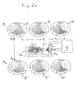
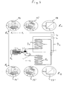
- FIG. 2 a, b and c Shown there is a device consisting of an electric motor 1a and a pump 2a, which feeds a consumer 7.
- the electrical power absorbed by the motor 1a is indicated by P 1 .
- the motor converts the electric power into a torque T e at a rotational speed ⁇ r .
- This am Output of the motor 1a pending mechanical power P 2 also represents the pending at the entrance of the pump 2a mechanical power P 2 , which is converted within the pump into a hydraulic power P 3 , by the pressure difference generated by the pump between the suction and discharge side ⁇ p and the flow rate through the pump q is determined.
- R s stator resistance
- L I s inductive losses of the stator
- L m magnetic induction
- L Ir inductive losses of the rotor
- R r rotor resistance
- J matrix ⁇ 0 - 1 1 0 are the constants of the engine.
- the constants are ⁇ p2 , ⁇ p1 , ⁇ p0 and p offset .
- Fig. 2a illustrated three-dimensional areas, which describe the power at the interfaces before, between and behind the functional units 1a and 2a, respectively, are detected and stored at a time t 1 .
- the detection typically occurs during normal operation for a short period of time which is negligibly small with respect to the monitoring interval (time from T 1 to t 2 ), after which, after a longer period of time, namely at time t 2, this process is repeated so that the surfaces according to the representations 8 ', 9' and 10 'result.
- Fig. 2a In monitoring as they are based on Fig. 2a is shown, there is a performance monitoring in front of and behind each functional unit 1a, 2a. However, this can be dispensable depending on the application. Also, it is not absolutely necessary to determine the surface curves having the multi-dimensional and model character representing the input or output power, as defined by equations 8, 9 and 10, but rather, like the embodiment according to FIG Fig. 2b clarified, for example, in place of the power P 3 as shown in Figure 10 in Fig. 2a Alternatively, the hydraulic power characteristic can be determined, that is, the differential pressure applied by the pump 2a as a function of the drive speed ⁇ r and the flow rate q. Which is detected and stored at time t 1 .
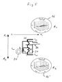
- Fig. 2c is another way of monitoring such a pump unit consisting of the functional units 1a and 2a shown.
- the power P 1 is detected there as a function of ⁇ e and Q as shown in FIG. 8 a and is compared with the corresponding power as shown in FIG. 8 a 'at a time interval between t 1 and t 2 .
- the power P 2 is determined there as a function of ⁇ p and ⁇ r , as the illustration according to 9a or 9a 'illustrates.
- the efficiency of the motor ⁇ m is the quotient of P 2 and P 1 and is dependent on ⁇ e (the supply frequency) and s , the slip of the motor.
- the motor efficiency is in Fig. 2c in the representation 11 a represented by the area in the diagram in each operating point.
- the illustration 9a shows the power P 2 in response to ⁇ p and q is shown.
- the power P 1 of the motor 1a is also represented in the form of a surface as a function of the supply frequency and the flow rate of the pump. Analogous to Fig.
- k ⁇ V n / ( n -1) / (2 ⁇ )
- n is a non-1 constant that describes heat flow during compression. If the process runs under constant temperature, then n can also be assumed to be constant.
- the engine power P 1 can be monitored in an analogous manner as indicated above by equation (8).
- Fig. 4 is the inventive method for a refrigerator shown consisting of a motor 1 c, a positive displacement pump 2 c, the output of which acts on an evaporator 3 c, which is connected via a throttle 4 c with a capacitor 5 c, the output of which is line connected to the input of the pump 2 c.
- the refrigerator is marked 7c.
- Equation 15 describes the power P 2 at the input of the compressor whereas equation 17 describes the power at the output of the compressor.
- the areas to be determined here for determining the power at the interfaces of the functional units may be two-dimensional or multi-dimensional.
- the area according to illustration 17 is two-dimensional, ie a line.
- the other surfaces shown here are all three-dimensional. It is understood that these surfaces may possibly be more than three-dimensional, depending on the type of machine to be monitored and the underlying mathematical physical relationships.
- the monitoring is carried out in an analogous manner by determining the power at the interfaces of the functional units surfaces according to representations 14, 15 and 17 at time t 1 and after a time interval at time t 2 (then resulting in the surfaces according to the Representations 14 '15' and 17 '), to then determine by determining the distance of the surfaces or the volume spanned therebetween, which of the functional units 1 c, 2 c, by which degree have fallen in their efficiency.
- ⁇ w is the density of the water and C pw is the specific heat capacity of the water.
- the inventive method can be used in a variety of devices such as aggregates, machines and equipment, which advantageously always the multi-dimensional surfaces are determined, each defining the power at the interfaces of the functional units to each other in any operating point and thus a reliable Measure for the performance characteristics of the functional units and with appropriate evaluation of the entire device, if they are compared at different times (eg, t 1 and t 2 ).
- times t 1 and t 2 are here to be understood as examples only, expediently the values determined at time t 1 always remain stored in order to be able to compare them with later ones, which however does not rule out that intermediate values are also stored if necessary, also to record the speed of the change. This too can be evaluated in a corresponding evaluation device.
- EP 1 564 411 A1 where comparable evaluations are described in detail.
- two-dimensional or more-dimensional surfaces have always been used to determine the power balance at the interfaces of the functional units, since this allows an evaluation virtually independent of the respective operating point. At substantially constant operating points, these evaluations can also take place in a simplified manner by comparing individual variables with one another over the time interval, indirectly or directly Conclusions about the efficiency can be made.
- the two- or multi-dimensional surfaces in question are advantageously determined during operation, whereby it is attempted by suitable iteration methods to achieve a high accuracy of the surfaces on the basis of as few as possible different operating points. This can be achieved in particular by using the Kálmánfilters, as has already been described above. However, other suitable iteration methods may be used. It is also conceivable that, for example, in a pump unit, certain operating points are approached targeted to capture the power balance representing surface area with the highest possible accuracy or to dispense with targeted detection of defined operating points on the determination of such areas.
Landscapes
- Engineering & Computer Science (AREA)
- Mechanical Engineering (AREA)
- General Engineering & Computer Science (AREA)
- Control Of Positive-Displacement Pumps (AREA)
- Control Of Non-Positive-Displacement Pumps (AREA)
- Domestic Hot-Water Supply Systems And Details Of Heating Systems (AREA)
Priority Applications (5)
| Application Number | Priority Date | Filing Date | Title |
|---|---|---|---|
| EP07018530.1A EP2039939B2 (fr) | 2007-09-20 | 2007-09-20 | Procédé de surveillance d'un dispositif de transformation d'énergie |
| CN200880108089.6A CN101802413B (zh) | 2007-09-20 | 2008-08-28 | 用于监测能量转换装置的方法 |
| JP2010525224A JP5439378B2 (ja) | 2007-09-20 | 2008-08-28 | エネルギー変換装置を監視する方法 |
| US12/679,054 US20100300220A1 (en) | 2007-09-20 | 2008-08-28 | Method for monitoring an energy conversion device |
| PCT/EP2008/007041 WO2009039934A1 (fr) | 2007-09-20 | 2008-08-28 | Procédé de surveillance d'un système de conversion d'énergie |
Applications Claiming Priority (1)
| Application Number | Priority Date | Filing Date | Title |
|---|---|---|---|
| EP07018530.1A EP2039939B2 (fr) | 2007-09-20 | 2007-09-20 | Procédé de surveillance d'un dispositif de transformation d'énergie |
Publications (3)
| Publication Number | Publication Date |
|---|---|
| EP2039939A1 true EP2039939A1 (fr) | 2009-03-25 |
| EP2039939B1 EP2039939B1 (fr) | 2017-08-09 |
| EP2039939B2 EP2039939B2 (fr) | 2020-11-18 |
Family
ID=39144574
Family Applications (1)
| Application Number | Title | Priority Date | Filing Date |
|---|---|---|---|
| EP07018530.1A Not-in-force EP2039939B2 (fr) | 2007-09-20 | 2007-09-20 | Procédé de surveillance d'un dispositif de transformation d'énergie |
Country Status (5)
| Country | Link |
|---|---|
| US (1) | US20100300220A1 (fr) |
| EP (1) | EP2039939B2 (fr) |
| JP (1) | JP5439378B2 (fr) |
| CN (1) | CN101802413B (fr) |
| WO (1) | WO2009039934A1 (fr) |
Cited By (1)
| Publication number | Priority date | Publication date | Assignee | Title |
|---|---|---|---|---|
| DE102023111782A1 (de) | 2023-05-05 | 2024-11-07 | KSB SE & Co. KGaA | Verfahren zur Detektion von Kavitation und/oder einer Lufteinperlung bzw. Lufteinströmung innerhalb eines hydraulischen Systems |
Families Citing this family (14)
| Publication number | Priority date | Publication date | Assignee | Title |
|---|---|---|---|---|
| JP5437687B2 (ja) * | 2009-04-14 | 2014-03-12 | ナブテスコ株式会社 | アクチュエータ監視回路、制御装置、およびアクチュエータユニット |
| WO2010144782A1 (fr) * | 2009-06-12 | 2010-12-16 | Cidra Corporate Services Inc. | Procédé et appareil pour prédire des besoins de maintenance d'une pompe sur la base au moins en partie d'une analyse de performance de pompe |
| US20130204546A1 (en) * | 2012-02-02 | 2013-08-08 | Ghd Pty Ltd. | On-line pump efficiency determining system and related method for determining pump efficiency |
| JP2014202144A (ja) * | 2013-04-05 | 2014-10-27 | 新日本造機株式会社 | 遠心ポンプの診断方法 |
| JP6776078B2 (ja) * | 2016-09-26 | 2020-10-28 | 朝日ライフサイエンス株式会社 | フリーザ監視装置、フリーザ監視システム及びフリーザ監視方法 |
| EP4365453A3 (fr) * | 2016-12-30 | 2024-07-10 | Grundfos Holding A/S | Procédé de fonctionnement d'un groupe motopompe à commande électronique |
| DE102018200651A1 (de) * | 2018-01-16 | 2019-07-18 | KSB SE & Co. KGaA | Verfahren zur Eigendiagnose des mechanischen und/oder hydraulischen Zustandes einer Kreiselpumpe |
| EP3567256B1 (fr) * | 2018-05-11 | 2025-07-02 | Grundfos Holding A/S | Module de surveillance et procédé permettant d'identifier un scénario de fonctionnement dans une station de pompage des eaux usées |
| FR3094421A1 (fr) * | 2019-03-29 | 2020-10-02 | Wilo Intec | Procede de maintenance predictive d’une pompe de circulation d’un fluide |
| EP4019779A1 (fr) | 2020-12-23 | 2022-06-29 | Grundfos Holding A/S | Système et procédé de surveillance de pompe pour associer un état de fonctionnement actuel d'un système de pompe à un ou plusieurs scénarios de panne |
| CN114235271B (zh) * | 2021-11-12 | 2024-01-12 | 潍柴动力股份有限公司 | 压差传感器的露点检测方法、装置、存储介质和设备 |
| US20250042570A1 (en) * | 2023-07-31 | 2025-02-06 | United Airlines, Inc. | Cabin air compressor failure alert system |
| EP4711241A1 (fr) | 2024-09-12 | 2026-03-18 | KB Intellectual Property GmbH & Co. KG | Procédé et système de détection de dégradation d'un système de direction assistée |
| JP7814646B1 (ja) * | 2025-06-27 | 2026-02-16 | 三菱電機株式会社 | 電動機負荷設備の診断装置 |
Citations (4)
| Publication number | Priority date | Publication date | Assignee | Title |
|---|---|---|---|---|
| DE19618462A1 (de) * | 1996-05-08 | 1997-11-13 | Status Pro Maschinenmesstechni | Verfahren und Vorrichtung zum Bestimmen eines extrinsischen Leistungsparameters einer energieumwandelnden Vorrichtung |
| EP1564411A1 (fr) | 2004-02-11 | 2005-08-17 | Grundfos A/S | Procédé de detection des erreurs de fonctionnement d'une unité de pompage |
| US20050251362A1 (en) * | 2004-06-05 | 2005-11-10 | Ollre Albert G | System and method for determining pump underperformance |
| DE102007009301A1 (de) | 2006-03-08 | 2007-09-13 | ITT Manufacturing Enterprises, Inc., Wilmington | Verfahren und Vorrichtung zum Pumpenschutz ohne den Einsatz traditioneller Sensoren |
Family Cites Families (24)
| Publication number | Priority date | Publication date | Assignee | Title |
|---|---|---|---|---|
| US4584654A (en) † | 1982-10-21 | 1986-04-22 | Ultra Products Systems, Inc. | Method and system for monitoring operating efficiency of pipeline system |
| DE3402120A1 (de) | 1984-01-23 | 1985-07-25 | Rheinhütte vorm. Ludwig Beck GmbH & Co, 6200 Wiesbaden | Verfahren und vorrichtung zur regelung verschiedener betriebsparameter bei pumpen und verdichtern |
| JPS6163491U (fr) | 1984-10-02 | 1986-04-30 | ||
| JPH07117046B2 (ja) * | 1988-12-27 | 1995-12-18 | 株式会社東芝 | ポンプ制御装置 |
| US5742500A (en) | 1995-08-23 | 1998-04-21 | Irvin; William A. | Pump station control system and method |
| US6260004B1 (en) † | 1997-12-31 | 2001-07-10 | Innovation Management Group, Inc. | Method and apparatus for diagnosing a pump system |
| AU3053799A (en) | 1998-04-03 | 1999-10-25 | Ebara Corporation | Diagnosing system for fluid machinery |
| US20010010032A1 (en) * | 1998-10-27 | 2001-07-26 | Ehlers Gregory A. | Energy management and building automation system |
| US6584784B2 (en) * | 1999-02-05 | 2003-07-01 | Midwest Research Institute | Combined refrigeration system with a liquid pre-cooling heat exchanger |
| US6185944B1 (en) * | 1999-02-05 | 2001-02-13 | Midwest Research Institute | Refrigeration system with a compressor-pump unit and a liquid-injection desuperheating line |
| US6464464B2 (en) † | 1999-03-24 | 2002-10-15 | Itt Manufacturing Enterprises, Inc. | Apparatus and method for controlling a pump system |
| JP2003028076A (ja) * | 2001-07-12 | 2003-01-29 | Hitachi Ltd | ポンプ異常診断装置 |
| US6648606B2 (en) † | 2002-01-17 | 2003-11-18 | Itt Manufacturing Enterprises, Inc. | Centrifugal pump performance degradation detection |
| US7368853B2 (en) * | 2002-04-22 | 2008-05-06 | Elliptec Resonant Actuator Aktiengesellschaft | Piezoelectric motors and methods for the production and operation thereof |
| US6709240B1 (en) * | 2002-11-13 | 2004-03-23 | Eaton Corporation | Method and apparatus of detecting low flow/cavitation in a centrifugal pump |
| WO2005057086A1 (fr) * | 2003-12-12 | 2005-06-23 | Rinnai Corporation | Systeme d'alimentation en eau chaude |
| DE10359726A1 (de) | 2003-12-19 | 2005-07-14 | Ksb Aktiengesellschaft | Mengenmessung |
| JP4265982B2 (ja) * | 2004-02-25 | 2009-05-20 | 三菱電機株式会社 | 機器診断装置、冷凍サイクル装置、冷凍サイクル監視システム |
| JP4625306B2 (ja) * | 2004-10-28 | 2011-02-02 | 三菱重工業株式会社 | 流体機械の性能診断装置及びシステム |
| JP2006226574A (ja) * | 2005-02-16 | 2006-08-31 | Paloma Ind Ltd | 温水循環加熱装置 |
| NZ538737A (en) * | 2005-03-10 | 2008-04-30 | Hot Water Innovations Ltd | Electronic control of water storage (hot water storage) parameters and operation |
| CN1693711A (zh) * | 2005-06-03 | 2005-11-09 | 王黎明 | 智能水泵电机控制装置 |
| CN1302269C (zh) * | 2005-12-16 | 2007-02-28 | 陈育青 | 一种能够实时监测转辙机转换阻力的方法及其监测设备 |
| DE102007022348A1 (de) | 2007-05-12 | 2008-11-13 | Ksb Aktiengesellschaft | Einrichtung und Verfahren zur Störungsüberwachung |
-
2007
- 2007-09-20 EP EP07018530.1A patent/EP2039939B2/fr not_active Not-in-force
-
2008
- 2008-08-28 CN CN200880108089.6A patent/CN101802413B/zh not_active Expired - Fee Related
- 2008-08-28 US US12/679,054 patent/US20100300220A1/en not_active Abandoned
- 2008-08-28 JP JP2010525224A patent/JP5439378B2/ja not_active Expired - Fee Related
- 2008-08-28 WO PCT/EP2008/007041 patent/WO2009039934A1/fr not_active Ceased
Patent Citations (4)
| Publication number | Priority date | Publication date | Assignee | Title |
|---|---|---|---|---|
| DE19618462A1 (de) * | 1996-05-08 | 1997-11-13 | Status Pro Maschinenmesstechni | Verfahren und Vorrichtung zum Bestimmen eines extrinsischen Leistungsparameters einer energieumwandelnden Vorrichtung |
| EP1564411A1 (fr) | 2004-02-11 | 2005-08-17 | Grundfos A/S | Procédé de detection des erreurs de fonctionnement d'une unité de pompage |
| US20050251362A1 (en) * | 2004-06-05 | 2005-11-10 | Ollre Albert G | System and method for determining pump underperformance |
| DE102007009301A1 (de) | 2006-03-08 | 2007-09-13 | ITT Manufacturing Enterprises, Inc., Wilmington | Verfahren und Vorrichtung zum Pumpenschutz ohne den Einsatz traditioneller Sensoren |
Cited By (1)
| Publication number | Priority date | Publication date | Assignee | Title |
|---|---|---|---|---|
| DE102023111782A1 (de) | 2023-05-05 | 2024-11-07 | KSB SE & Co. KGaA | Verfahren zur Detektion von Kavitation und/oder einer Lufteinperlung bzw. Lufteinströmung innerhalb eines hydraulischen Systems |
Also Published As
| Publication number | Publication date |
|---|---|
| WO2009039934A1 (fr) | 2009-04-02 |
| CN101802413B (zh) | 2014-07-30 |
| JP2010539380A (ja) | 2010-12-16 |
| JP5439378B2 (ja) | 2014-03-12 |
| EP2039939B2 (fr) | 2020-11-18 |
| US20100300220A1 (en) | 2010-12-02 |
| CN101802413A (zh) | 2010-08-11 |
| EP2039939B1 (fr) | 2017-08-09 |
Similar Documents
| Publication | Publication Date | Title |
|---|---|---|
| EP2039939B1 (fr) | Procédé de surveillance d'un dispositif de transformation d'énergie | |
| EP4224016B1 (fr) | Dispositif de commande électronique pour un composant de génération d'air comprimé, de traitement d'air comprimé, d'accumulation d'air comprimé et/ou de distribution d'air comprimé | |
| EP2258949B1 (fr) | Procédé de détermination de valeurs caractéristiques, notamment de valeurs, notamment de paramètres, d'un agrégat de pompe centrifuge entraîné par moteur électrique intégré dans une installation | |
| DE10355651B4 (de) | Verfahren zur Optimierung des Wirkungsgrades eines unter Last betriebenen Motors | |
| EP3449132B1 (fr) | Procédé de détection d'un état de fonctionnement anormal d'un groupe de pompage | |
| EP1564411B1 (fr) | Procédé de détection des erreurs de fonctionnement d'une unité de pompage | |
| EP1286240B1 (fr) | Méthode de détermination d'une caractéristique de pompe | |
| EP3242035B1 (fr) | Procédé de fonctionnement d'au moins un groupe motopompe parmi une pluralité de groupes motopompe | |
| EP2927662B1 (fr) | Procédé et système de surveillance de l'état d'un palier de roulement d'une éolienne | |
| EP3739212A1 (fr) | Procédé de détermination d'un volume d'écoulement d'un fluide transporté par une pompe | |
| DE102014008716B4 (de) | Verfahren zur Erkennung eines Trockenlaufs | |
| EP3841366B1 (fr) | Procédé et système pour la détermination directe d'un endommagement théorique d'au moins un organe d'un dispositif | |
| EP1801415A2 (fr) | Éolienne avec un dispositif de graissage pour le palier du générateur | |
| WO2020025754A1 (fr) | Pompe à vide | |
| WO2009062325A1 (fr) | Machine destinée à ouvrir des balles | |
| EP3298306B1 (fr) | Procédé permettant de faire fonctionner une pompe d'alimentation à commande électrique dans un circuit hydraulique | |
| EP1653050A1 (fr) | Procédé pour déterminer une valeur caractéristique réfléchissant l'état de fatigue d'un composant | |
| CH680688A5 (fr) | ||
| DE102008036305B4 (de) | Verfahren zum Betreiben eines Verdichters | |
| DE102021006682A1 (de) | Verfahren sowie Vorrichtung zur Überwachung einer Kältemittel-Anlage | |
| DE102009056575B4 (de) | Verfahren und Vorrichtung zum Ermitteln eines modellierten Temperaturwertes bei einer Brennkraftmaschine und Verfahren zur Plausibilisierung eines Temperatursensors | |
| EP1203886B1 (fr) | Méthode déterminant au moins une caractéristique d'un liquide pompé | |
| EP1873898A2 (fr) | Procédé destiné à la régulation d'une pompe destinée à l'approvisionnement d'un milieu liquide | |
| DE102015206589A1 (de) | Verfahren zum Bestimmen einer Temperatur einer Membran einer Pumpe | |
| EP4261413B1 (fr) | Dispositif et procédé de détermination d'un état, en particulier d'un état d'usure, d'une unité de déplacement |
Legal Events
| Date | Code | Title | Description |
|---|---|---|---|
| PUAI | Public reference made under article 153(3) epc to a published international application that has entered the european phase |
Free format text: ORIGINAL CODE: 0009012 |
|
| AK | Designated contracting states |
Kind code of ref document: A1 Designated state(s): AT BE BG CH CY CZ DE DK EE ES FI FR GB GR HU IE IS IT LI LT LU LV MC MT NL PL PT RO SE SI SK TR |
|
| AX | Request for extension of the european patent |
Extension state: AL BA HR MK RS |
|
| 17P | Request for examination filed |
Effective date: 20090729 |
|
| 17Q | First examination report despatched |
Effective date: 20090826 |
|
| AKX | Designation fees paid |
Designated state(s): AT BE BG CH CY CZ DE DK EE ES FI FR GB GR HU IE IS IT LI LT LU LV MC MT NL PL PT RO SE SI SK TR |
|
| GRAP | Despatch of communication of intention to grant a patent |
Free format text: ORIGINAL CODE: EPIDOSNIGR1 |
|
| STAA | Information on the status of an ep patent application or granted ep patent |
Free format text: STATUS: GRANT OF PATENT IS INTENDED |
|
| INTG | Intention to grant announced |
Effective date: 20170123 |
|
| GRAS | Grant fee paid |
Free format text: ORIGINAL CODE: EPIDOSNIGR3 |
|
| GRAJ | Information related to disapproval of communication of intention to grant by the applicant or resumption of examination proceedings by the epo deleted |
Free format text: ORIGINAL CODE: EPIDOSDIGR1 |
|
| GRAL | Information related to payment of fee for publishing/printing deleted |
Free format text: ORIGINAL CODE: EPIDOSDIGR3 |
|
| STAA | Information on the status of an ep patent application or granted ep patent |
Free format text: STATUS: EXAMINATION IS IN PROGRESS |
|
| GRAR | Information related to intention to grant a patent recorded |
Free format text: ORIGINAL CODE: EPIDOSNIGR71 |
|
| STAA | Information on the status of an ep patent application or granted ep patent |
Free format text: STATUS: GRANT OF PATENT IS INTENDED |
|
| INTC | Intention to grant announced (deleted) | ||
| GRAA | (expected) grant |
Free format text: ORIGINAL CODE: 0009210 |
|
| STAA | Information on the status of an ep patent application or granted ep patent |
Free format text: STATUS: THE PATENT HAS BEEN GRANTED |
|
| INTG | Intention to grant announced |
Effective date: 20170629 |
|
| AK | Designated contracting states |
Kind code of ref document: B1 Designated state(s): AT BE BG CH CY CZ DE DK EE ES FI FR GB GR HU IE IS IT LI LT LU LV MC MT NL PL PT RO SE SI SK TR |
|
| REG | Reference to a national code |
Ref country code: GB Ref legal event code: FG4D Free format text: NOT ENGLISH |
|
| REG | Reference to a national code |
Ref country code: CH Ref legal event code: EP Ref country code: AT Ref legal event code: REF Ref document number: 917177 Country of ref document: AT Kind code of ref document: T Effective date: 20170815 |
|
| REG | Reference to a national code |
Ref country code: IE Ref legal event code: FG4D Free format text: LANGUAGE OF EP DOCUMENT: GERMAN |
|
| REG | Reference to a national code |
Ref country code: DE Ref legal event code: R096 Ref document number: 502007015791 Country of ref document: DE |
|
| REG | Reference to a national code |
Ref country code: FR Ref legal event code: PLFP Year of fee payment: 11 |
|
| REG | Reference to a national code |
Ref country code: NL Ref legal event code: MP Effective date: 20170809 |
|
| REG | Reference to a national code |
Ref country code: LT Ref legal event code: MG4D |
|
| PG25 | Lapsed in a contracting state [announced via postgrant information from national office to epo] |
Ref country code: FI Free format text: LAPSE BECAUSE OF FAILURE TO SUBMIT A TRANSLATION OF THE DESCRIPTION OR TO PAY THE FEE WITHIN THE PRESCRIBED TIME-LIMIT Effective date: 20170809 Ref country code: SE Free format text: LAPSE BECAUSE OF FAILURE TO SUBMIT A TRANSLATION OF THE DESCRIPTION OR TO PAY THE FEE WITHIN THE PRESCRIBED TIME-LIMIT Effective date: 20170809 Ref country code: LT Free format text: LAPSE BECAUSE OF FAILURE TO SUBMIT A TRANSLATION OF THE DESCRIPTION OR TO PAY THE FEE WITHIN THE PRESCRIBED TIME-LIMIT Effective date: 20170809 Ref country code: NL Free format text: LAPSE BECAUSE OF FAILURE TO SUBMIT A TRANSLATION OF THE DESCRIPTION OR TO PAY THE FEE WITHIN THE PRESCRIBED TIME-LIMIT Effective date: 20170809 |
|
| PG25 | Lapsed in a contracting state [announced via postgrant information from national office to epo] |
Ref country code: ES Free format text: LAPSE BECAUSE OF FAILURE TO SUBMIT A TRANSLATION OF THE DESCRIPTION OR TO PAY THE FEE WITHIN THE PRESCRIBED TIME-LIMIT Effective date: 20170809 Ref country code: LV Free format text: LAPSE BECAUSE OF FAILURE TO SUBMIT A TRANSLATION OF THE DESCRIPTION OR TO PAY THE FEE WITHIN THE PRESCRIBED TIME-LIMIT Effective date: 20170809 Ref country code: GR Free format text: LAPSE BECAUSE OF FAILURE TO SUBMIT A TRANSLATION OF THE DESCRIPTION OR TO PAY THE FEE WITHIN THE PRESCRIBED TIME-LIMIT Effective date: 20171110 Ref country code: IS Free format text: LAPSE BECAUSE OF FAILURE TO SUBMIT A TRANSLATION OF THE DESCRIPTION OR TO PAY THE FEE WITHIN THE PRESCRIBED TIME-LIMIT Effective date: 20171209 Ref country code: PL Free format text: LAPSE BECAUSE OF FAILURE TO SUBMIT A TRANSLATION OF THE DESCRIPTION OR TO PAY THE FEE WITHIN THE PRESCRIBED TIME-LIMIT Effective date: 20170809 Ref country code: BG Free format text: LAPSE BECAUSE OF FAILURE TO SUBMIT A TRANSLATION OF THE DESCRIPTION OR TO PAY THE FEE WITHIN THE PRESCRIBED TIME-LIMIT Effective date: 20171109 |
|
| PG25 | Lapsed in a contracting state [announced via postgrant information from national office to epo] |
Ref country code: RO Free format text: LAPSE BECAUSE OF FAILURE TO SUBMIT A TRANSLATION OF THE DESCRIPTION OR TO PAY THE FEE WITHIN THE PRESCRIBED TIME-LIMIT Effective date: 20170809 Ref country code: CZ Free format text: LAPSE BECAUSE OF FAILURE TO SUBMIT A TRANSLATION OF THE DESCRIPTION OR TO PAY THE FEE WITHIN THE PRESCRIBED TIME-LIMIT Effective date: 20170809 Ref country code: DK Free format text: LAPSE BECAUSE OF FAILURE TO SUBMIT A TRANSLATION OF THE DESCRIPTION OR TO PAY THE FEE WITHIN THE PRESCRIBED TIME-LIMIT Effective date: 20170809 |
|
| REG | Reference to a national code |
Ref country code: CH Ref legal event code: PL |
|
| REG | Reference to a national code |
Ref country code: DE Ref legal event code: R026 Ref document number: 502007015791 Country of ref document: DE |
|
| PLBI | Opposition filed |
Free format text: ORIGINAL CODE: 0009260 |
|
| PLAX | Notice of opposition and request to file observation + time limit sent |
Free format text: ORIGINAL CODE: EPIDOSNOBS2 |
|
| PG25 | Lapsed in a contracting state [announced via postgrant information from national office to epo] |
Ref country code: EE Free format text: LAPSE BECAUSE OF FAILURE TO SUBMIT A TRANSLATION OF THE DESCRIPTION OR TO PAY THE FEE WITHIN THE PRESCRIBED TIME-LIMIT Effective date: 20170809 Ref country code: SK Free format text: LAPSE BECAUSE OF FAILURE TO SUBMIT A TRANSLATION OF THE DESCRIPTION OR TO PAY THE FEE WITHIN THE PRESCRIBED TIME-LIMIT Effective date: 20170809 Ref country code: MC Free format text: LAPSE BECAUSE OF FAILURE TO SUBMIT A TRANSLATION OF THE DESCRIPTION OR TO PAY THE FEE WITHIN THE PRESCRIBED TIME-LIMIT Effective date: 20170809 |
|
| 26 | Opposition filed |
Opponent name: KSB AKTIENGESELLSCHAFT Effective date: 20180508 |
|
| REG | Reference to a national code |
Ref country code: IE Ref legal event code: MM4A |
|
| REG | Reference to a national code |
Ref country code: BE Ref legal event code: MM Effective date: 20170930 |
|
| PG25 | Lapsed in a contracting state [announced via postgrant information from national office to epo] |
Ref country code: LU Free format text: LAPSE BECAUSE OF NON-PAYMENT OF DUE FEES Effective date: 20170920 |
|
| PG25 | Lapsed in a contracting state [announced via postgrant information from national office to epo] |
Ref country code: IE Free format text: LAPSE BECAUSE OF NON-PAYMENT OF DUE FEES Effective date: 20170920 Ref country code: LI Free format text: LAPSE BECAUSE OF NON-PAYMENT OF DUE FEES Effective date: 20170930 Ref country code: CH Free format text: LAPSE BECAUSE OF NON-PAYMENT OF DUE FEES Effective date: 20170930 |
|
| PG25 | Lapsed in a contracting state [announced via postgrant information from national office to epo] |
Ref country code: SI Free format text: LAPSE BECAUSE OF FAILURE TO SUBMIT A TRANSLATION OF THE DESCRIPTION OR TO PAY THE FEE WITHIN THE PRESCRIBED TIME-LIMIT Effective date: 20170809 Ref country code: BE Free format text: LAPSE BECAUSE OF NON-PAYMENT OF DUE FEES Effective date: 20170930 |
|
| REG | Reference to a national code |
Ref country code: FR Ref legal event code: PLFP Year of fee payment: 12 |
|
| PG25 | Lapsed in a contracting state [announced via postgrant information from national office to epo] |
Ref country code: MT Free format text: LAPSE BECAUSE OF FAILURE TO SUBMIT A TRANSLATION OF THE DESCRIPTION OR TO PAY THE FEE WITHIN THE PRESCRIBED TIME-LIMIT Effective date: 20170809 |
|
| PLBB | Reply of patent proprietor to notice(s) of opposition received |
Free format text: ORIGINAL CODE: EPIDOSNOBS3 |
|
| REG | Reference to a national code |
Ref country code: AT Ref legal event code: MM01 Ref document number: 917177 Country of ref document: AT Kind code of ref document: T Effective date: 20170920 |
|
| PG25 | Lapsed in a contracting state [announced via postgrant information from national office to epo] |
Ref country code: AT Free format text: LAPSE BECAUSE OF NON-PAYMENT OF DUE FEES Effective date: 20170920 |
|
| PG25 | Lapsed in a contracting state [announced via postgrant information from national office to epo] |
Ref country code: HU Free format text: LAPSE BECAUSE OF FAILURE TO SUBMIT A TRANSLATION OF THE DESCRIPTION OR TO PAY THE FEE WITHIN THE PRESCRIBED TIME-LIMIT; INVALID AB INITIO Effective date: 20070920 |
|
| PG25 | Lapsed in a contracting state [announced via postgrant information from national office to epo] |
Ref country code: CY Free format text: LAPSE BECAUSE OF NON-PAYMENT OF DUE FEES Effective date: 20170809 |
|
| APAH | Appeal reference modified |
Free format text: ORIGINAL CODE: EPIDOSCREFNO |
|
| APBM | Appeal reference recorded |
Free format text: ORIGINAL CODE: EPIDOSNREFNO |
|
| APBP | Date of receipt of notice of appeal recorded |
Free format text: ORIGINAL CODE: EPIDOSNNOA2O |
|
| PLAB | Opposition data, opponent's data or that of the opponent's representative modified |
Free format text: ORIGINAL CODE: 0009299OPPO |
|
| PG25 | Lapsed in a contracting state [announced via postgrant information from national office to epo] |
Ref country code: TR Free format text: LAPSE BECAUSE OF FAILURE TO SUBMIT A TRANSLATION OF THE DESCRIPTION OR TO PAY THE FEE WITHIN THE PRESCRIBED TIME-LIMIT Effective date: 20170809 |
|
| APBM | Appeal reference recorded |
Free format text: ORIGINAL CODE: EPIDOSNREFNO |
|
| APBP | Date of receipt of notice of appeal recorded |
Free format text: ORIGINAL CODE: EPIDOSNNOA2O |
|
| R26 | Opposition filed (corrected) |
Opponent name: KSB SE & CO. KGAA Effective date: 20180508 |
|
| PG25 | Lapsed in a contracting state [announced via postgrant information from national office to epo] |
Ref country code: PT Free format text: LAPSE BECAUSE OF FAILURE TO SUBMIT A TRANSLATION OF THE DESCRIPTION OR TO PAY THE FEE WITHIN THE PRESCRIBED TIME-LIMIT Effective date: 20170809 |
|
| APBU | Appeal procedure closed |
Free format text: ORIGINAL CODE: EPIDOSNNOA9O |
|
| PUAH | Patent maintained in amended form |
Free format text: ORIGINAL CODE: 0009272 |
|
| STAA | Information on the status of an ep patent application or granted ep patent |
Free format text: STATUS: PATENT MAINTAINED AS AMENDED |
|
| 27A | Patent maintained in amended form |
Effective date: 20201118 |
|
| AK | Designated contracting states |
Kind code of ref document: B2 Designated state(s): AT BE BG CH CY CZ DE DK EE ES FI FR GB GR HU IE IS IT LI LT LU LV MC MT NL PL PT RO SE SI SK TR |
|
| REG | Reference to a national code |
Ref country code: DE Ref legal event code: R102 Ref document number: 502007015791 Country of ref document: DE |
|
| REG | Reference to a national code |
Ref country code: DE Ref legal event code: R082 Ref document number: 502007015791 Country of ref document: DE |
|
| PGFP | Annual fee paid to national office [announced via postgrant information from national office to epo] |
Ref country code: GB Payment date: 20230920 Year of fee payment: 17 |
|
| PGFP | Annual fee paid to national office [announced via postgrant information from national office to epo] |
Ref country code: FR Payment date: 20230928 Year of fee payment: 17 Ref country code: DE Payment date: 20230920 Year of fee payment: 17 |
|
| PGFP | Annual fee paid to national office [announced via postgrant information from national office to epo] |
Ref country code: IT Payment date: 20230927 Year of fee payment: 17 |
|
| REG | Reference to a national code |
Ref country code: DE Ref legal event code: R119 Ref document number: 502007015791 Country of ref document: DE |
|
| GBPC | Gb: european patent ceased through non-payment of renewal fee |
Effective date: 20240920 |
|
| PG25 | Lapsed in a contracting state [announced via postgrant information from national office to epo] |
Ref country code: DE Free format text: LAPSE BECAUSE OF NON-PAYMENT OF DUE FEES Effective date: 20250401 |
|
| PG25 | Lapsed in a contracting state [announced via postgrant information from national office to epo] |
Ref country code: GB Free format text: LAPSE BECAUSE OF NON-PAYMENT OF DUE FEES Effective date: 20240920 |
|
| PG25 | Lapsed in a contracting state [announced via postgrant information from national office to epo] |
Ref country code: IT Free format text: LAPSE BECAUSE OF NON-PAYMENT OF DUE FEES Effective date: 20240920 |
|
| PG25 | Lapsed in a contracting state [announced via postgrant information from national office to epo] |
Ref country code: FR Free format text: LAPSE BECAUSE OF NON-PAYMENT OF DUE FEES Effective date: 20240930 |