EP2040027A2 - Appareil pour mesurer l'épaisseur de paroi d'objets - Google Patents
Appareil pour mesurer l'épaisseur de paroi d'objets Download PDFInfo
- Publication number
- EP2040027A2 EP2040027A2 EP08022396A EP08022396A EP2040027A2 EP 2040027 A2 EP2040027 A2 EP 2040027A2 EP 08022396 A EP08022396 A EP 08022396A EP 08022396 A EP08022396 A EP 08022396A EP 2040027 A2 EP2040027 A2 EP 2040027A2
- Authority
- EP
- European Patent Office
- Prior art keywords
- probe
- ultrasonic test
- coordinate measuring
- measuring machine
- contact
- Prior art date
- Legal status (The legal status is an assumption and is not a legal conclusion. Google has not performed a legal analysis and makes no representation as to the accuracy of the status listed.)
- Granted
Links
Images
Classifications
-
- G—PHYSICS
- G01—MEASURING; TESTING
- G01B—MEASURING LENGTH, THICKNESS OR SIMILAR LINEAR DIMENSIONS; MEASURING ANGLES; MEASURING AREAS; MEASURING IRREGULARITIES OF SURFACES OR CONTOURS
- G01B17/00—Measuring arrangements characterised by the use of infrasonic, sonic or ultrasonic vibrations
- G01B17/02—Measuring arrangements characterised by the use of infrasonic, sonic or ultrasonic vibrations for measuring thickness
-
- G—PHYSICS
- G01—MEASURING; TESTING
- G01B—MEASURING LENGTH, THICKNESS OR SIMILAR LINEAR DIMENSIONS; MEASURING ANGLES; MEASURING AREAS; MEASURING IRREGULARITIES OF SURFACES OR CONTOURS
- G01B21/00—Measuring arrangements or details thereof, where the measuring technique is not covered by the other groups of this subclass, unspecified or not relevant
- G01B21/02—Measuring arrangements or details thereof, where the measuring technique is not covered by the other groups of this subclass, unspecified or not relevant for measuring length, width, or thickness
- G01B21/04—Measuring arrangements or details thereof, where the measuring technique is not covered by the other groups of this subclass, unspecified or not relevant for measuring length, width, or thickness by measuring coordinates of points
Definitions
- the present invention relates to an apparatus for measuring wall thicknesses of objects, and particularly, but not exclusively, to an apparatus in which the measured wall thicknesses can be converted to spatial coordinates on surfaces of objects.
- Manufactured objects often have to conform to dimensional and/or geometrical tolerances. These may be specified by the manufacturer or ultimate user of the object e.g. to ensure that the object behaves correctly in service. Thus it is common to subject objects to post-manufacture inspection procedures.
- a known technique for determining the dimensional accuracy of objects involves driving a coordinate measuring probe or stylus over the surface of the object.
- a probe typically comprises a stiff elongate member (formed e.g. of carbon fibre) having a small hard (typically industrial ruby) sphere at the measuring end.
- An example of a commercially available probe is the Renishaw SP600 TM analogue scanning probe.
- the probe is fitted to a Renishaw MIH TM head providing angular movement about two orthogonal axes in 7.5 increments.
- the head is then mounted to the quill of a programmable coordinate measuring machine (CMM), which controls the movement of the probe.
- CCM programmable coordinate measuring machine
- a typical CMM comprises a quill providing z-direction movement, a carriage assembly which carries the quill and provides x- and y-direction movement, and a measuring table, as shown for example in US 5189805 .
- the CMM typically also comprises a programmable computer to control the probe movements.
- CMMs are commercially available from a number of suppliers.
- Sensing means associated with the probe detects when and where the sphere contacts a surface and the CMM translates that information into a spatial coordinate for the surface contact point with the sphere.
- the probe can provide discrete measurements of the relative positions of these points. In this way, shape characteristics (such as profiles or outlines) of the actual object can be built up, and these characteristics can then be compared for conformity with e.g. predetermined tolerance limits.
- the operator programs a guide path by a teach-and-learn technique in which he drives the probe under manual control to specific points along the desired guide path, and saves the positions of those points in the memory of the CMM.
- the CMM subsequently drives the probe from point-to-point in an order determined by the operator, taking measurements along the way.
- the operator will also specify approach directions and probe angles to ensure that the probe or quill does not collide with the object.
- the operator may also program the quill to change the probe (usually at a probe change station remote from the object) so that e.g. a probe with a longer elongate member is used to reach otherwise-inaccessible parts of the object.
- Gas turbine engine components and particularly critical components such as blades, vanes and discs, are commonly inspected using such techniques.
- gas turbine blades and vanes to be formed as hollow components, with internal cavities which reduce the weight of the component and/or provide cooling channels.
- a known technique for producing hollow titanium alloy fan blades involves superplastic forming of the blade to expand internal blade cavities, followed by acid dipping of the blade to taper etch the external surface and provide the desired aerofoil shape. The external surface may then be linished to give the desired surface finish.
- variability can be introduced into the thickness of the blade walls which define the cavities, i.e. there can be a degree of uncertainty in the positions of the internal surfaces of the cavities.
- an object of the present invention is to provide an apparatus which enables the measurement of wall thicknesses and preferably the spatial coordinates of positions on internal surfaces of an object.
- the present invention is at least partly based on the realisation that an ultrasonic test probe can be mounted to a CMM to provide wall thickness measurements at predetermined probe contact positions on an object. If the spatial coordinates of these contact positions are known, each wall thickness measurement can be converted into spatial coordinates for the opposing position on the other side of the wall to the probe contact position.
- the present invention provides an apparatus for measuring wall thicknesses of objects, the apparatus comprising:
- the apparatus further comprises:
- the present invention may also provide an apparatus for measuring wall thicknesses of objects, the apparatus comprising:
- the apparatus further comprises an angle adjustment mechanism that adjusts the angle of the ultrasonic test probe when it is brought into contact with said surface so that the measured wall thickness is along a line perpendicular to said surface.
- the angle adjustment mechanism may comprise gymbals.
- the gymbals can connect the probe to the probe holder. In this way, when the probe is offered to the object surface, the gymbals can correct any misalignment between the probe and the surface.
- the probe holder is adapted to provide angular movement of the probe about two or more axes so that the coordinate measuring machine can at least approximately align the probe before it is offered to the object surface.
- An object may be located at the object support, the object having walls which on one side are contactable by the ultrasonic test probe and on the other side are not contactable by the probe.
- the object may be a vane or blade of a gas turbine engine.
- the coordinate measuring machine further comprises a computer system which (i) controls the probe movements, (ii) commands thickness measurements by the probe, and/or (iii) stores thickness measurements made by the probe.
- the computer system can relate each measured wall thickness to one or more reference positions for the object and thereby converts the measured wall thickness into spatial coordinates for the opposing position on the other side of the wall to the probe contact position.
- the computer system may store the spatial coordinates of each probe contact position, whereby the reference position for each measured wall thickness is the corresponding probe contact position.
- the computer system defines the spatial coordinates relative to one or more axes and/or directions of the gas turbine engine.
- the fundamental axes of the coordinates system may include the gas turbine engine centre axis.
- the axes include the engine centre axis and a radial engine direction along the length of the vane or blade.
- the coordinate measuring machine is also used to measure the spatial coordinates of the probe contact positions.
- the apparatus may further comprise at least one coordinate measuring stylus which is interchangeable with the ultrasonic test probe, such that the coordinate measuring stylus can be held by the probe holder when the ultrasonic test probe is not in use. The coordinate measuring stylus is then movable by the coordinate measuring machine into contact with the object at the probe contact positions.
- the present invention may provide the use of the apparatus of the first aspect for measuring wall thicknesses of objects, and the use of the apparatus of the first aspect for measuring the spatial coordinates of positions on object surfaces which are not directly contactable by the ultrasonic test probe (or indeed conventional tactile CMM probes).
- Another aspect of the present invention provides a method for determining spatial coordinates on inaccessible surfaces of objects, the method comprising the steps of:
- Step (c) may include adjusting the angle of the ultrasonic test probe when it is brought into contact with the object so that the measured wall thickness is along a line perpendicular to the contacted surface.
- the object may be a vane or blade of a gas turbine engine.
- the spatial coordinates may be defined relative to one or more axes and/or directions of the gas turbine engine.
- the axes may be the engine centre axis and a radial engine direction along the length of the vane or blade.
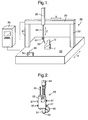
- FIG. 1 shows schematically an apparatus according to the present invention.
- the apparatus comprises a conventional CMM which includes a table 10 on which an object O to be measured is supported.
- the object is a hollow titanium alloy fan blade held in a jig J.
- the CMM has a Y-slider device 20 which is movable in the "Y" direction of the table.
- the Y-slider device has columns 21, 22 at opposing sides of the table which support a beam 23 traversing the table.
- an X-slider device 30 is mounted which is movable in the "X" direction of the table.
- the X-slider device in turn contains a quill 40 which is movable in the "Z" direction of the table.
- the lower end of the quill has a head 41 which can detachably hold a measuring probe and provides angular movement of the probe about two orthogonal axes.
- the measuring probe can be either an ultrasonic test probe 50, or a coordinate measuring stylus 60.
- the ultrasonic test probe is held by the quill, the coordinate measuring stylus being docked in a probe change station 70 of the CMM.
- the quill is drivable to the probe change station to allow the interchange of the probe and the stylus.
- the CMM can move either the probe or the stylus relative to the fan blade in three dimensions.
- the CMM further includes a programmable computer system 80 which controls the movement of the slider devices and quill, and thence the movement of the probe or stylus.
- Measurement signals from the probe or stylus pass via head 41 and quill 40 to the computer system, where they are stored in memory until needed.
- command signals pass to the probe or stylus from the computer system, to command e.g. the performance of measurements and the ejection of couplant onto the transducer of the ultrasonic test probe.
- the titanium alloy fan blade O has walls which define internal cavities. Thus, one side of the walls is formed by the external surface of the blade, and the other side of the walls is formed by internal surfaces which are inaccessible to the probe and the stylus.
- the processing operation by which the blade is produced is such that there is a degree of uncertainty in the locations of the internal surfaces relative to the external geometry of the blade.
- the ultrasonic test probe takes thickness measurements across the walls of the blade. These measurements are related to contact positions on the external surface of the blade. If the spatial coordinates of those contact positions are known, the thickness measurements can be converted into spatial coordinates for opposing positions on the internal surfaces.
- a first step is to determine the spatial coordinates of the external contact positions. This can be accomplished by defining a set of coordinate axes for the blade. Conveniently, these axes are the engine centre axis, a radial engine direction along the length of the blade, and a third axis orthogonal to the previous two axes.
- Reference markers are provided on the jig.
- the blade In use, the blade would be mounted in the engine in a predetermined relationship to the engine centre line axis and with its stacking axis aligned with an engine radial direction. The blade is held by the jig such that the reference markers have a known spatial relationship to the defined coordinate axes. Thus the spatial coordinates of the probe and stylus in a coordinate system of the engine can be calibrated with reference to the jig reference markers.
- the spatial coordinates of the probe or stylus are known in the coordinates system of the CMM, but by knowing the spatial coordinates of the reference markers in the CMM coordinates system, a simple coordinate transformation allows the CMM spatial coordinates of the probe or stylus to be converted to the engine coordinates system.
- the next step is to run coordinate measuring stylus 60 to contact positions on the external surface of the blade in order to measure the spatial coordinates of those positions. This can be accomplished using techniques and procedures known in the art.
- the stylus is then returned to probe change station 70 and ultrasonic test probe 50 is picked up by head 41.
- the probe is driven by the CMM to the contact positions previously visited by the stylus and at each a wall thickness measurement is made.
- FIG. 2 shows probe 50 in more detail.
- Probe 50 attaches to head 41 at connector 54.
- the probe has a delay line transducer 51 which emits and receives ultrasonic signals when coupled to the surface of object O.
- the axis of the probe should be perpendicular to the surface.
- head 41 provides angular movement of the probe about orthogonal axes A and B, the movement proceeds in 7.5° increments.
- the CMM can be programmed to offer the probe to the blade at an angle that is approximately perpendicular to the surface of the blade, in the majority of cases the probe measurement direction will not be precisely aligned.
- the probe has gymbal mechanisms 52 which automatically adjust the angle of the probe when it contacts the object to so that its axis is perpendicular to the contacted surface.
- one of the gymbal mechanisms is indicated.
- the other is largely hidden by the body of the probe in Figure 2 , although its eight mounts 57 are just visible.
- the adjustment effected by the gymbal mechanisms introduces a small degree of uncertainty into the actual contact position of the transducer with the object surface, but for most objects this does not lead to any significant loss in measurement accuracy because the external and internal surface curvatures are small enough such that the thickness measured post-adjustment is essentially the same as the thickness that would have been measured at the nominal contact position.
- the gymbal mechanisms can be adapted to send a signal to the computer system indicating the amount of adjustment and thereby allowing the spatial coordinates of the actual probe contact position to be calculated.
- the CMM When the CMM has positioned the probe at a contact position, and the gymbal mechanisms have taken out any probe misalignment, the CMM commands the probe to take a thickness measurement.
- a return signal from the probe to the CMM provides the thickness measurement and an indication of measurement quality. If the measurement quality is insufficient, the CMM can command the probe to take repeat measurements.
- couplant can be placed on the face of the transducer by the CMM operator before each thickness measurement, for fully automated operation of the probe, application of the couplant can be under the control of the computer system.
- the probe shown in Figure 2 has a couplant reservoir 53 which is carried by the probe.
- a stepper motor (hidden by the body of the probe in Figure 2 ) controlled by the computer system draws couplant from the reservoir and ejects it onto the transducer via hose 56 before the probe is offered to the object surface.
- a further and larger couplant reservoir (not shown) is maintained at the probe change station.
- finger 55 activates a switch (not shown) to automatically refill reservoir 53 from the larger reservoir.
- the coordinate measuring stylus and the ultrasonic test probe are used in alternation, so reservoir 53 can be refilled when the stylus is in use.
Landscapes
- Physics & Mathematics (AREA)
- General Physics & Mathematics (AREA)
- Length Measuring Devices Characterised By Use Of Acoustic Means (AREA)
- A Measuring Device Byusing Mechanical Method (AREA)
Applications Claiming Priority (2)
| Application Number | Priority Date | Filing Date | Title |
|---|---|---|---|
| GBGB0518153.2A GB0518153D0 (en) | 2005-09-07 | 2005-09-07 | Apparatus for measuring wall thicknesses of objects |
| EP06765230A EP1926969B1 (fr) | 2005-09-07 | 2006-08-08 | Procédé et appareil de mesure d épaisseur de paroi |
Related Parent Applications (1)
| Application Number | Title | Priority Date | Filing Date |
|---|---|---|---|
| EP06765230A Division EP1926969B1 (fr) | 2005-09-07 | 2006-08-08 | Procédé et appareil de mesure d épaisseur de paroi |
Publications (3)
| Publication Number | Publication Date |
|---|---|
| EP2040027A2 true EP2040027A2 (fr) | 2009-03-25 |
| EP2040027A3 EP2040027A3 (fr) | 2009-04-01 |
| EP2040027B1 EP2040027B1 (fr) | 2009-12-09 |
Family
ID=35220969
Family Applications (2)
| Application Number | Title | Priority Date | Filing Date |
|---|---|---|---|
| EP06765230A Active EP1926969B1 (fr) | 2005-09-07 | 2006-08-08 | Procédé et appareil de mesure d épaisseur de paroi |
| EP08022396A Active EP2040027B1 (fr) | 2005-09-07 | 2006-08-08 | Appareil pour mesurer l'épaisseur de paroi d'objets |
Family Applications Before (1)
| Application Number | Title | Priority Date | Filing Date |
|---|---|---|---|
| EP06765230A Active EP1926969B1 (fr) | 2005-09-07 | 2006-08-08 | Procédé et appareil de mesure d épaisseur de paroi |
Country Status (6)
| Country | Link |
|---|---|
| US (1) | US7891248B2 (fr) |
| EP (2) | EP1926969B1 (fr) |
| JP (1) | JP2009507239A (fr) |
| DE (2) | DE602006011062D1 (fr) |
| GB (1) | GB0518153D0 (fr) |
| WO (1) | WO2007028941A1 (fr) |
Families Citing this family (68)
| Publication number | Priority date | Publication date | Assignee | Title |
|---|---|---|---|---|
| DE102006031580A1 (de) | 2006-07-03 | 2008-01-17 | Faro Technologies, Inc., Lake Mary | Verfahren und Vorrichtung zum dreidimensionalen Erfassen eines Raumbereichs |
| US7921575B2 (en) * | 2007-12-27 | 2011-04-12 | General Electric Company | Method and system for integrating ultrasound inspection (UT) with a coordinate measuring machine (CMM) |
| JP5155693B2 (ja) * | 2008-02-26 | 2013-03-06 | 東芝プラントシステム株式会社 | 超音波検査装置 |
| JP5155692B2 (ja) * | 2008-02-26 | 2013-03-06 | 東芝プラントシステム株式会社 | 超音波検査装置 |
| DE102009015920B4 (de) | 2009-03-25 | 2014-11-20 | Faro Technologies, Inc. | Vorrichtung zum optischen Abtasten und Vermessen einer Umgebung |
| US9551575B2 (en) | 2009-03-25 | 2017-01-24 | Faro Technologies, Inc. | Laser scanner having a multi-color light source and real-time color receiver |
| CH701868B1 (fr) * | 2009-09-07 | 2015-01-15 | Tesa Sa | Machine à mesurer des coordonnées motorisée à programmation manuelle et méthode de contrôle d'une telle machine. |
| US9113023B2 (en) | 2009-11-20 | 2015-08-18 | Faro Technologies, Inc. | Three-dimensional scanner with spectroscopic energy detector |
| US9210288B2 (en) | 2009-11-20 | 2015-12-08 | Faro Technologies, Inc. | Three-dimensional scanner with dichroic beam splitters to capture a variety of signals |
| US9529083B2 (en) | 2009-11-20 | 2016-12-27 | Faro Technologies, Inc. | Three-dimensional scanner with enhanced spectroscopic energy detector |
| DE102009057101A1 (de) | 2009-11-20 | 2011-05-26 | Faro Technologies, Inc., Lake Mary | Vorrichtung zum optischen Abtasten und Vermessen einer Umgebung |
| US8630314B2 (en) | 2010-01-11 | 2014-01-14 | Faro Technologies, Inc. | Method and apparatus for synchronizing measurements taken by multiple metrology devices |
| DE112011100292B4 (de) | 2010-01-20 | 2016-11-24 | Faro Technologies Inc. | Anzeige für ein Koordinatenmessgerät |
| US8832954B2 (en) | 2010-01-20 | 2014-09-16 | Faro Technologies, Inc. | Coordinate measurement machines with removable accessories |
| US8615893B2 (en) | 2010-01-20 | 2013-12-31 | Faro Technologies, Inc. | Portable articulated arm coordinate measuring machine having integrated software controls |
| US8898919B2 (en) | 2010-01-20 | 2014-12-02 | Faro Technologies, Inc. | Coordinate measurement machine with distance meter used to establish frame of reference |
| US9607239B2 (en) | 2010-01-20 | 2017-03-28 | Faro Technologies, Inc. | Articulated arm coordinate measurement machine having a 2D camera and method of obtaining 3D representations |
| US9879976B2 (en) | 2010-01-20 | 2018-01-30 | Faro Technologies, Inc. | Articulated arm coordinate measurement machine that uses a 2D camera to determine 3D coordinates of smoothly continuous edge features |
| US8875409B2 (en) | 2010-01-20 | 2014-11-04 | Faro Technologies, Inc. | Coordinate measurement machines with removable accessories |
| US9163922B2 (en) | 2010-01-20 | 2015-10-20 | Faro Technologies, Inc. | Coordinate measurement machine with distance meter and camera to determine dimensions within camera images |
| DE112011100294B4 (de) | 2010-01-20 | 2019-06-13 | Faro Technologies Inc. | Tragbares Gelenkarm-Koordinatenmessgerät mit einer Multibus-Armtechnologie |
| US9628775B2 (en) | 2010-01-20 | 2017-04-18 | Faro Technologies, Inc. | Articulated arm coordinate measurement machine having a 2D camera and method of obtaining 3D representations |
| WO2011090888A2 (fr) | 2010-01-20 | 2011-07-28 | Faro Technologies, Inc. | Machine de mesure de coordonnées ayant une extrémité de sonde éclairée et procédé de fonctionnement associé |
| US8677643B2 (en) | 2010-01-20 | 2014-03-25 | Faro Technologies, Inc. | Coordinate measurement machines with removable accessories |
| EP2381212B1 (fr) * | 2010-04-26 | 2018-04-25 | Tesa Sa | Système de mesure de coordonnées pour objets à symétrie rotationnelle |
| DE102010020925B4 (de) | 2010-05-10 | 2014-02-27 | Faro Technologies, Inc. | Verfahren zum optischen Abtasten und Vermessen einer Umgebung |
| KR101126616B1 (ko) | 2010-08-31 | 2012-03-26 | 한국전력공사 | 초음파 두께 측정 장치 |
| CN103003713B (zh) | 2010-09-08 | 2015-04-01 | 法罗技术股份有限公司 | 具有投影器的激光扫描器或激光跟踪器 |
| US9168654B2 (en) | 2010-11-16 | 2015-10-27 | Faro Technologies, Inc. | Coordinate measuring machines with dual layer arm |
| US20130167647A1 (en) * | 2011-12-30 | 2013-07-04 | General Electric Company | Concurrent Multiple Characteristic Ultrasonic Inspection |
| DE102012100609A1 (de) | 2012-01-25 | 2013-07-25 | Faro Technologies, Inc. | Vorrichtung zum optischen Abtasten und Vermessen einer Umgebung |
| US8736817B2 (en) | 2012-05-25 | 2014-05-27 | Mitutoyo Corporation | Interchangeable chromatic range sensor probe for a coordinate measuring machine |
| US8817240B2 (en) | 2012-05-25 | 2014-08-26 | Mitutoyo Corporation | Interchangeable optics configuration for a chromatic range sensor optical pen |
| CN102721746A (zh) * | 2012-07-04 | 2012-10-10 | 北京理工大学 | 一种双机械手超声透射检测装置 |
| US8997362B2 (en) | 2012-07-17 | 2015-04-07 | Faro Technologies, Inc. | Portable articulated arm coordinate measuring machine with optical communications bus |
| US10067231B2 (en) | 2012-10-05 | 2018-09-04 | Faro Technologies, Inc. | Registration calculation of three-dimensional scanner data performed between scans based on measurements by two-dimensional scanner |
| US9513107B2 (en) | 2012-10-05 | 2016-12-06 | Faro Technologies, Inc. | Registration calculation between three-dimensional (3D) scans based on two-dimensional (2D) scan data from a 3D scanner |
| DE102012109481A1 (de) | 2012-10-05 | 2014-04-10 | Faro Technologies, Inc. | Vorrichtung zum optischen Abtasten und Vermessen einer Umgebung |
| US8720526B1 (en) | 2012-11-13 | 2014-05-13 | Siemens Energy, Inc. | Process for forming a long gas turbine engine blade having a main wall with a thin portion near a tip |
| CN103035156A (zh) * | 2012-11-15 | 2013-04-10 | 江苏慧硕科教仪器有限公司 | 一种教学用b型超声波原理演示实验仪 |
| US9068822B2 (en) | 2013-07-03 | 2015-06-30 | Mitutoyo Corporation | Chromatic range sensor probe detachment sensor |
| CN103837600B (zh) * | 2014-03-27 | 2017-01-18 | 苏州博昇科技有限公司 | 一种应用于电磁超声波探伤的盒式自动扫查器 |
| GB201417162D0 (en) * | 2014-09-29 | 2014-11-12 | Renishaw Plc | Inspection appartus |
| GB201417164D0 (en) | 2014-09-29 | 2014-11-12 | Renishaw Plc | Measurement Probe |
| FR3034187B1 (fr) * | 2015-03-27 | 2017-06-09 | Soc Anonyme Des Eaux Minerales D'evian Et En Abrege S A E M E | Procede et appareil de mesure d'epaisseur d'une paroi d'un recipient tel qu'un pot de yaourt |
| DE102015122844A1 (de) | 2015-12-27 | 2017-06-29 | Faro Technologies, Inc. | 3D-Messvorrichtung mit Batteriepack |
| GB2554057B (en) | 2016-07-25 | 2022-04-06 | Ele Advanced Tech Limited | A method of measuring the wall thickness of an article and an apparatus for making such measurements |
| CN106767579A (zh) * | 2016-12-22 | 2017-05-31 | 江苏阳明船舶装备制造技术有限公司 | 一种基于超声波测距技术的合拢管测量装置及测量方法 |
| GB201700534D0 (en) * | 2017-01-12 | 2017-03-01 | Rolls Royce Plc | A method of measuring fan blade picture frame width |
| JP6570600B2 (ja) | 2017-11-15 | 2019-09-04 | 株式会社東芝 | 検査システム、制御装置、角度調整方法、プログラム、および記憶媒体 |
| CN108317980B (zh) * | 2018-01-15 | 2024-06-28 | 西安工业大学 | 一种锥状回转体薄壁测厚系统及其方法 |
| CN108426504B (zh) * | 2018-03-02 | 2023-08-01 | 核工业理化工程研究院 | 测量薄壁异形管波峰顶点壁厚的三坐标测量装置及其测量方法 |
| CN108534676B (zh) * | 2018-04-20 | 2020-12-29 | 西京学院 | 一种坐标测量机测量空间内空间误差的检验方法 |
| CN109357646B (zh) * | 2018-11-30 | 2024-07-09 | 江苏集萃先进金属材料研究所有限公司 | 一种燃气涡轮发动机叶片蜡模的接触式检测装置及其方法 |
| EP3702726A1 (fr) | 2019-02-28 | 2020-09-02 | Renishaw PLC | Procédé de calibration d'une sonde ultrasonique et dispositif d'inspection correspondant |
| JP6805289B2 (ja) | 2019-05-14 | 2020-12-23 | 株式会社東芝 | 推定装置、検査システム、推定方法、角度調整方法、検査方法、プログラム、及び記憶媒体 |
| US11561204B2 (en) | 2019-08-28 | 2023-01-24 | Kabushiki Kaisha Toshiba | Display control system, inspection control system, display control method, and storage medium |
| DE102019123145A1 (de) | 2019-08-29 | 2021-03-04 | Karl Deutsch Prüf- und Meßgerätebau GmbH + Co KG | Ultraschallmesseinheit |
| EP3798629B1 (fr) | 2019-09-24 | 2024-10-23 | Kabushiki Kaisha Toshiba | Système de traitement, procédé de traitement et support d'enregistrement |
| JP7119025B2 (ja) | 2020-06-03 | 2022-08-16 | 株式会社東芝 | 制御装置、制御システム、溶接システム、制御方法、接合体の製造方法、プログラム、及び記憶媒体 |
| EP4160141A1 (fr) | 2021-09-29 | 2023-04-05 | Renishaw PLC | Procédé et appareil à ultrasons |
| EP4160142A1 (fr) | 2021-09-29 | 2023-04-05 | Renishaw PLC | Procédé ultrasonore pour l'inspection de pièce |
| CN119053834A (zh) | 2022-02-09 | 2024-11-29 | 瑞尼斯豪公司 | 超声检查探针和对应的检查方法 |
| EP4257920A1 (fr) | 2022-04-05 | 2023-10-11 | Renishaw PLC | Sonde d'inspection à ultrasons et méthode d'inspection correspondante |
| EP4227639A1 (fr) | 2022-02-09 | 2023-08-16 | Renishaw plc | Sonde d'inspection à ultrasons pour une machine-outil |
| EP4467927A1 (fr) | 2023-05-25 | 2024-11-27 | Renishaw PLC | Procédé et appareil à ultrasons |
| EP4707732A1 (fr) | 2024-09-05 | 2026-03-11 | Renishaw plc | Procédé et appareil à ultrasons |
| CN120313536B (zh) * | 2025-06-19 | 2025-09-30 | 江苏众盈精特科技有限公司 | 一种管件超声测厚装置及测厚方法 |
Citations (1)
| Publication number | Priority date | Publication date | Assignee | Title |
|---|---|---|---|---|
| US5189805A (en) | 1990-09-28 | 1993-03-02 | Mitutoyo Corporation | Coordinate measuring machine |
Family Cites Families (20)
| Publication number | Priority date | Publication date | Assignee | Title |
|---|---|---|---|---|
| US3575043A (en) * | 1969-03-17 | 1971-04-13 | Air Prod & Chem | Elongate element ultrasonic inspection system |
| DE2655179A1 (de) * | 1976-12-06 | 1978-06-08 | Kraftwerk Union Ag | Pruefkopfhalterung an einem pruefsystemtraeger, vorzugsweise fuer ultraschall-pruefkoepfe |
| JPS6033604U (ja) * | 1983-08-16 | 1985-03-07 | 出光興産株式会社 | 超音波厚さ計の媒質供給構造 |
| JPS6086462A (ja) | 1983-10-19 | 1985-05-16 | Hitachi Ltd | 超音波探傷システム |
| JPS61181368U (fr) * | 1985-04-30 | 1986-11-12 | ||
| JPS6375511A (ja) | 1986-09-18 | 1988-04-05 | Fuji Koeki:Kk | 超音波厚さ計 |
| JPH0658750A (ja) * | 1992-08-05 | 1994-03-04 | Mitsubishi Heavy Ind Ltd | 管の肉厚及び外径測定機 |
| US5274566A (en) | 1992-12-04 | 1993-12-28 | United Technologies Corporation | Aligning average axis of hollow workpiece cavity with rotary machine axis |
| US5412880A (en) * | 1993-02-23 | 1995-05-09 | Faro Technologies Inc. | Method of constructing a 3-dimensional map of a measurable quantity using three dimensional coordinate measuring apparatus |
| US5446673A (en) * | 1993-03-30 | 1995-08-29 | General Electric Company | System and method for finish machining an in-process part having an inaccessible interior cavity |
| US5576492A (en) * | 1995-01-26 | 1996-11-19 | United Technologies Corporation | Mechanical contour follower |
| US20020128790A1 (en) * | 2001-03-09 | 2002-09-12 | Donald Woodmansee | System and method of automated part evaluation including inspection, disposition recommendation and refurbishment process determination |
| DE10246781A1 (de) | 2002-10-08 | 2004-04-22 | Stotz-Feinmesstechnik Gmbh | Verfahren und Vorrichtung zur dreidimensionalen Vermessung von Objekten |
| GB2417090A (en) * | 2003-04-28 | 2006-02-15 | Stephen James Crampton | CMM arm with exoskeleton |
| US7251580B2 (en) | 2003-10-20 | 2007-07-31 | Mitutoyo Corporation | Method for measuring curved surface of workpiece, program and medium thereof |
| JP4322087B2 (ja) * | 2003-10-20 | 2009-08-26 | 株式会社ミツトヨ | ワーク曲面の測定方法とそのプログラムおよび媒体 |
| US7174788B2 (en) * | 2003-12-15 | 2007-02-13 | General Electric Company | Methods and apparatus for rotary machinery inspection |
| US7508971B2 (en) * | 2004-05-28 | 2009-03-24 | The Boeing Company | Inspection system using coordinate measurement machine and associated method |
| US7448271B2 (en) * | 2005-08-17 | 2008-11-11 | The Boeing Company | Inspection system and associated method |
| US7921575B2 (en) * | 2007-12-27 | 2011-04-12 | General Electric Company | Method and system for integrating ultrasound inspection (UT) with a coordinate measuring machine (CMM) |
-
2005
- 2005-09-07 GB GBGB0518153.2A patent/GB0518153D0/en not_active Ceased
-
2006
- 2006-08-08 WO PCT/GB2006/002927 patent/WO2007028941A1/fr not_active Ceased
- 2006-08-08 JP JP2008529674A patent/JP2009507239A/ja active Pending
- 2006-08-08 EP EP06765230A patent/EP1926969B1/fr active Active
- 2006-08-08 EP EP08022396A patent/EP2040027B1/fr active Active
- 2006-08-08 DE DE602006011062T patent/DE602006011062D1/de active Active
- 2006-08-08 DE DE602006008327T patent/DE602006008327D1/de active Active
- 2006-08-08 US US11/990,123 patent/US7891248B2/en active Active
Patent Citations (1)
| Publication number | Priority date | Publication date | Assignee | Title |
|---|---|---|---|---|
| US5189805A (en) | 1990-09-28 | 1993-03-02 | Mitutoyo Corporation | Coordinate measuring machine |
Also Published As
| Publication number | Publication date |
|---|---|
| WO2007028941A1 (fr) | 2007-03-15 |
| EP2040027B1 (fr) | 2009-12-09 |
| DE602006011062D1 (de) | 2010-01-21 |
| US7891248B2 (en) | 2011-02-22 |
| DE602006008327D1 (de) | 2009-09-17 |
| JP2009507239A (ja) | 2009-02-19 |
| EP1926969B1 (fr) | 2009-08-05 |
| GB0518153D0 (en) | 2005-10-12 |
| EP1926969A1 (fr) | 2008-06-04 |
| EP2040027A3 (fr) | 2009-04-01 |
| US20090178482A1 (en) | 2009-07-16 |
Similar Documents
| Publication | Publication Date | Title |
|---|---|---|
| US7891248B2 (en) | Apparatus for measuring wall thicknesses of objects | |
| EP2764324B1 (fr) | Procédé et dispositif de localisation d'une caractéristique d'un objet | |
| JP4275632B2 (ja) | パラレルメカニズム機構のキャリブレーション方法、キャリブレーションの検証方法、キャリブレーションの検証プログラム、データ採取方法及び空間位置補正における補正データ採取方法 | |
| EP1579168B2 (fr) | Procede d'examen d'une piece et dispositif | |
| JP7531653B2 (ja) | 表面感知デバイス(surface sensing device)を較正する方法、対応する制御コンピュータ用較正プログラムおよび対応する較正キット | |
| CN102483621B (zh) | 机床校准方法 | |
| JP4638327B2 (ja) | パラレルメカニズム装置、パラレルメカニズム装置のキャリブレーション方法、キャリブレーションプログラム、及び記録媒体 | |
| CN106471334B (zh) | 测量探头的校准 | |
| JP2809948B2 (ja) | 計算機数値制御機械用の整合装置 | |
| EP1528355B1 (fr) | Comparaison d' objets dynamique | |
| EP3402628B1 (fr) | Procédé d'étalonnage | |
| CN108700413A (zh) | 用于校准扫描探针的方法和装置 | |
| EP1792139B1 (fr) | Utilisation de sondes de mesure de surface | |
| JP2003114117A (ja) | プローブの校正方法および校正プログラム | |
| US20210225607A1 (en) | Calibrating method and calibrating system | |
| US10222193B2 (en) | Method and apparatus for inspecting workpieces | |
| JP3189500U (ja) | 物体の肉厚を測定する方法および装置 | |
| CN116045764B (zh) | 在位置确定设备中使用的表面感测装置和位置确定设备 | |
| JPH0238913A (ja) | ワークの寸法検査方法 |
Legal Events
| Date | Code | Title | Description |
|---|---|---|---|
| PUAI | Public reference made under article 153(3) epc to a published international application that has entered the european phase |
Free format text: ORIGINAL CODE: 0009012 |
|
| PUAL | Search report despatched |
Free format text: ORIGINAL CODE: 0009013 |
|
| AC | Divisional application: reference to earlier application |
Ref document number: 1926969 Country of ref document: EP Kind code of ref document: P |
|
| AK | Designated contracting states |
Kind code of ref document: A2 Designated state(s): DE FR GB |
|
| AK | Designated contracting states |
Kind code of ref document: A3 Designated state(s): DE FR GB |
|
| 17P | Request for examination filed |
Effective date: 20090313 |
|
| 17Q | First examination report despatched |
Effective date: 20090519 |
|
| GRAP | Despatch of communication of intention to grant a patent |
Free format text: ORIGINAL CODE: EPIDOSNIGR1 |
|
| GRAS | Grant fee paid |
Free format text: ORIGINAL CODE: EPIDOSNIGR3 |
|
| GRAA | (expected) grant |
Free format text: ORIGINAL CODE: 0009210 |
|
| AC | Divisional application: reference to earlier application |
Ref document number: 1926969 Country of ref document: EP Kind code of ref document: P |
|
| AK | Designated contracting states |
Kind code of ref document: B1 Designated state(s): DE FR GB |
|
| REG | Reference to a national code |
Ref country code: GB Ref legal event code: FG4D |
|
| REF | Corresponds to: |
Ref document number: 602006011062 Country of ref document: DE Date of ref document: 20100121 Kind code of ref document: P |
|
| PLBE | No opposition filed within time limit |
Free format text: ORIGINAL CODE: 0009261 |
|
| STAA | Information on the status of an ep patent application or granted ep patent |
Free format text: STATUS: NO OPPOSITION FILED WITHIN TIME LIMIT |
|
| 26N | No opposition filed |
Effective date: 20100910 |
|
| REG | Reference to a national code |
Ref country code: FR Ref legal event code: PLFP Year of fee payment: 10 |
|
| REG | Reference to a national code |
Ref country code: FR Ref legal event code: PLFP Year of fee payment: 11 |
|
| REG | Reference to a national code |
Ref country code: FR Ref legal event code: PLFP Year of fee payment: 12 |
|
| REG | Reference to a national code |
Ref country code: FR Ref legal event code: PLFP Year of fee payment: 13 |
|
| PGFP | Annual fee paid to national office [announced via postgrant information from national office to epo] |
Ref country code: DE Payment date: 20201029 Year of fee payment: 15 |
|
| REG | Reference to a national code |
Ref country code: DE Ref legal event code: R119 Ref document number: 602006011062 Country of ref document: DE |
|
| PG25 | Lapsed in a contracting state [announced via postgrant information from national office to epo] |
Ref country code: DE Free format text: LAPSE BECAUSE OF NON-PAYMENT OF DUE FEES Effective date: 20220301 |
|
| P01 | Opt-out of the competence of the unified patent court (upc) registered |
Effective date: 20230528 |
|
| PGFP | Annual fee paid to national office [announced via postgrant information from national office to epo] |
Ref country code: FR Payment date: 20230824 Year of fee payment: 18 |
|
| PG25 | Lapsed in a contracting state [announced via postgrant information from national office to epo] |
Ref country code: FR Free format text: LAPSE BECAUSE OF NON-PAYMENT OF DUE FEES Effective date: 20240831 |
|
| PGFP | Annual fee paid to national office [announced via postgrant information from national office to epo] |
Ref country code: GB Payment date: 20250826 Year of fee payment: 20 |