EP2040241A1 - Test- und Lernsystem mit mehreren Einheiten - Google Patents
Test- und Lernsystem mit mehreren Einheiten Download PDFInfo
- Publication number
- EP2040241A1 EP2040241A1 EP07017889A EP07017889A EP2040241A1 EP 2040241 A1 EP2040241 A1 EP 2040241A1 EP 07017889 A EP07017889 A EP 07017889A EP 07017889 A EP07017889 A EP 07017889A EP 2040241 A1 EP2040241 A1 EP 2040241A1
- Authority
- EP
- European Patent Office
- Prior art keywords
- fixture
- unit
- base material
- experiment
- education system
- Prior art date
- Legal status (The legal status is an assumption and is not a legal conclusion. Google has not performed a legal analysis and makes no representation as to the accuracy of the status listed.)
- Granted
Links
Images






Classifications
-
- G—PHYSICS
- G09—EDUCATION; CRYPTOGRAPHY; DISPLAY; ADVERTISING; SEALS
- G09B—EDUCATIONAL OR DEMONSTRATION APPLIANCES; APPLIANCES FOR TEACHING, OR COMMUNICATING WITH, THE BLIND, DEAF OR MUTE; MODELS; PLANETARIA; GLOBES; MAPS; DIAGRAMS
- G09B23/00—Models for scientific, medical, or mathematical purposes, e.g. full-sized devices for demonstration purposes
- G09B23/06—Models for scientific, medical, or mathematical purposes, e.g. full-sized devices for demonstration purposes for physics
- G09B23/18—Models for scientific, medical, or mathematical purposes, e.g. full-sized devices for demonstration purposes for physics for electricity or magnetism
- G09B23/183—Models for scientific, medical, or mathematical purposes, e.g. full-sized devices for demonstration purposes for physics for electricity or magnetism for circuits
-
- B—PERFORMING OPERATIONS; TRANSPORTING
- B25—HAND TOOLS; PORTABLE POWER-DRIVEN TOOLS; MANIPULATORS
- B25B—TOOLS OR BENCH DEVICES NOT OTHERWISE PROVIDED FOR, FOR FASTENING, CONNECTING, DISENGAGING, OR HOLDING
- B25B11/00—Work holders not covered by any preceding group in the subclass, e.g. magnetic work holders, vacuum work holders
- B25B11/002—Magnetic work holders
-
- G—PHYSICS
- G09—EDUCATION; CRYPTOGRAPHY; DISPLAY; ADVERTISING; SEALS
- G09B—EDUCATIONAL OR DEMONSTRATION APPLIANCES; APPLIANCES FOR TEACHING, OR COMMUNICATING WITH, THE BLIND, DEAF OR MUTE; MODELS; PLANETARIA; GLOBES; MAPS; DIAGRAMS
- G09B23/00—Models for scientific, medical, or mathematical purposes, e.g. full-sized devices for demonstration purposes
- G09B23/06—Models for scientific, medical, or mathematical purposes, e.g. full-sized devices for demonstration purposes for physics
- G09B23/18—Models for scientific, medical, or mathematical purposes, e.g. full-sized devices for demonstration purposes for physics for electricity or magnetism
- G09B23/183—Models for scientific, medical, or mathematical purposes, e.g. full-sized devices for demonstration purposes for physics for electricity or magnetism for circuits
- G09B23/185—Models for scientific, medical, or mathematical purposes, e.g. full-sized devices for demonstration purposes for physics for electricity or magnetism for circuits for building block systems
-
- G—PHYSICS
- G09—EDUCATION; CRYPTOGRAPHY; DISPLAY; ADVERTISING; SEALS
- G09B—EDUCATIONAL OR DEMONSTRATION APPLIANCES; APPLIANCES FOR TEACHING, OR COMMUNICATING WITH, THE BLIND, DEAF OR MUTE; MODELS; PLANETARIA; GLOBES; MAPS; DIAGRAMS
- G09B25/00—Models for purposes not provided for in G09B23/00, e.g. full-sized devices for demonstration purposes
- G09B25/02—Models for purposes not provided for in G09B23/00, e.g. full-sized devices for demonstration purposes of industrial processes; of machinery
- G09B25/025—Models for purposes not provided for in G09B23/00, e.g. full-sized devices for demonstration purposes of industrial processes; of machinery hydraulic; pneumatic
Definitions
- the present invention relates to a system employing a fixture which detachably secures an object to a predetermined base material, and more particularly to a system in which device constituent elements such as various types of mechanism components, sensors and the like (hereinafter, including embodiments, referred to as "unit") are appropriately combined to construct a unit constituent body and perform experiment, research, education and the like of a function or the like of the unit constituent body.
- unit device constituent elements such as various types of mechanism components, sensors and the like
- the automated device needs a mechanism section constituting an output terminal portion which imparts an objective operation to an object, an operation (interlock) converting mechanism for driving the mechanism section, and a drive mechanism for driving the operation converting mechanism.
- the automated device also needs a control system which issues an operation command to the drive source and a sensor which supplies information such as an operational state and position of an object to the control system.
- FIG. 12 shows an exemplary structure of a device proposed in the above document.
- each unit selects a predetermined rail 10X to determine an attachment position in the Y direction, and identifies a predetermined position of a specified rail 10X in the longitudinal direction of the rail 10X to provide positioning in the X direction.
- positions in the X and Y directions are determined in each unit, and each unit is coupled to constitute a specific device (mechanism) integrally.
- the constructed system in FIG. 12 is one kind of synchronization drive system in which timing of a belt conveyer is matched to a feed screw of a motor drive.
- a belt conveyer main body 16a is secured to a base 16b of a unit, and the base 16b is fixed on an arbitrary position in the longitudinal direction of a rail 10X by a bolt 16c. All bolts securing other units are shown by reference character B below.
- the rails 10X on which respective units should be attached are selected in accordance with an arrangement state of the entire mechanism constituted by the respective units as described above, and the respective units are fixed on appropriate positions along the longitudinal direction of the selected rail 10X by employing the bolt B.
- the structure is made such that a bolt through portion of a base material is an oblong hole so that the position with respect to the Y direction is finely adjustment.
- Reference numeral 17 denotes a reversible motor unit having a speed reducing mechanism which is one actuator unit
- reference numeral 18 denotes a perpendicular conversion feeding screw unit which is one type of mechanism unit for operation conversion and which is coupled with the reversible motor unit 17 having the speed reducing mechanism through a coupling 29.
- Reference numeral 19 designates a translatory table type unit which is classified as one type of output terminal unit or operation converting mechanism unit, and is coupled with the perpendicular conversion feeding screw unit 18 through a rod 20.
- Reference numeral 21 designates a reflective photoelectric sensor unit which is one type of sensor unit. The unit 21 is arranged adjacent to the translatory table type unit 19 to thereby detect movement of a translatory table of the translatory table type unit to allow its positional signal to be displayed on a display screen (not shown) of a computer.
- Reference numeral 22 designates an oil/air conversion cylinder unit which is one type of actuator
- reference numeral 23 denotes a one-way clutch unit which is an operation converting mechanism and which is coupled with the oil/air conversion cylinder unit 22 through a rod 24.
- the belt conveyer unit 16 is coupled with the one-way clutch unit 23.
- the units are respectively coupled with other units mechanically and signally to construct an integral machine system in one body, that is, a synchronization drive system of a belt conveyer. Because of the structure, when in the system, the oil/air conversion cylinder of the oil/air conversion cylinder unit 22 is driven by a signal of a photoelectric sensor of the photoelectric sensor unit 21, the belt conveyer of the belt conveyer unit 16 is driven for only one-way part every time.
- these units are coupled with a predetermined control circuit of a control panel 11 to cause the respective constituent units to perform predetermined operations.
- a predetermined control circuit of a control panel 11 it is constructed such that a user may construct a desired control system by connecting a predetermined line part of a plurality of relay terminals arranged or such that they are connected to an assembled relay circuit to control the mechanism based on a predetermined control order.
- the reversible motor unit 17 having the speed reducing mechanism is operated by the operation signal of the control system constructed as describe above, and its driving force becomes linear motion in the perpendicular conversion feeding screw unit 18.
- the reversible motor unit 17 having the speed reducing mechanism by allowing the reversible motor unit 17 having the speed reducing mechanism to be connected to a timer 25, the reversible motor of the motor unit 17 undergoes a phase reversal at preset time to allow the feed screw of the same unit 18 to advance and retreat.
- the operation of the feed screw is transmitted to the translatory table of the translatory table type unit 19 through the rod 20 to allow the table to advance and retreat.
- the operation state of the table is detected by the reflective photoelectric sensor unit 21, and its positional signal is outputted to a computer or the like to be employed as a timing signal which drives the belt conveyer unit. Further, it is possible to additionally incorporate the timer 25 in the relay circuit to alter control by a method of controlling the circuit's ON/OFF.
- the drive force of the oil/air conversion cylinder unit 22 is transmitted to the one-way clutch unit 23 through the rod 22 to provide intermittent operation, and by this intermittent operation, the belt conveyer of the belt conveyer unit 16 is intermittently operated.
- each unit If the arrangement of each unit is not appropriately performed, for example, loss may be generated in transmission of drive force from a drive unit to another unit, or if it is a translatory drive, a problem may occur such as a drift in the drive direction is generated. Further, in the case of the sensor unit, an operation state of another unit cannot be measured accurately if a sensing position is not appropriate, and consequently, timing of a signal becomes inappropriate.
- attachment and detachment of a unit to and from an attachment object such as the rail 10X is easy.
- attachment and detachment is easy means that operation of attachment and detachment is simple, that a special tool is not necessary for the operation, and that a large amount of force is not necessary.
- attachment/detachment and movement of a unit can be performed in a short period of time without necessitating a special skill, tool, and a large amount of force in the operation.
- an experiment and education system in which a plurality of units that are a mechanical element, an optical element, a measurement element such as a sensor, and the like, are combined to form a unit constituent body that is a machinery having a specific function in their entirety and also to implement experiment and education regarding the function of the unit constituent body.
- Respective units are constructed so as to be appropriately disposed on arbitrary positions on a magnetic base material, and the respective units are detachably secured to the base material on the arbitrary positions by means of fixtures which employ magnetic force, so that the units are secured to the base material so as to be mutually adjusted in position to thereby constitute the unit constituent body.
- a magnetic flat plate made of a ferrous metal is employed as a base material for arranging units, and units having predetermined functions are arranged on the base material to form a unit constituent body as a machinery having a specific object in their entirety.
- the respective units are secured to the base material on predetermined positions by employing fixtures which are detachably adsorbed to the base material by magnetic force.
- the respective units are fixed in such a way that positional adjustment thereof is possible to form a unit constituent body that is a desired machinery. Consequently, experiment and research regarding the function of the unit constituent body are conducted, and research regarding change or the like in function and properties of the entire unit constituent body is done, for example, by changing a predetermined unit into another unit.
- FIGS. 1 to 4 show the structure of a fixture of a unit according to a first embodiment of the present invention.
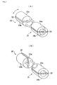
- FIGS. 1 and 2 are views showing in principle the structure of a fixture's detachable mechanism to be accommodated in the fixture according to the first embodiment.
- the detachable mechanism employs a permanent magnet, and as described later, a permeation state of magnetic force lines of the permanent magnet is controlled so that the mechanism is attached to and detached from a base material that is an adsorption object.
- the detachable mechanism is composed of two blocks 30 and 31 as apparent from the drawings, and both the blocks 30, 31 are constructed such that they can relatively rotate about their axial center. In the following description, the case where the block 30 is rotated is exemplified and explained. In the illustrated structure, the blocks 30, 31 are all formed cylindrically.
- Reference numeral 32 is a permanent magnet formed into a plate shape, which is constructed as a magnet having a strong force of the extent that the entire fixture can be firmly adsorbed and secured to the base material.
- block constituent bodies 33a, 33b made of a magnetism permeable material are arranged and fixed so as to sandwiching the permanent magnet 32 therebetween, to thereby integrally construct the cylindrical first block 30 in their entirety.
- the permanent magnet 32 is arranged inside the block 30 such that respective poles are positioned at both end surfaces of the cylindrical first block 30.
- the second block 31 is composed of block constituent bodies 34a, 34b having permeability which is similar to that of the first block 30 and a spacer 35 sandwiched by these block constituent bodies 34a, 34b.
- the second block 31 is constructed so as to be cylindrical, having substantially the same structure as that of the first block 30 in outward form.
- the spacer 35 is a non-magnetic material which is different from the permanent magnet 32. Accordingly, the spacer will be called a non-magnetic spacer.
- One end surface of the above-described first block 30 and one end surface of the second block 31 are arranged in intimate contact with each other in a state in which the first block 30 can rotate about its axial center.
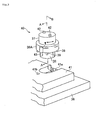
- FIG. 1A when end surfaces of the respective block constituent bodies 33a, 33b of the first block and end surfaces of the respective block constituent bodies 34a, 34b of the second block are in a state in intimate contact with one another integrally, these respective block constituent bodies become one body to construct one magnetism permeable path. Consequently, magnetic force lines of the permanent magnet 32 permeate a base material 36 that is the fixing object as shown in FIG. 2 . That is, when the respective blocks 30, 31 are in a state of FIG. 1A , the detachable mechanism composed of the blocks 30, 31 are firmly adsorbed to the base material 36.
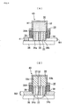
- FIGS. 3 and 4 illustrate a fixture constructed to incorporate an adsorption mechanism shown in FIGS. 1 and 2 .
- Reference numeral 40 denotes this fixture
- reference numeral 37 denotes a rotation casing
- reference numeral 38 denotes a fixing casing.
- the rotation casing 37 is constructed so as to be rotatable with respect to the fixing casing 38.
- a pressing portion 38A protruding like a flange is formed on the outer periphery of the upper part of the fixing casing 38.
- a plurality of members for preventing slip hereinafter referred to as "slip preventing members" 39 made of a flexible material such as rubber are embedded in the circumferential direction of the bottom surface of the pressing portion 38A toward the fixing object which will be described later herein.
- a permanent magnet 32 having a plate-like configuration similar to that shown in FIGS. 1 and 2 and the block constituent bodies 33a, 33b are arranged and fixed such that the block constituent bodies 33a, 33b sandwich the permanent magnet 32. That is, the first block 30 shown in FIGS. 1 and 2 is secured inside the rotation casing 37, and the first block 30 is constructed to rotate together with the rotation casing 37.
- the second block 31 composed of the non-magnetic spacer 35 sandwiched by the block constituent bodies 34a, 34b is formed, arranged, and fixed inside this casing.
- pins 42 protrude from the top portion of the rotation casing 37 as grips for rotating the rotation casing 37, these pins 42 are omitted in FIG. 4 .
- the permanent magnet 32 of the first block 30 and the non-magnetic spacer 35 of the second block 31 are perpendicular to each other in FIG. 4A , and as illustrated, the block constituent bodies 33a, 33b of the first block and the block constituent bodies 34a, 34b of the second block inside the fixing casing 38 are not integrated. Accordingly, magnetic force lines of the permanent magnet 32 do not reach the bottom end of the fixing block 31 side, and consequently, the fixture is not adsorbed to the base material 36 to be in a freely movable state.
- reference numeral 41 denotes a base of a mechanism constituent unit, and respective mechanisms are fixedly secured to the base 41.
- a notch 41a for mounting each fixture 40 is formed on the base 41 of each unit.
- the rotation casing 37 of the fixture 40 arranged on the notch 41a is rotated 90 degrees in a lock direction.
- the block constituent bodies 33a, 33b of the first block 30 and the block constituent bodies 34a, 34b of the second block 31 are integrated, and magnetic force of the permanent magnet 32 permeates the base material 36, so that the fixture 40 is firmly adsorbed to the base material 36.
- the fixture 40 since clearance W1 between the bottom end portion of the slip preventing members 39 of the fixture 40 and the base material 36 is set at a value smaller than thickness W2 of the base 40, the fixture 40 is firmly adsorbed to the base material 36, so that the slip preventing members 39 are deformed for canceling this difference to be pressed against the base 41 as shown in FIG. 4B . More specifically, the fixture 40 itself is firmly and fixedly secured to the base material 36, and the base 41 is firmly secured to a predetermined position by the fixture 40 through the slip preventing members 39. In the case where the fine adjustment of the position of the base 41 is performed, the fixed state is completely released by allowing once the rotation casing 37 to rotate 90 degrees to an unlock side. Therefore, in this state, the arrangement position of the base 41 is finely adjusted, and after the fine adjustment is finished, the rotation casing 37 is rotated to the lock side again to firmly fixing the base.
- a pin 43 protrudes from the fixture 40, and a pin through hole 41b into which the pin 43 is inserted and positioned is formed on the base 41.
- the pin 43 is inserted into the pin through hole 41b so as to make the operation of the fixture 40 easy.
- the rotation casing 37 in an upper part can readily be rotated to be in the unlock state.
- the fixing casing 38 is not adsorbed to the base material 36 when the rotation of the rotation casing 37 is started, which may cause the fixing casing 38 to be rotated in synchronization with the rotation casing 37 or may change the position of the entire fixture 40.
- consideration is necessary for a user wherein the fixing casing 38 is firmly fixed by one hand and in this state the rotation casing 37 is carefully rotated. In this case, when the pin 43 meshes with the pin through hole 41b, the rotation casing 37 is rotated by one hand regardless of whether it is in the lock state or the unlock state, so that the fixture 40 can be easily attached and detached.
- FIGS. 5 and 6 illustrate a fixture 43 according to a second embodiment of the present invention.
- FIG. 5 shows a constituting state of a detachable mechanism to be accommodated in the fixture 43, wherein reference characters 44a, 44b designate block constituent bodies made of a magnetism permeable material, and reference characters 45a, 45b designate non-magnetic spacers sandwiched by these block constituent bodies 44a, 44b.
- Reference numeral 46 designates a permanent magnet, which is formed into a cylindrical shape having an axial center in the direction perpendicular to the drawing. Respective poles are formed in the diametrical direction of the cylindrical shape, and the permanent magnet 46 can rotate about the axial center inside this block.
- the poles of the permanent magnet 46 are positioned to face the respective block constituent bodies 44a, 44b, and as a result, magnetic force lines of the permanent magnet 46 permeate the block constituent bodies 44a, 44b through the base material 36. That is, when the poles of the permanent magnet 46 are positioned horizontally as illustrated, the detachable mechanism is firmly adsorbed and secured to the base material 36. Further, when the respective poles are positioned in the non-magnetic spacer side by allowing the permanent magnet 46 to rotate 90 degrees from this state, the magnetic force lines do not escape from the block constituent bodies 44a, 44b, so that the adsorption force of the detachable mechanism is lost.
- the fixture 43 of FIGS. 6A and 6B shows a fixture constructed based on the above-described structure.
- Reference numeral 47 denotes a lever for allowing the permanent magnet 46 forming a part of this fixture 43 to rotate. By operating the lever 47, the poles of the permanent magnet 46 are altered 90 degrees to attach and detach the fixture 43 to and from the base material 36 as shown in FIG. 5 .
- Reference character 43A designates pressing portions protruding from a side wall portion of the fixture main body 43 formed into a substantially rectangular. These pressing portions 43A are fixedly secured to the fixture main body 43 in such a manner that positional adjustment in the vertical direction is possible by means of a screw 43Aa. Slip preventing members 39 protrude from the pressing portion 43Aa toward a fixing object, similarly to the fixture 40.
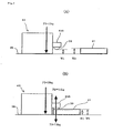
- FIG. 7 schematically shows the structure of the fixture.
- adsorption force F1 by the magnetic force of the fixture 43 is 15 kg.
- FIG. 8 shows a fixture according to a third embodiment.
- Magnetic force lines of a magnet are controlled to attach or detach a fixture to and from the base material 36 in any of the above-described embodiments.
- a fixture is separated from the base material 36 forcibly by physical force against adsorption force of a magnet.
- a permanent magnet (horseshoe-shaped magnet in the case of the drawing) 60 is accommodated in the fixture 43, and the fixture 43 is adsorbed to the base material 36 by the permanent magnet 60.
- Reference numeral 61 denotes a lever, which is configured to rotate about a rotation axial center L thereof. Further, the distance from a bottom end 61a of the lever 61 to the rotation axial center L is set to a value longer than the distance from the rotation axial center L to the base material 36. As a consequence, when the fixture 43 is adsorbed to the base material 36 by the magnetic force of the permanent magnet 60, the lever 61 is positioned at a tilt angle as shown in FIG. 8A .
- the entire fixture 43 floats against the adsorption force of the permanent magnet 60 by the rotation of the bottom end of the lever 61 in which the rotation arm length is set to a length longer than the distance from the rotation axial center L to the base material 36, so that the fixed state of the base 41 is released.
- the adsorption force by the magnetic force is inversely proportional to the second power of the distance, the adsorption force of the entire fixture 43 decreases drastically only by separating the fixture 43 from the base material 36 a little.
- the entire fixture 43 is separated from the base material 36 in the order of 1 to 2 mm, so that the fixture 43 can be easily removed from the base material 36.
- This embodiment is an embodiment which can be said to be a modified example of the third embodiment.
- means for spacing the fixture 43 apart from the base material 36 is formed directly on the pressing portion 43A instead of the lever 61.
- a screw (male thread) screwing a female thread portion 62 (illustrated structure) protruding from the pressing portion 43A is rotated so that the fixture 36 can be fixedly secured (the state of FIG. 9A ) or can be spaced apart (the state of FIG. 9B ).
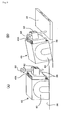
- FIGS. 10A and 10B illustrate a state in which a plurality of mechanism constituent units are coupled by employing the fixture 43 of the second embodiment.
- reference character U1 designates an actuator unit which supplies drive force to another unit.
- a geared motor M for generating the drive force is fixed on a base 41A, and a coupling member 50A constituting a part of a coupling mechanism 50 is provided on the geared motor M.
- Reference character U2 designates a mechanism unit, which is constructed so as to perform a predetermined operation by employing the drive force supplied from the actuator unit U1.
- the illustrated structure includes a coupling member 50B, a screw rod 48 to be coupled with the coupling member 50B, and a slider 49 which screws the screw rod 48.
- the actuator unit U1 is arranged on a predetermined position of the base material 36.
- the pressing portion 43b is positioned on an end edge portion of the base 41A of the actuator unit U1 with a first fixture 43 (hereinafter designated by reference numeral 43-1) unlocked (in a state in which the lever 47 is positioned in Y side in FIG. 6A ), so that, in this state, the lever 47 is rotated in the X direction.
- the fixture 43-1 is firmly adsorbed and fixed to the base material 36 side to secure the base 41A of the actuator unit U1 to the base material 36.
- the mechanism unit U2 is arranged on an appropriate position such that the coupling member 50 of the mechanism unit U2 is correctly coupled with the coupling member 50A of the actuator unit U1.
- the base 41B of the mechanism unit U2 is fixed on the base material 36 by means of a fixture 43-3 through an operation similar to the fixing case of the actuator unit U1. Further, similarly to the actuator unit U2, in a case where firm fixing is necessary furthermore, fixing is performed by employing a next fixture 43-4 or the like as the need arises.
- a connecting rod 51 is coupled with the slider 49 of the mechanism unit U2.
- the rotation drive force from the actuator unit U1 is conveyed to the screw rod 48 of the mechanism unit U2 through the coupling mechanism 50.
- the rotation of the screw rod 48 allows the slider 49 which screws the screw rod 48 to displace to the axial center direction of the screw rod 48.
- This displacement is conveyed, for example, to another mechanism unit as a linear motion through the connecting rod 51.
- the reaction force (counter torque) against the rotation torque of the geared motor M of the actuator unit U1 the reaction force of the linear motion with respect to another unit through the connecting rod 15, and the like are added to the respective units U1, U2.
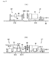
- FIG. 11 illustrates an example of another mechanism constituent unit.
- the unit designated by arrow U3 in FIG. 11A is one type of mechanism unit, and linear motion in the X1-Y1 direction from an actuator unit performing reciprocating motion is conveyed to a rack 51b through a joint 51a.
- This linear motion is conveyed to a pinion 51c which meshes with the rack 51b as rotational motion, and is conveyed to another unit through an output gear 51d coupled with a pinion 51c as rotational motion.
- reaction force of linear motion in the X1-Y1 direction, counter torque with respect to rotation torque of the output gear 51d, or the like operates as a force for displacing the base 41.
- a unit designated by reference character U4 is one type of mechanism unit, which receives drive force outputted from another unit by an input gear 52a, and allows rotational force of the input gear 52a to be conveyed to a turn table 52b by a rotation axis changing mechanism such as, for example, a bevel gear.
- a rotation axis changing mechanism such as, for example, a bevel gear.
- a unit designated by reference character U5 is one type of actuator unit, wherein reference character 53a denotes an air cylinder, which is constructed so as to be rotatable about a hinge 53b in an X4-Y4 direction.
- a rod 53c expands and contracts in an X3-Y3 direction in the air cylinder 53a itself. Therefore, when the air cylinder 53a is operated, reaction force of the expansion and contraction operation of the cylinder rod 53c in the X3-Y3 direction functions as a force for displacing the base 41 in either direction between the X4-Y4 direction.
- the fixture according to the present invention can fix the base of a unit firmly in any direction uniformly.
- each unit for constituting a unit constituent body that is a device for achieving a specific objective can be detachably secured easily to a base material by means of a fixture employing magnet.
- each unit can be fixed on a desired position of a base material easily and firmly while its positional adjustment is possible, and it is also possible to easily perform adjustment, experiment, education, and the like of the structure of the device as the unit constituent body.
- magnetic force lines of a magnet having strong magnetic force and attached to a fixture is controlled for example by a lever operation, or rotation operation of a rotation portion, or on/off operation of a power source in the case of an electromagnet.
- principle of lever, rotation operation of screw, or the like is used to forcibly space the fixture apart from the base material. This makes it possible to easily attach and detach the fixture to and from the base material without using a special tool and requiring a strong force. Consequently, the position of a fixing object can also be finely adjusted with ease.
- the fixing object is firmly sandwiched by the pressing portion of the fixture and the base material to which the fixture main body has been adsorbed by magnetic force.
- the fixing object is firmly fixed on a predetermined position of the base material, so that each unit can sufficiently maintain a predetermined mechanism against the reaction force of a drive force, vibration or the like, without so-called backlash, for a long period of time.
- arranging and fixing the mechanism constituent unit is exemplified in an automated mechanism research education device.
- it can be utilized in all devices in which a desired member or device has to be arranged firmly on a predetermined position on a placement surface which faces the base material 36 and which has permeability.
Landscapes
- Engineering & Computer Science (AREA)
- Physics & Mathematics (AREA)
- General Physics & Mathematics (AREA)
- Business, Economics & Management (AREA)
- Theoretical Computer Science (AREA)
- Educational Technology (AREA)
- Educational Administration (AREA)
- Mathematical Analysis (AREA)
- Mathematical Physics (AREA)
- Pure & Applied Mathematics (AREA)
- Mathematical Optimization (AREA)
- Computational Mathematics (AREA)
- Algebra (AREA)
- Mechanical Engineering (AREA)
- Toys (AREA)
Priority Applications (1)
| Application Number | Priority Date | Filing Date | Title |
|---|---|---|---|
| EP07017889.2A EP2040241B1 (de) | 2007-09-12 | 2007-09-12 | Test- und Lernsystem mit mehreren Einheiten |
Applications Claiming Priority (1)
| Application Number | Priority Date | Filing Date | Title |
|---|---|---|---|
| EP07017889.2A EP2040241B1 (de) | 2007-09-12 | 2007-09-12 | Test- und Lernsystem mit mehreren Einheiten |
Publications (2)
| Publication Number | Publication Date |
|---|---|
| EP2040241A1 true EP2040241A1 (de) | 2009-03-25 |
| EP2040241B1 EP2040241B1 (de) | 2015-12-02 |
Family
ID=38606491
Family Applications (1)
| Application Number | Title | Priority Date | Filing Date |
|---|---|---|---|
| EP07017889.2A Ceased EP2040241B1 (de) | 2007-09-12 | 2007-09-12 | Test- und Lernsystem mit mehreren Einheiten |
Country Status (1)
| Country | Link |
|---|---|
| EP (1) | EP2040241B1 (de) |
Cited By (6)
| Publication number | Priority date | Publication date | Assignee | Title |
|---|---|---|---|---|
| CN109114077A (zh) * | 2018-07-27 | 2019-01-01 | 武汉船用机械有限责任公司 | 一种磁力固定机构 |
| CN109863638A (zh) * | 2017-07-11 | 2019-06-07 | 株式会社Lg化学 | 用于二次电池测试的固定装置 |
| EP3512030A4 (de) * | 2017-07-11 | 2019-10-30 | LG Chem, Ltd. | Befestigungsvorrichtung zum testen einer sekundärbatterie |
| CN111554174A (zh) * | 2020-05-27 | 2020-08-18 | 山东省城乡规划设计研究院 | 一种用于建筑设计的沙盘模型连接装置 |
| CN112116853A (zh) * | 2020-09-10 | 2020-12-22 | 燕山大学 | 一种旋转磁场实验装置 |
| CN113458659A (zh) * | 2020-03-31 | 2021-10-01 | 株式会社神户制钢所 | 导轨装置、焊接装置以及导轨装置的拆卸方法 |
Families Citing this family (1)
| Publication number | Priority date | Publication date | Assignee | Title |
|---|---|---|---|---|
| CN108335586B (zh) * | 2018-05-16 | 2020-03-06 | 李心一 | 一种物理多功能实验系统 |
Citations (4)
| Publication number | Priority date | Publication date | Assignee | Title |
|---|---|---|---|---|
| GB1217885A (en) | 1967-02-10 | 1970-12-31 | Intertrading Corp Establishmen | Electrical constructional kits |
| US6471273B1 (en) | 2000-08-14 | 2002-10-29 | Industrial Magnetics, Inc. | Lifting magnet with roller cam release mechanism |
| WO2003009972A2 (en) * | 2001-07-26 | 2003-02-06 | Stäubli Tec-Systems GmbH | Magnetic clamping device and method for detecting and controlling an operating state of a magnetic clamping device |
| FR2872077A1 (fr) | 2004-06-24 | 2005-12-30 | Pass Technologies Sarl | Demi-pince aimantee multi-usage de fixation |
-
2007
- 2007-09-12 EP EP07017889.2A patent/EP2040241B1/de not_active Ceased
Patent Citations (4)
| Publication number | Priority date | Publication date | Assignee | Title |
|---|---|---|---|---|
| GB1217885A (en) | 1967-02-10 | 1970-12-31 | Intertrading Corp Establishmen | Electrical constructional kits |
| US6471273B1 (en) | 2000-08-14 | 2002-10-29 | Industrial Magnetics, Inc. | Lifting magnet with roller cam release mechanism |
| WO2003009972A2 (en) * | 2001-07-26 | 2003-02-06 | Stäubli Tec-Systems GmbH | Magnetic clamping device and method for detecting and controlling an operating state of a magnetic clamping device |
| FR2872077A1 (fr) | 2004-06-24 | 2005-12-30 | Pass Technologies Sarl | Demi-pince aimantee multi-usage de fixation |
Cited By (9)
| Publication number | Priority date | Publication date | Assignee | Title |
|---|---|---|---|---|
| CN109863638A (zh) * | 2017-07-11 | 2019-06-07 | 株式会社Lg化学 | 用于二次电池测试的固定装置 |
| EP3512030A4 (de) * | 2017-07-11 | 2019-10-30 | LG Chem, Ltd. | Befestigungsvorrichtung zum testen einer sekundärbatterie |
| US11041909B2 (en) | 2017-07-11 | 2021-06-22 | Lg Chem, Ltd. | Fixing device for secondary battery test |
| CN109863638B (zh) * | 2017-07-11 | 2022-03-04 | 株式会社Lg化学 | 用于二次电池测试的固定装置 |
| CN109114077A (zh) * | 2018-07-27 | 2019-01-01 | 武汉船用机械有限责任公司 | 一种磁力固定机构 |
| CN109114077B (zh) * | 2018-07-27 | 2020-07-17 | 武汉船用机械有限责任公司 | 一种磁力固定机构 |
| CN113458659A (zh) * | 2020-03-31 | 2021-10-01 | 株式会社神户制钢所 | 导轨装置、焊接装置以及导轨装置的拆卸方法 |
| CN111554174A (zh) * | 2020-05-27 | 2020-08-18 | 山东省城乡规划设计研究院 | 一种用于建筑设计的沙盘模型连接装置 |
| CN112116853A (zh) * | 2020-09-10 | 2020-12-22 | 燕山大学 | 一种旋转磁场实验装置 |
Also Published As
| Publication number | Publication date |
|---|---|
| EP2040241B1 (de) | 2015-12-02 |
Similar Documents
| Publication | Publication Date | Title |
|---|---|---|
| EP2040241B1 (de) | Test- und Lernsystem mit mehreren Einheiten | |
| US7963771B2 (en) | Experiment and education system employing a plurality of units | |
| CN105940440B (zh) | 用于平铺式显示器的定位和对齐装置 | |
| CN104937483B (zh) | 校正光学装置、图像偏转校正装置和成像装置 | |
| US8850886B2 (en) | Electromechanic microsensor | |
| EP3018563B1 (de) | Bauteil zur aufhängung einer haptischen berührungstafelbaugruppe | |
| CN110233077A (zh) | 一种旋钮开关 | |
| KR20100028041A (ko) | 전기기계 모터, 특히 압전 마이크로스테퍼 구동장치 | |
| CN113167602B (zh) | 绝对编码器 | |
| CN101409025B (zh) | 使用多个单元的实验和教学系统 | |
| JP7507941B2 (ja) | アブソリュートエンコーダ | |
| KR20040004727A (ko) | 구면모터 장치 | |
| KR101341614B1 (ko) | 복수 개의 유닛들을 채용하는 실험 및 교육 장치 | |
| US10510944B2 (en) | Vibration actuator reduced in cost and size, and electronic device | |
| JPH10177036A (ja) | 電気回路基板のテスト用アダプター及び両面回路基板のためのテスト固定装置 | |
| JP6021559B2 (ja) | 振動型駆動装置及び撮像装置 | |
| JP2007279494A (ja) | 複数のユニットを用いた実験・教育システム | |
| KR20150134749A (ko) | 차분력에 의해 구동되는 탄성힌지 기반 적층형 2축 병렬 스테이지 | |
| HK1126566B (en) | Experiment and education system employing a plurality of units | |
| CN116829311B (zh) | 六自由度运动机构 | |
| JP2009128629A (ja) | ズームレンズユニット、ズームレンズユニット用鏡筒、撮像装置、カメラ、携帯端末装置および携帯電話 | |
| JP2009281497A (ja) | マグネット板及びこれを用いた回転動力伝達装置 | |
| KR20170002836U (ko) | 실습기자재용 클램핑장치 | |
| JP3721969B2 (ja) | ステージ装置 | |
| KR101125541B1 (ko) | 실습기자재용 클램핑 장치 |
Legal Events
| Date | Code | Title | Description |
|---|---|---|---|
| PUAI | Public reference made under article 153(3) epc to a published international application that has entered the european phase |
Free format text: ORIGINAL CODE: 0009012 |
|
| AK | Designated contracting states |
Kind code of ref document: A1 Designated state(s): AT BE BG CH CY CZ DE DK EE ES FI FR GB GR HU IE IS IT LI LT LU LV MC MT NL PL PT RO SE SI SK TR |
|
| AX | Request for extension of the european patent |
Extension state: AL BA HR MK RS |
|
| 17P | Request for examination filed |
Effective date: 20090903 |
|
| 17Q | First examination report despatched |
Effective date: 20091005 |
|
| AKX | Designation fees paid |
Designated state(s): DE GB |
|
| GRAP | Despatch of communication of intention to grant a patent |
Free format text: ORIGINAL CODE: EPIDOSNIGR1 |
|
| INTG | Intention to grant announced |
Effective date: 20150617 |
|
| GRAS | Grant fee paid |
Free format text: ORIGINAL CODE: EPIDOSNIGR3 |
|
| GRAA | (expected) grant |
Free format text: ORIGINAL CODE: 0009210 |
|
| AK | Designated contracting states |
Kind code of ref document: B1 Designated state(s): DE GB |
|
| REG | Reference to a national code |
Ref country code: GB Ref legal event code: FG4D |
|
| REG | Reference to a national code |
Ref country code: DE Ref legal event code: R096 Ref document number: 602007044064 Country of ref document: DE |
|
| REG | Reference to a national code |
Ref country code: DE Ref legal event code: R097 Ref document number: 602007044064 Country of ref document: DE |
|
| PLBE | No opposition filed within time limit |
Free format text: ORIGINAL CODE: 0009261 |
|
| STAA | Information on the status of an ep patent application or granted ep patent |
Free format text: STATUS: NO OPPOSITION FILED WITHIN TIME LIMIT |
|
| PGFP | Annual fee paid to national office [announced via postgrant information from national office to epo] |
Ref country code: GB Payment date: 20160929 Year of fee payment: 10 |
|
| 26N | No opposition filed |
Effective date: 20160905 |
|
| GBPC | Gb: european patent ceased through non-payment of renewal fee |
Effective date: 20170912 |
|
| PG25 | Lapsed in a contracting state [announced via postgrant information from national office to epo] |
Ref country code: GB Free format text: LAPSE BECAUSE OF NON-PAYMENT OF DUE FEES Effective date: 20170912 |
|
| PGFP | Annual fee paid to national office [announced via postgrant information from national office to epo] |
Ref country code: DE Payment date: 20190926 Year of fee payment: 13 |
|
| REG | Reference to a national code |
Ref country code: DE Ref legal event code: R119 Ref document number: 602007044064 Country of ref document: DE |
|
| PG25 | Lapsed in a contracting state [announced via postgrant information from national office to epo] |
Ref country code: DE Free format text: LAPSE BECAUSE OF NON-PAYMENT OF DUE FEES Effective date: 20210401 |