EP2040320A1 - Elektrische Speichervorrichtung - Google Patents
Elektrische Speichervorrichtung Download PDFInfo
- Publication number
- EP2040320A1 EP2040320A1 EP20080164586 EP08164586A EP2040320A1 EP 2040320 A1 EP2040320 A1 EP 2040320A1 EP 20080164586 EP20080164586 EP 20080164586 EP 08164586 A EP08164586 A EP 08164586A EP 2040320 A1 EP2040320 A1 EP 2040320A1
- Authority
- EP
- European Patent Office
- Prior art keywords
- negative
- electrode
- mixture layer
- electrode mixture
- positive
- Prior art date
- Legal status (The legal status is an assumption and is not a legal conclusion. Google has not performed a legal analysis and makes no representation as to the accuracy of the status listed.)
- Granted
Links
Images




Classifications
-
- H—ELECTRICITY
- H01—ELECTRIC ELEMENTS
- H01G—CAPACITORS; CAPACITORS, RECTIFIERS, DETECTORS, SWITCHING DEVICES, LIGHT-SENSITIVE OR TEMPERATURE-SENSITIVE DEVICES OF THE ELECTROLYTIC TYPE
- H01G11/00—Hybrid capacitors, i.e. capacitors having different positive and negative electrodes; Electric double-layer [EDL] capacitors; Processes for the manufacture thereof or of parts thereof
- H01G11/66—Current collectors
- H01G11/72—Current collectors specially adapted for integration in multiple or stacked hybrid or EDL capacitors
-
- H—ELECTRICITY
- H01—ELECTRIC ELEMENTS
- H01M—PROCESSES OR MEANS, e.g. BATTERIES, FOR THE DIRECT CONVERSION OF CHEMICAL ENERGY INTO ELECTRICAL ENERGY
- H01M10/00—Secondary cells; Manufacture thereof
- H01M10/05—Accumulators with non-aqueous electrolyte
- H01M10/052—Li-accumulators
- H01M10/0525—Rocking-chair batteries, i.e. batteries with lithium insertion or intercalation in both electrodes; Lithium-ion batteries
-
- H—ELECTRICITY
- H01—ELECTRIC ELEMENTS
- H01M—PROCESSES OR MEANS, e.g. BATTERIES, FOR THE DIRECT CONVERSION OF CHEMICAL ENERGY INTO ELECTRICAL ENERGY
- H01M10/00—Secondary cells; Manufacture thereof
- H01M10/04—Construction or manufacture in general
- H01M10/0413—Large-sized flat cells or batteries for motive or stationary systems with plate-like electrodes
-
- H—ELECTRICITY
- H01—ELECTRIC ELEMENTS
- H01M—PROCESSES OR MEANS, e.g. BATTERIES, FOR THE DIRECT CONVERSION OF CHEMICAL ENERGY INTO ELECTRICAL ENERGY
- H01M10/00—Secondary cells; Manufacture thereof
- H01M10/05—Accumulators with non-aqueous electrolyte
- H01M10/058—Construction or manufacture
-
- H—ELECTRICITY
- H01—ELECTRIC ELEMENTS
- H01M—PROCESSES OR MEANS, e.g. BATTERIES, FOR THE DIRECT CONVERSION OF CHEMICAL ENERGY INTO ELECTRICAL ENERGY
- H01M4/00—Electrodes
- H01M4/02—Electrodes composed of, or comprising, active material
- H01M4/13—Electrodes for accumulators with non-aqueous electrolyte, e.g. for lithium-accumulators; Processes of manufacture thereof
-
- H—ELECTRICITY
- H01—ELECTRIC ELEMENTS
- H01M—PROCESSES OR MEANS, e.g. BATTERIES, FOR THE DIRECT CONVERSION OF CHEMICAL ENERGY INTO ELECTRICAL ENERGY
- H01M4/00—Electrodes
- H01M4/02—Electrodes composed of, or comprising, active material
- H01M4/13—Electrodes for accumulators with non-aqueous electrolyte, e.g. for lithium-accumulators; Processes of manufacture thereof
- H01M4/137—Electrodes based on electro-active polymers
-
- H—ELECTRICITY
- H01—ELECTRIC ELEMENTS
- H01M—PROCESSES OR MEANS, e.g. BATTERIES, FOR THE DIRECT CONVERSION OF CHEMICAL ENERGY INTO ELECTRICAL ENERGY
- H01M4/00—Electrodes
- H01M4/02—Electrodes composed of, or comprising, active material
- H01M4/36—Selection of substances as active materials, active masses, active liquids
- H01M4/362—Composites
- H01M4/366—Composites as layered products
-
- H—ELECTRICITY
- H01—ELECTRIC ELEMENTS
- H01M—PROCESSES OR MEANS, e.g. BATTERIES, FOR THE DIRECT CONVERSION OF CHEMICAL ENERGY INTO ELECTRICAL ENERGY
- H01M4/00—Electrodes
- H01M4/02—Electrodes composed of, or comprising, active material
- H01M4/36—Selection of substances as active materials, active masses, active liquids
- H01M4/58—Selection of substances as active materials, active masses, active liquids of inorganic compounds other than oxides or hydroxides, e.g. sulfides, selenides, tellurides, halogenides or LiCoFy; of polyanionic structures, e.g. phosphates, silicates or borates
- H01M4/583—Carbonaceous material, e.g. graphite-intercalation compounds or CFx
- H01M4/587—Carbonaceous material, e.g. graphite-intercalation compounds or CFx for inserting or intercalating light metals
-
- H—ELECTRICITY
- H01—ELECTRIC ELEMENTS
- H01M—PROCESSES OR MEANS, e.g. BATTERIES, FOR THE DIRECT CONVERSION OF CHEMICAL ENERGY INTO ELECTRICAL ENERGY
- H01M4/00—Electrodes
- H01M4/02—Electrodes composed of, or comprising, active material
- H01M4/64—Carriers or collectors
- H01M4/66—Selection of materials
- H01M4/661—Metal or alloys, e.g. alloy coatings
-
- H—ELECTRICITY
- H01—ELECTRIC ELEMENTS
- H01M—PROCESSES OR MEANS, e.g. BATTERIES, FOR THE DIRECT CONVERSION OF CHEMICAL ENERGY INTO ELECTRICAL ENERGY
- H01M4/00—Electrodes
- H01M4/02—Electrodes composed of, or comprising, active material
- H01M4/64—Carriers or collectors
- H01M4/70—Carriers or collectors characterised by shape or form
-
- H—ELECTRICITY
- H01—ELECTRIC ELEMENTS
- H01M—PROCESSES OR MEANS, e.g. BATTERIES, FOR THE DIRECT CONVERSION OF CHEMICAL ENERGY INTO ELECTRICAL ENERGY
- H01M4/00—Electrodes
- H01M4/02—Electrodes composed of, or comprising, active material
- H01M4/64—Carriers or collectors
- H01M4/70—Carriers or collectors characterised by shape or form
- H01M4/72—Grids
- H01M4/74—Meshes or woven material; Expanded metal
-
- H—ELECTRICITY
- H01—ELECTRIC ELEMENTS
- H01M—PROCESSES OR MEANS, e.g. BATTERIES, FOR THE DIRECT CONVERSION OF CHEMICAL ENERGY INTO ELECTRICAL ENERGY
- H01M4/00—Electrodes
- H01M4/02—Electrodes composed of, or comprising, active material
- H01M4/64—Carriers or collectors
- H01M4/70—Carriers or collectors characterised by shape or form
- H01M4/80—Porous plates, e.g. sintered carriers
-
- Y—GENERAL TAGGING OF NEW TECHNOLOGICAL DEVELOPMENTS; GENERAL TAGGING OF CROSS-SECTIONAL TECHNOLOGIES SPANNING OVER SEVERAL SECTIONS OF THE IPC; TECHNICAL SUBJECTS COVERED BY FORMER USPC CROSS-REFERENCE ART COLLECTIONS [XRACs] AND DIGESTS
- Y02—TECHNOLOGIES OR APPLICATIONS FOR MITIGATION OR ADAPTATION AGAINST CLIMATE CHANGE
- Y02E—REDUCTION OF GREENHOUSE GAS [GHG] EMISSIONS, RELATED TO ENERGY GENERATION, TRANSMISSION OR DISTRIBUTION
- Y02E60/00—Enabling technologies; Technologies with a potential or indirect contribution to GHG emissions mitigation
- Y02E60/10—Energy storage using batteries
-
- Y—GENERAL TAGGING OF NEW TECHNOLOGICAL DEVELOPMENTS; GENERAL TAGGING OF CROSS-SECTIONAL TECHNOLOGIES SPANNING OVER SEVERAL SECTIONS OF THE IPC; TECHNICAL SUBJECTS COVERED BY FORMER USPC CROSS-REFERENCE ART COLLECTIONS [XRACs] AND DIGESTS
- Y02—TECHNOLOGIES OR APPLICATIONS FOR MITIGATION OR ADAPTATION AGAINST CLIMATE CHANGE
- Y02P—CLIMATE CHANGE MITIGATION TECHNOLOGIES IN THE PRODUCTION OR PROCESSING OF GOODS
- Y02P70/00—Climate change mitigation technologies in the production process for final industrial or consumer products
- Y02P70/50—Manufacturing or production processes characterised by the final manufactured product
-
- Y—GENERAL TAGGING OF NEW TECHNOLOGICAL DEVELOPMENTS; GENERAL TAGGING OF CROSS-SECTIONAL TECHNOLOGIES SPANNING OVER SEVERAL SECTIONS OF THE IPC; TECHNICAL SUBJECTS COVERED BY FORMER USPC CROSS-REFERENCE ART COLLECTIONS [XRACs] AND DIGESTS
- Y02—TECHNOLOGIES OR APPLICATIONS FOR MITIGATION OR ADAPTATION AGAINST CLIMATE CHANGE
- Y02T—CLIMATE CHANGE MITIGATION TECHNOLOGIES RELATED TO TRANSPORTATION
- Y02T10/00—Road transport of goods or passengers
- Y02T10/60—Other road transportation technologies with climate change mitigation effect
- Y02T10/70—Energy storage systems for electromobility, e.g. batteries
Definitions
- the present invention relates to a technology that is well adaptable to an electric storage device including plural negative electrodes.
- a lithium ion secondary battery, an electric double layer capacitor, etc. have been nominated as a candidate for such an electric storage device.
- a lithium ion secondary battery has a high energy density, but only a low output density.
- An electric double layer capacitor has a high output density, but only a low energy density.
- the hybrid capacitor employs activated carbon, which is used for an electric double layer capacitor, for a positive electrode so as to accumulate charges by utilizing the electric double layer in the positive electrode, and employs a carbon material, which is used for a lithium ion secondary battery, for a negative electrode, and lithium ions are doped into the carbon material of the negative electrode so as to accumulate charges.
- the application of the electric storage mechanism described above makes it possible to enhance the output density and the energy density. However, a further improvement in the output density and the energy density has been demanded in order to use the electric storage mechanism described above for a vehicle power source.
- Methods for enhancing both an output density and an energy density of a battery include the one in which an internal resistance is decreased by coating an electrode mixture material to be thin, and the one in which a battery having a high energy density and a capacitor having a high output density are connected in parallel.
- the former method where the electrode mixture material is coated to be thin, entails a reduction in the energy density of the electric storage device, and makes the assembly difficult to thereby increase cost of the electric storage device.
- the battery and the capacitor are combined, which entails increased cost of the electric storage device due to a complicated control circuit.
- an electric storage device has been proposed in which a mixture material including active carbon or the like and a mixture material including a lithium cobalt oxide or the like are double-layer coated on a single current collector (e.g., see JP-A-2000-36 325 and JP-A-2005-203 131 ), or an electric storage device has been proposed in which a mixture material having mixed therein active carbon and lithium cobalt oxide is coated on a single current collector (e.g., see International Publication WO2002/41420 ).
- the electric storage devices have a structure in which the lithium cobalt oxide is in contact with the active carbon. Therefore, the effect caused by the deteriorated lithium cobalt oxide also affects the active carbon, which deteriorates the durability of the electric storage device.
- An object of the present invention is to enhance the energy density and the output density of an electric storage device without deteriorating the durability of an electric storage device.
- An electric storage device has a positive electrode system including a positive electrode having a current collector and a positive-electrode mixture layer, and a negative electrode system including a negative electrode having a current collector and a negative-electrode mixture layer.
- the negative electrode system includes a first negative-electrode mixture layer and a second negative-electrode mixture layer.
- the mixture layers are connected to each other, and which include at least one different material or have a different material-composition ratios, i.e., the negative mixture layers are of different types in charge/discharge characteristic.
- a through-hole is formed in the current collector arranged between the first negative-electrode mixture layer and the second negative-electrode mixture layer.
- the first negative-electrode mixture layer and the second negative-electrode mixture layer are electrically connected to each other for moving ions between the first negative-electrode mixture layer and the second negative-electrode mixture layer via the through-hole.
- each of the first negative-electrode mixture layer and the second negative-electrode mixture layer includes an active material which differ from each other.
- the first negative-electrode mixture layer contains one selected from the group consisting of a polyacene-based organic semiconductor which is a heat-treated material of an aromatic condensation polymer and has a polyacene skeletal structure in which a ratio of a number of hydrogen atoms to a number of carbon atoms is 0.05 or more and 0.50 or less, a graphite, and a hard carbon (non-graphitizable carbon),as a one negative-electrode active material and the second negative-mixture layer contains one selected from the group consisting of two of the above three materials other than the negative-electrode active material contained in the first negative-electrode mixture layer, as a negative-electrode active material.
- a polyacene-based organic semiconductor which is a heat-treated material of an aromatic condensation polymer and has a polyacene skeletal structure in which a ratio of a number of hydrogen atoms to a number of carbon atoms is 0.05 or more and 0.50 or less,
- the negative electrode system includes a first negative electrode and a second negative electrode that sandwich the positive electrode, wherein the through-hole is formed in the current collector of the positive electrode arranged between the first negative-electrode mixture layer of the first negative electrode and the second negative-electrode mixture layer of the second negative electrode.
- the positive electrode system includes a first positive electrode and a second positive electrode that sandwich the negative electrode, wherein the though-hole is formed in the current collector of the negative electrode having the first negative-electrode mixture layer on its one surface and the second negative-electrode mixture layer on its other surface.
- the electric storage device has a lithium ion source that is short-circuited to at least either one of the negative electrode and the positive electrode.
- Lithium ions are doped from the lithium ion source into at least either one of the negative electrode and the positive electrode.
- the electric storage device has a device structure of a laminate type in which the positive electrode and the negative electrode are alternately laminated, or a device structure of a wound type in which the positive electrode and the negative electrode are laminated and wound.
- the positive-electrode mixture layer contains active carbon.
- the energy density and the output density of the electric storage device can be enhanced.
- the through-hole is formed in the current collector arranged between the first negative-electrode mixture layer and the second negative-electrode mixture layer, ions can move between the first negative-electrode mixture layer and the second negative-electrode mixture layer.
- FIG. 1 is a sectional view schematically showing an internal structure of an electric storage device 10 according to a first embodiment of the present invention.
- an electrode laminate unit 12 is arranged at the inside of a laminate film 11 constituting an outer casing of the electric storage device 10.
- the electrode laminate unit 12 includes a positive electrode system having a single positive electrode 13, and a negative electrode system having two negative electrodes 14 and 15.
- An electrolyte made of aprotic organic solvent containing a lithium salt is injected into the laminate film 11 that is sealed by a thermal welding.
- the positive electrode 13 arranged at the center of the electrode laminate unit 12 has a positive-electrode current collector (current collector) 16 provided with a large number of through-holes 16a, and positive-electrode mixture layers 17 mounted on both surfaces of the positive-electrode current collector 16.
- a first negative electrode 14 and a second negative electrode 15 are arranged with separators 18 therebetween so as to sandwich the positive electrode 13.
- the negative electrode 14 includes a negative-electrode current collector (current collector) 19 and a first negative-electrode mixture layer 20, while the other negative electrode 15 includes a negative-electrode current collector (current collector) 21 and a second negative-electrode mixture layer 22.
- a positive electrode terminal 23 is connected to the positive-electrode current collector 16, while a negative electrode terminal 24 is connected to the pair of the negative-electrode current collectors 19 and 21 that are connected to each other.
- an electric storage component including the positive-electrode mixture layer 17 and the negative-electrode mixture layer 20 opposite to the positive-electrode mixture layer 17 and an electric storage component including the positive-electrode mixture layer 17 and the negative-electrode mixture layer 22 opposite to the positive-electrode mixture layer 17 are connected in parallel.
- a charge/discharge tester 25 that controls the electric storage device 10 during the charging state and in the discharging state is connected to the positive-electrode terminal 23 and the negative-electrode terminal 24.
- the positive-electrode mixture layer 17 of the positive electrode 13 contains active carbon as a positive-electrode active material that allows lithium ions to be reversibly doped thereinto and de-doped therefrom (hereinafter referred to as dope and de-dope), while the negative-electrode mixture layer 20 of the negative electrode 14 contains hard carbon, as a negative-electrode active material that allows lithium ions to be reversibly doped thereinto and de-doped therefrom.
- the negative-electrode mixture layer 22 of the negative electrode 15 contains a polyacene-based organic semiconductor (PAS) as a negative-electrode active material that allows lithium ions to be reversibly doped thereinto and de-doped therefrom.
- PAS polyacene-based organic semiconductor
- Hard carbon which is contained in the negative-electrode mixture layer 20, has a high capacity characteristic that means hard carbon has a high electrostatic capacity at a low potential
- PAS which is contained in the negative-electrode mixture layer 22, has a high output characteristics that means PAS has a low resistance and a high capacity for storing lithium ions.
- Lithium ions are doped beforehand into the illustrated negative electrodes 14 and 15 from a lithium ion source such as metal lithium or the like, by which the potential of the negative electrode is reduced to enhance the energy density of the electric storage device 10.
- the negative electrodes 14 and 15 have an electrode area greater than that of the positive electrode 13, by which the deposition of the metal lithium on the negative electrodes 14 and 15 is prevented.
- the term “doping (dope)” involves “occlude”, “carry”, “adsorb” or “insert”, and specifically a phenomenon where lithium ions and/or anions enter a positive-electrode active material or a negative-electrode active material.
- the term “de-doping (de-dope)” involves "release” and “desorb”, and specifically a phenomenon where lithium ions or anions desorb from a positive-electrode active material or a negative-electrode active material.
- FIGS. 2 to 5 are explanatory views showing the charge/discharge operation of the electric storage device 10.
- FIG. 2 when the electric storage device 10 is charged by actuating the charge/discharge tester 25, anions are doped into the positive-electrode mixture layer 17 of the positive electrode 13, and lithium ions are doped into the negative-electrode mixture layers 20 and 22 of the negative electrodes 14 and 15.
- PAS has a lower resistance than that of hard carbon, electrons move more easily into the negative-electrode mixture layer 22 than into the negative-electrode mixture layer 20, whereby a current flows more from the negative-electrode mixture layer 22 than from the negative-electrode mixture layer 20 during the charging.
- the negative-electrode mixture layer 20 and the negative-electrode mixture layer 22 are electrically connected, and a large number of through-holes 16a are formed in the negative-electrode current collector 16 arranged between the negative-electrode mixture layer 20 and the negative-electrode mixture layer 22. Therefore, the lithium ions (ions) of the negative-electrode mixture layer 22 move to the negative-electrode mixture layer 20 after the charging.
- many lithium ions are doped into the negative-electrode mixture layer 22 during the charging, whereby the potential of the negative-electrode mixture layer 22 is temporarily less than the potential of the negative-electrode mixture layer 20.
- the lithium ions of the negative-electrode mixture layer 22 gradually move to the negative-electrode mixture layer 20 until the potentials of the negative-electrode mixture layer 20 and the negative-electrode mixture layer 22 reach an equilibrium potential.
- the electric storage device can be charged with a high current without applying an excessive load on the negative-electrode mixture layer 20 containing hard carbon having a higher resistance than PAS.
- PAS has a lower resistance than that of a hard carbon, electrons move more easily from the negative-electrode mixture layer 22 than from the negative-electrode mixture layer 20, whereby a high current flows more to the negative-electrode mixture layer 22 than to the negative-electrode mixture layer 20 in the discharging.
- the negative-electrode mixture layer 20 and the negative-electrode mixture layer 22 are electrically connected, and the through-holes 16a are formed in the negative-electrode current collector 16. Therefore, the lithium ions of the negative-electrode mixture layer 20 move to the negative-electrode mixture layer 22 after the discharging as shown in FIG. 5 .
- the lithium ions of the negative-electrode mixture layer 20 gradually move to the negative-electrode mixture layer 22 until the potentials of the negative-electrode mixture layer 20 and the negative-electrode mixture layer 22 reach an equilibrium potential.
- FIGS. 2 to 5 are imaginary views, wherein the number and balance of the anions and the lithium ions are not considered.
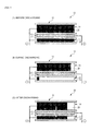
- FIGS. 6A to 6C are imaginary views showing the energy transfer condition between the negative electrodes during the charging
- FIGS. 7A to 7C are imaginary views showing the energy transfer condition between the negative electrodes during the discharging.
- the change in the potential is illustrated in the lateral direction, while the energy amount is illustrated with the colored area.
- high-current charging can be performed by utilizing the high output characteristic of the negative-electrode mixture layer 22, and further, the energy in the negative-electrode mixture layer 22 can move to the negative-electrode mixture layer 20, with the result that the potential of the negative-electrode mixture layer 22, which is temporarily reduced, can be recovered.
- the metal lithium is prevented from being deposited on the hard carbon, on which the metal lithium is easy to be deposited, and the high output and high capacity of the electric storage device 10 can be achieved. Specifically, even if a high-current charging is performed, no excessive load is applied on the negative-electrode mixture layer 20, and the deposition of the metal lithium can be prevented.
- the energy of the negative-electrode mixture layer 20 is transferred to the negative-electrode mixture layer 22 until the potentials of the negative-electrode mixture layer 20 and the negative-electrode mixture layer 22 reach an equilibrium potential.
- the high-current discharging can be performed by utilizing the high output characteristic of the negative-electrode mixture layer 22, and the energy from the negative-electrode mixture layer 20 can be supplied to the negative-electrode mixture layer 22 so that the potential of the negative-electrode mixture layer 22, which temporarily rises, can be recovered. Accordingly, the high output and the high capacity of the electric storage device 10 can be achieved.
- the electric storage device 10 includes the negative-electrode mixture layer 20 and the negative-electrode mixture layer 22, each having a different charge/discharge characteristic, i.e., each being of different types, wherein the negative-electrode mixture layer 20 and the negative-electrode mixture layer 22 are connected to each other, and the through-holes 16a are formed in the positive-electrode current collector 16 arranged between the negative-electrode mixture layer 20 and the negative-electrode mixture layer 22.
- the lithium ions can move between the negative-electrode mixture layer 20 and the negative-electrode mixture layer 22, whereby the difference in the potential between the negative-electrode mixture layer 20 and the negative-electrode mixture layer 22 can be canceled.
- the charge/discharge characteristic of the negative-electrode mixture layer 20 and the charge/discharge characteristic of the negative-electrode mixture layer 22 can be combined to be utilized without applying a great load on the negative-electrode mixture layer 20 and the negative-electrode mixture layer 22. Consequently, the output density and the energy density of the electric storage device 10 can be enhanced, while ensuring the durability of the electric storage device 10.
- the negative-electrode mixture layer 20 and the negative-electrode mixture layer 22 of different types are not in direct contact with each other. Therefore, even when one of the negative-electrode active materials is deteriorated, this deterioration does not affect the other negative-electrode active material, with the result that the durability of the electric storage device 10 can be enhanced.
- FIG. 8 is a sectional view schematically showing an internal structure of an electric storage device 30 according to another embodiment of the present invention.
- the same components as those shown in FIG. 1 are identified by the same numerals, and the explanation thereof is omitted.
- an electrode laminate unit 31 is arranged at the inside of the laminate film 11 constituting an outer casing of the electric storage device 30.
- This electrode laminate unit 31 includes a positive electrode system having two positive electrodes 32 and 33 and a negative electrode system having a single negative electrode 34.
- the negative electrode 34 arranged at the center of the electrode laminate unit 31 has a negative-electrode current collector (current collector) 35 provided with a large number of through-holes 35a, the first negative-electrode mixture layer 20 mounted on one surface of the negative-electrode current collector 35 and the second negative-electrode mixture layer 22 mounted on the other surface of the negative-electrode current collector 35.
- current collector current collector
- a first positive electrode 32 and a second positive electrode 33 are arranged with the separators 18 therebetween so as to sandwich the negative electrode 34.
- Each of the positive electrodes 32 and 33 includes a positive-electrode current collector (current collector) 36 and the positive-electrode mixture layer 17.
- the positive-electrode mixture layer 17 contains active carbon as a positive-electrode active material
- the negative-electrode mixture layer 20 contains hard carbon as a negative-electrode active material
- the negative-electrode mixture layers 22 contain PAS as a negative-electrode active material.
- the negative electrode terminal 24 is connected to the negative-electrode current collector 35 that connects the negative-electrode mixture layer 20 and the negative-electrode mixture layer 22, while the positive electrode terminal 23 is connected to the pair of the positive-electrode current collectors 36 that are connected to each other.
- an electric storage component including the positive-electrode mixture layer 17 and the negative-electrode mixture layer 20 opposite to the positive-electrode mixture layer 17 and an electric storage component including the positive-electrode mixture layer 17 and the negative-electrode mixture layer 22 opposite to the positive-electrode mixture layer 17 are connected in parallel.
- the negative-electrode mixture layer 20 and the negative-electrode mixture layer 22 of different types are electrically connected, and a great number of the through-holes 35a are formed in the negative-electrode current collector 35 arranged between the negative-electrode mixture layer 20 and the negative-electrode mixture layer 22, whereby the lithium ions can move between the negative-electrode mixture layer 20 and the negative-electrode mixture layer 22, like the electric storage device 10.
- the output density and the energy density of the electric storage device 30 can be enhanced, while ensuring the durability of the electric storage device 30.
- the negative-electrode mixture layer 20 and the negative-electrode mixture layer 22 are arranged to be adjacent to each other with the negative-electrode current collector 35 interposed therebetween. Therefore, the lithium ions can move quickly between the negative-electrode mixture layer 20 and the negative-electrode mixture layer 22.
- FIG. 9 is a sectional view schematically showing an internal structure of an electric storage device 40 of a laminate type according to another embodiment of the present invention.
- the same components as those shown in FIG. 1 and FIG. 8 are identified by the same numerals, and the explanation thereof is omitted.
- an electrode laminate unit 42 is arranged at the inside of a laminate film 41 constituting an outer casing of the electric storage device 40.
- This electrode laminate unit 42 includes a positive electrode system having six positive electrodes 43 and a negative electrode system having negative electrodes 44 to 46 the number of which is seven in total.
- the positive electrode system has positive electrodes 43 each including the positive-electrode current collector 16 provided with a large number of the through-holes 16a, and the positive-electrode mixture layers 17 mounted on both surfaces of the positive-electrode current collector 16.
- the negative electrode system has first negative electrodes 44 and 45 including the negative-electrode current collector 35 provided with a large number of the through-holes 35a, and the negative-electrode mixture layers 20 mounted on both surfaces or one surface of the negative-electrode current collector 35, and second negative electrodes 46 each including the negative-electrode current collector 35 provided with a large number of the through-holes 35a, and the negative-electrode mixture layers 22 mounted on both surfaces of the negative-electrode current collector 35.
- These positive electrodes 43 and the negative electrodes 44 to 46 are alternately laminated with the separators 18 arranged therebetween.
- the electric storage device 40 has a device structure of a laminated type.
- the positive-electrode mixture layers 17 contain active carbon as a positive-electrode active material
- the negative-electrode mixture layers 20 contain hard carbon as a negative-electrode active material
- the negative-electrode mixture layers 22 contain PAS as a negative-electrode active material.
- the positive electrode terminal 23 is connected to the plurality of positive-electrode current collectors 16 that are connected to each other, while the negative electrode terminal 24 is connected to the plurality of negative-electrode current collectors 35 that are connected to each other.
- a lithium ion source 47 is provided at the outermost part of the electrode laminate unit 42 so as to be opposite to the negative electrode 46.
- the lithium ion source 47 includes a lithium-electrode current collector 47a made of a conductive porous body such as a stainless mesh, and metal lithium 47b adhered onto the lithium-electrode current collector 47a.
- the negative-electrode current collector 35 and the lithium-electrode current collector 47a are short-circuited via a lead wire 48, whereby lithium ions are eluted from the metal lithium 47b and can be doped into the negative-electrode mixture layers 20 and 22 by injecting an electrolyte into the laminate film 11.
- the potential of the negative electrode can be reduced to thereby increase the capacity of the electric storage device 40.
- a large number of the through-holes 16a and 35a are formed in the positive-electrode current collector 16 and the negative-electrode current collector 35.
- the lithium ions can freely move between the electrodes via the through-holes 16a and 35a, whereby the lithium ions can be doped all over the all the laminated negative-electrode mixture layers 20 and 22.
- an alloy that can supply lithium ions such as a lithium - aluminum alloy, may be used. Further, the lithium ion source 47 and the positive electrodes 43 may be short-circuited so as to dope the lithium ions into the positive electrodes 43.
- the negative-electrode mixture layer 20 and the negative-electrode mixture layer 22 of different types are electrically connected, and a great number of the through-holes 16a and 35a are formed in the positive-electrode current collector 16 and the negative-electrode current collector 35 arranged between the negative-electrode mixture layer 20 and the negative-electrode mixture layer 22, whereby the lithium ions can move between the negative-electrode mixture layer 20 and the negative-electrode mixture layer 22, like the electric storage device 10.
- the output density and the energy density of the electric storage device 40 can be enhanced, while ensuring the durability of the electric storage device 40.
- the device structure of the laminated type is employed, so that the electrodes of several types can easily be combined, which makes the structure of the electric storage device 40 simple.
- the negative electrode system is composed by alternately laminating the negative electrodes 44 and 45 containing the hard carbon and the negative electrodes 46 containing PAS.
- the negative electrode system may be composed of the laminates of each of the negative electrodes 44 to 46.
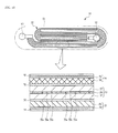
- FIG. 10 is a sectional view schematically showing an internal structure of an electric storage device 50 of a wound type according to another embodiment of the present invention.
- an electrode wound unit 52 is arranged at the inside of a metal can 51 constituting an outer casing of the electric storage device 50.
- This electrode wound unit 52 includes a positive electrode system having one positive electrode 53 and a negative electrode system having two negative electrodes 54 and 55.
- the positive electrode 53 mounted at the center of the electrode wound unit 52 includes a positive-electrode current collector (current collector) 56 provided with a large number of through-holes 56a, and positive-electrode mixture layers 57 mounted on both surfaces of the positive-electrode current collector 56.
- the first negative electrode 54 and the second negative electrode 55 are arranged with a separator 58 interposed therebetween so as to sandwich the positive electrode 53.
- the first negative electrode 54 has a negative-electrode current collector (current collector) 59 and a first negative-electrode mixture layer 60 applied on the negative-electrode current collector 59
- the second negative electrode 55 has a negative-electrode current collector 59 and a second negative-electrode mixture layer 61 applied on the negative-electrode current collector 59.
- the positive-electrode mixture layer 57 contains active carbon as a positive-electrode active material
- the negative-electrode mixture layer 60 contains hard carbon as a negative-electrode active material
- the negative-electrode mixture layer 61 contains PAS as a negative-electrode active material.
- a positive electrode terminal 62 is connected to the positive-electrode current collector 56, while a negative electrode terminal 63 is connected to the pair of the negative-electrode current collectors 59 that connect the negative-electrode mixture layers 60 and 61 to each other.
- the separator 58 adjacent to the negative-electrode current collector 59 may be omitted.
- the negative-electrode mixture layer 60 and the negative-electrode mixture layer 61 of different types are electrically connected, and a great number of the through-holes 56a are formed in the positive-electrode current collector 56 arranged between the negative-electrode mixture layer 60 and the negative-electrode mixture layer 61, whereby the lithium ions can move between the negative-electrode mixture layer 60 and the negative-electrode mixture layer 61, like the electric storage device 10.
- the output density and the energy density of the electric storage device 60 can be enhanced, while ensuring the durability of the electric storage device 60. Further, the device structure of the wound type is employed, with the result that the assembling process is simplified, so that the electric storage device 50 can be manufactured with low cost.
- A negative electrode
- B positive electrode
- C negative-electrode current collector and positive-electrode current collector
- D separator
- E electrolyte
- F outer casing.
- the negative electrode has a negative-electrode current collector and a negative-electrode mixture layer coated on the negative-electrode current collector, wherein a negative-electrode active material is contained in the negative-electrode mixture layer.
- the negative-electrode active material is not particularly limited, so long as it allows ions to be reversibly doped thereinto and de-doped therefrom.
- Examples of the negative-electrode active material include a graphite, various carbon materials, a polyacene-based material, tin oxide, silicon oxide.
- various carbon materials, a polyacene-based material, tin oxide, silicon oxide, etc., the first negative-electrode mixture layer and the second negative-electrode mixture layer, each having different charge/discharge characteristic can be formed.
- Graphite and hard carbon are preferable as the negative-electrode active material from the viewpoint of increasing the capacity of the electric storage device.
- a polyacene-based organic semiconductor (PAS) that is a heat-treated material of an aromatic condensation polymer and has a polyacene skeletal structure, in which a ratio of a number of hydrogen atoms H to a number of carbon atoms C is 0.05 or more and 0.50 or less is preferable for the negative-electrode active material, since it can increase the capacity. It is preferable that the H/C value of the PAS is within a range of not less than 0.05 and not more than 0.50.
- the H/C value of the PAS exceeds 0.50, the aromatic polycyclic structure is not sufficiently grown, so that the lithium ions cannot smoothly be doped or de-doped. Therefore, the charge/discharge efficiency of the electric storage device might be reduced.
- the H/C value of the PAS is less than 0.05, the capacity of the electric storage device can be decreased.
- the negative-electrode active material such as hard carbon and PAS is formed into a powdery shape, a granular shape or a short fibrous shape.
- This negative-electrode active material is mixed with a binder to form a slurry.
- the slurry containing the negative-electrode active material is coated on the negative-electrode current collector and the resultant is dried, whereby the negative-electrode mixture layer is formed on the negative-electrode current collector.
- Usable binders mixed with the negative-electrode active material include a fluorine-containing resin such as polytetrafluoroethylene, polyvinylidene fluoride, etc., a thermoplastic resin such as polypropylene, polyethylene, polyacrylate, etc, or a rubber-based binder such as styrene butadiene rubber (SBR).
- a fluorine-containing resin such as polytetrafluoroethylene, polyvinylidene fluoride, etc.
- a thermoplastic resin such as polypropylene, polyethylene, polyacrylate, etc
- a rubber-based binder such as styrene butadiene rubber (SBR).
- the fluorine-based binder is preferably used.
- the fluorine-based binder include polyvinylidene fluoride, copolymer of vinylidene fluoride and trifluoroethylene, copolymer of ethylene and tetrafluoroethylene, copolymer of propylene and tetrafluoroethylene, etc.
- a conductive material such as acetylene black, graphite, a metal powder, etc. may appropriately be added to the negative-electrode mixture layer.
- a dispersant or a thickener may be added as needed, and for example, carboxymethyl cellulose may be added.
- the positive electrode has a positive-electrode current collector and a positive-electrode mixture layer coated on the positive-electrode current collector.
- the positive-electrode mixture layer contains the positive-electrode active material.
- the positive-electrode active material is not particularly limited, so long as it allows ions to be reversibly doped thereinto and de-doped therefrom. Examples of the positive-electrode active materials include active carbon, transition metal oxides, conductive polymers, polyacene-based materials.
- the active carbon contained in the positive-electrode mixture layer as the positive-electrode active material is made of active carbon grains that are subject to an alkali activation treatment and have a specific surface area of not less than 600 m 2 /g.
- a phenolic resin, a petroleum pitch, a petroleum coke, a coconut husk, a coal-derived coke, etc. are used as the material of the active carbon, wherein it is preferable to use a phenolic resin or coal-derived coke, since they can increase the specific surface area.
- Preferable alkali activators used for the alkali activation treatment of the active carbons include salts or hydroxides of a metal ion such as lithium, sodium, potassium, etc., wherein potassium hydroxide is more preferable.
- Examples of the methods of the alkali activation include a method in which a carbide and an activator are mixed, and then, the resultant is heated in an airflow of an inert gas, the method in which an activator is carried on a raw material of an active carbon beforehand, the resultant is heated, and then, a carbonizing process and activating process are performed, a method in which a carbide is activated with a gas activation by using, for example, water vapors, and then, the resultant is surface-treated with an alkali activator.
- the active carbon to which the alkali activation treatment is performed is pulverized by means of a known pulverizer such as a ball mill or the like.
- the grain size generally used within a wide range can be applied.
- D 50 is 2 ⁇ m or more, more preferably 2 ⁇ m to 50 ⁇ m, and most preferably 2 ⁇ m to 20 ⁇ m.
- the active carbon preferably having an average pore diameter of 10 nm or less and a specific surface area of 600 to 3000 m 2 /g is preferable. More preferably, an active carbon having a specific surface area of 800 m 2 /g or more, particularly 1300 to 2500 m 2 /g is preferable.
- Lithium cobalt oxide may be contained in the positive-electrode mixture layer as the positive-electrode active material.
- the other materials include lithium-containing metal oxides represented by a chemical formula of Li x M y O z (wherein x, y, z are positive numbers, M is a metal, or may be metals of two or more types) such as, Li x CoO 2 , Li x NiO 2 , Li x MnO 2 , Li x FeO 2 , transition metal oxides such as a cobalt oxide, a manganese oxide, a vanadium oxide, a titanium oxide, or a nickel oxide, or a sulfide such as a cobalt sulfide, a manganese sulfide , a vanadium sulfide, a titanium sulfide, or a nickel sulfide.
- a lithium-containing oxide having a potential of 4 V or more with respect to metal lithium is preferably used. More preferable lithium-containing oxides include a lithium-containing cobalt oxide, a lithium-containing nickel oxide, or a lithium-containing cobalt-nickel compound oxide.
- the positive-electrode active material such as lithium cobalt oxide or the above described active carbon is formed into a powdery shape, a granular shape, a short fibrous shape, etc., and this positive-electrode active material is mixed with a binder to form a slurry.
- the slurry containing the positive-electrode active material is coated on the positive-electrode current collector and the resultant is dried, whereby the positive-electrode mixture layer is formed on the positive-electrode current collector.
- Usable binders mixed with the positive-electrode active material include a rubber binder such as SBR, a fluorine-containing resin such as polytetrafluoroethylene, polyvinylidene fluoride, a thermoplastic resin such as polypropylene, polyethylene, polyacrylate.
- a conductive material such as acetylene black, graphite, metal powder, etc. may appropriately be added to the positive-electrode mixture layer.
- a dispersant or a thickener may be added as needed, and for example carboxymethyl cellulose may be added
- the negative-electrode current collector and the positive-electrode current collector preferably have through holes penetrating therethrough.
- Examples thereof include an expanded metal, a punched metal, a net, an expanded member.
- the shape and number of the through hole are not particularly limited, and they are appropriately set so long as they do not hinder the movement of the anions and/or lithium ions.
- the negative-electrode current collectors 19 and 21 are not arranged between the negative-electrode mixture layer 20 and the negative-electrode mixture layer 22, so that the electric storage device 10 can be used without forming through-holes in the negative-electrode current collectors 19 and 21.
- the positive-electrode current collector 36 is not arranged between the negative-electrode mixture layer 20 and the negative-electrode mixture layer 22, so that the electric storage device 30 can be used without forming through-holes in the positive-electrode current collector 36.
- a porous member or the like having the durability with respect to the electrolyte, positive-electrode active material, negative-electrode active material, or the like, having an through hole and having no electron conductivity can be used for the separator.
- a cloth, a nonwoven fabric, or a porous body made of a paper (cellulose), a glass fiber, a polyethylene, a polypropylene, etc. is used.
- the thickness of the separator is preferably thin in order to reduce the internal resistance of the battery, but it may appropriately be set considering the holding amount of the electrolyte, strength of the separator, or the like.
- an aprotic organic solvent containing a lithium salt is used for the electrolyte from the viewpoint that an electrolysis is not produced even by a high voltage and lithium ions can stably be present.
- the aprotic organic solvent include ethylene carbonate, propylene carbonate, dimethyl carbonate, diethyl carbonate, ⁇ -butyloractone, acetonitrile, dimethoxyethane, tetrahydrofuran, dioxolane, methylene chloride, sulfolane, wherein these material are used singly or mixed with one another.
- the lithium salt examples include LiClO 4 , LiAsF 6 , LiBF 4 , LiPF 6 , LIN(C 2 F 5 SO 2 ) 2 .
- the concentration of the electrolyte in the electrolyte solution is preferably set to at least 0.1 mol/l or more, and more preferably set within a range of 0.5 to 1.5 mol/l, in order to reduce the internal resistance due to the electrolyte solution.
- outer casing Various materials generally used for a battery can be used for the outer casing.
- a metal material such as iron or aluminum may be used, and a film material or the like may be used.
- the shape of the outer casing is not particularly limited.
- the outer casing may be formed into a shape appropriately selected according to the purpose, such as a cylindrical shape or a rectangular shape.
- a film-type outer casing employing an aluminum laminate film.
- a three-layered laminate film having a nylon film at the outer part, an aluminum foil at the middle part, and an adhesive layer such as a denatured polypropylene at the inner part is used.
- a furfuryl alcohol which was a raw material of a furan resin, was retained at 60 °C for 24 hours so as to cure the furfuryl alcohol, to thereby obtain a black resin.
- the obtained black resin was put into a stationary electric furnace, and heat-treated for 3 hours under a nitrogen atmosphere till the temperature reached 1200 °C.
- the black resin was retained at 1200 °C for 2 hours.
- a slurry 1 for a negative electrode 86 parts by weight of the Sample 1, 6 parts by weight of acetylene black powder, 5 parts by weight of acrylic resin binder, 3 parts by weight of carboxylmethyl cellulose, and 200 parts by weight of water were fully mixed to obtain a slurry 1 for a negative electrode.
- the slurry 1 for a negative electrode was uniformly applied onto both surfaces of an expanded metal made of copper in a thickness of 32 ⁇ m (a porosity of 50%) by means of a die coater, and dried and pressed, whereby a negative electrode 1 with a thickness of 70 ⁇ m was produced.
- a phenolic resin molding plate with a thickness of 0.5 mm was put into a Siliconit electric furnace and heat-treated under a nitrogen atmosphere at a rate of 50 °C/hour till the temperature reached 500 °C, and further heat-treated at a rate of 10 °C/hour till the temperature reached 700 °C, whereby a PAS plate was synthesized.
- the PAS plate thus obtained was pulverized with a disc mill to obtain PAS powders.
- the PAS powders had a H/C ratio of 0.17.
- a slurry 2 for a negative electrode 86 parts by weight of the above PAS powder, 6 parts by weight of acetylene black powder, 5 parts by weight of acrylic resin binder, 3 parts by weight of carboxylmethyl cellulose, and 200 parts by weight of water were fully mixed to obtain a slurry 2 for a negative electrode.
- the slurry 2 for a negative electrode was coated uniformly over both surfaces of a copper expanded metal having a thickness of 32 ⁇ m (a porosity of 50%) by a die coater, and dried and pressed, whereby a negative electrode 2 with a thickness of 86 ⁇ m was produced.
- Both surfaces of an aluminum expanded metal having a thickness of 35 ⁇ m (a porosity of 50%) was coated with a non-aqueous carbon conductive coating by a spraying method, and dried thereby to obtain a positive-electrode current collector having a conductive layer thereon.
- the total thickness (the sum of the current collector thickness and the conductive layer thickness) of the positive-electrode current collector was 52 ⁇ m, and most of the through-holes of the positive-electrode current collector were filled with the conductive coating.
- the slurry for the positive electrode was uniformly applied over both surfaces of the positive-electrode current collector by means of a roll coater, and dried and pressed to produce a positive electrode 1 having a thickness of 129 ⁇ m.
- the thickness of the positive-electrode mixture layer formed on the positive electrode 1 was 77 ⁇ m, and the area density of the positive-electrode active material was 3.5 mg/cm 2 .
- the negative electrode 1 was cut out into six pieces, each having an area of 6.0 cm x 7.5 cm (excluding the terminal welding parts), the negative electrode 2 was cut out into six pieces, each having an area of 6.0 cm x 7.5 cm (excluding the terminal welding parts), and the positive electrode 1 was cut out into eleven pieces, each having an area of 5.8 cm x 7.3 cm (excluding the terminal welding parts).
- the negative electrodes 2 and the positive electrode 1 were alternately laminated through a separator of a nonwoven fabric made of cellulose/rayon with a thickness of 35 ⁇ m in a manner that the terminal welding parts of the positive-electrode current collectors and that of the negative-electrode current collectors were set in the opposite side.
- the negative electrodes were the outermost electrodes of the electrode laminate unit 1. Then, separators were arranged at the uppermost part and the lowermost part of the electrode laminate unit 1, and the four sides of the electrode laminate unit 1 were fastened with a tape.
- the terminal welding parts (eleven sheets) of the positive-electrode current collectors were ultrasonically welded to an aluminum positive electrode terminal (having a width of 50 mm, a length of 50 mm, a thickness of 0.2 mm), and the terminal welding parts (twelve sheets) of the negative-electrode current collectors were ultrasonically welded to a copper negative electrode terminal (having a width of 50 mm, a length of 50 mm, a thickness of 0.2 mm), thereby to obtain an electrode laminate unit 1.
- a lithium electrode was formed by pressing a metal lithium foil onto a stainless steel mesh with a thickness of 80 ⁇ m.
- the lithium electrode was located on the upper part of the electrode laminate unit 1 such that it exactly faces the negative electrode at the outermost part.
- the terminal welding part of the lithium-electrode current collector was resistance-welded to the negative electrode terminal welding parts.
- the three-electrode laminate unit was placed in a laminate film deep-drawn to 3.5 mm, and the opening portion was covered with other laminate film and three sides were heat-sealed. Then, the unit was vacuum-impregnated with an electrolyte solution (a solution formed by dissolving LiPF 6 at 1 mol/L into propylene carbonate). Then, the remaining one side of the unit was heat-sealed.
- an electrolyte solution a solution formed by dissolving LiPF 6 at 1 mol/L into propylene carbonate.
- each cell 1 having the negative electrode 1 in which the negative-electrode mixture layer contained the hard carbon, and the negative electrode 2 in which the negative-electrode mixture layer contained the PAS were assembled, wherein the current collectors (expanded metal) provided with through-holes were arranged between the negative-electrode mixture layers of the negative electrode 1 and the negative electrode 2.
- the metal lithium located in each cell 1 was equivalent to 550 mAh/g per negative-electrode active material weight.
- the thus assembled cells 1 were left to stand for 20 days, and one cell of four cells was disassembled. It was confirmed that no metal lithium remained. From this fact, it was considered that the amount of lithium ion equivalent to 550 mAh/g per negative-electrode active material weight was pre-doped.
- the cell 1 was charged for thirty minutes by a constant current-constant voltage charging method in which the cell was charged at a constant current of 5000 mA till the cell voltage reached 3.8 V and then charged at a constant voltage of 3.8 V. Then, the cell was discharged at a constant current of 500 mA till the cell voltage reached 2.2 V.
- the cell was left for two hours in a thermostatic chamber at -20 °C, and then, the cycle of the charging operation to 3.8 V and the discharging operation to 2.2 V was repeated, and when the cycle was repeated 1000 times, the capacity of the cell was evaluated after the cell was returned to a room temperature.
- the negative electrode 1 was cut out into twelve pieces, each having an area of 6.0 cm x 7.5 cm (excluding the terminal welding parts), and the positive electrode 1 was cut out into eleven pieces, each having an area of 5.8 cm x 7.3 cm (excluding the terminal welding parts).
- the electrode laminate unit 2 was fabricated in the same manner as in the Example 1, except that only the negative electrode 1 containing hard carbon in the negative-electrode mixture layer was used as the negative electrode. Fabrication of cell 2
- the cell 2 was charged for thirty minutes by a constant current-constant voltage charging method in which the cell was charged at a constant current of 5000 mA till the cell voltage reached 3.8 V and then charged at a constant voltage of 3.8 V. Then, the cell was discharged at a constant current of 500 mA till the cell voltage reached 2.2 V. The cycle of the charging operation to 3.8 V and the discharging operation to 2.2 V was repeated, and when the cycle was repeated 10 times, the capacity and the energy density of the cell were evaluated.
- the negative electrode 2 was cut out into twelve pieces, each having an area of 6.0 cm x 7.5 cm (excluding the terminal welding parts), and the positive electrode 1 was cut out into eleven pieces, each having an area of 5.8 cm x 7.3 cm (excluding the terminal welding parts).
- the electrode laminate unit 3 was fabricated in the same manner as in the Example 1, except that only the negative electrode 2 containing the PAS in the negative-electrode mixture layer was used as the negative electrode. Fabrication of cell 3
- the cell 3 was charged for thirty minutes by a constant current-constant voltage charging method in which the cell was charged at a constant current of 5000 mA till the cell voltage reached 3.8 V and then charged at a constant voltage of 3.8 V. Then, the cell was discharged at a constant current of 500 mA till the cell voltage reached 2.2 V.
- the cell 3 was left for two hours in a thermostatic chamber at -20 °C, and then, the cycle of the charging operation to 3.8 V and the discharging operation to 2.2 V was repeated, and when the cycle was repeated 1000 times, the capacity of the cell was evaluated after the cell was returned to a room temperature.
- the cell 1 according to the Example 1 includes the negative electrode 1 having the hard carbon, which has a great capacity, and the negative electrode 2 having the PAS, which has a low resistance. Therefore, it was confirmed from Table 1 that the cell 1 according to the Example 1 had a high energy density and a high capacity retention ratio.
- the cell 2 according to the Comparative Example 1 employs only the negative electrode 1 having the hard carbon, which has a great capacity, as a negative electrode. Therefore, it was confirmed from Table 2 that the cell 2 had a high energy density, but the capacity retention ratio was low due to the deposition of the metal lithium described below.
- the cell 3 according to the Comparative Example 2 employs only the negative electrode 2 having the PAS, which has a low resistance, as a negative electrode. Therefore, it was confirmed from Table 3 that the cell 3 had a high capacity retention ratio, but the energy density was low due to the capacity and the electrode density of the PAS that were lower than those of the hard carbon.
- the deposition of the metal lithium was recognized on the negative electrode 1 containing the hard carbon of the cell 2 according to the Comparative Example 1.
- the deposition of the metal lithium is caused by the fact that the resistance of the hard carbon is higher than that of the PAS and the allowable storage quantity of the lithium ions of the hard carbon is lower than that of the PAS.
- the slurry 1 for a negative electrode used in the Example 1 was applied over one surface of the negative-electrode current collector by means of a roll coater, dried, and pressed to produce a negative electrode with a thickness of 43 ⁇ m. Then, the slurry 2 for a negative electrode used in the Example 1 was applied over the other surface of the negative-electrode current collector by means of a roll coater, dried and pressed to produce a negative electrode 3 with a thickness of 78 ⁇ m.
- the negative-electrode mixture layer containing hard carbon was formed on one surface of the negative-electrode current collector, while the negative-electrode mixture layer containing PAS was formed on the other surface of the negative-electrode current collector.
- the area density of the negative-electrode active material was 2.0 mg/cm 2 on both surfaces.
- the negative electrode 3 was cut out into twelve pieces, each having an area of 6.0 cm x 7.5 cm (excluding the terminal welding parts), and the positive electrode 1 was cut out into eleven pieces, each having an area of 5.8 cm x 7.3 cm (excluding the terminal welding parts).
- the electrode laminate unit 4 was fabricated in the same manner as in the Example 1, except that only the negative electrode 3 having the negative-electrode mixture layer containing the hard carbon and the negative-electrode mixture layer containing the PAS was used as the negative electrode. Fabrication of cell 4
- the cell 4 was charged for thirty minutes by a constant current-constant voltage charging method in which the cell was charged at a constant current of 5000 mA till the cell voltage reached 3.8 V and then charged at a constant voltage of 3.8 V.
- the cell was discharged at a constant current of 500 mA till the cell voltage reached 2.2 V.
- the cycle of the charging operation to 3.8 V and the discharging operation to 2.2 V was repeated, and when the cycle was repeated 10 times, the capacity and the energy density of the cell were evaluated.
- the cell 4 according to the Example 2 had a high energy density and a high capacity retention ratio, since it had the negative electrode 3 including the negative-electrode mixture layer containing hard carbon with a high capacity at one surface and the negative-electrode mixture layer containing PAS with a low resistance on the other surface.
- the load on the negative-electrode mixture layer containing hard carbon is reduced, so that the metal lithium is not deposited.
- the capacity retention ratio becomes higher than that in the Example 1. It is estimated that it is because the moving speed of the lithium ions is faster than that in the Example 1, since the negative-electrode mixture layer of two different types are applied on both surfaces of the current collector.
- the negative electrode 1 was cut out into six pieces, each having an area of 6.0 cm x 7.5 cm (excluding the terminal welding parts), the negative electrode 2 was cut out into six pieces, each having an area of 6.0 cm x 7.5 cm (excluding the terminal welding parts), and the positive electrode 2 was cut out into eleven pieces, each having an area of 5.8 cm x 7.3 cm (excluding the terminal welding parts).
- the negative electrodes 2, and the positive electrode 2 were alternately laminated through a separator of a nonwoven fabric made of cellulose/rayon with a thickness of 35 ⁇ m in a manner that the terminal welding parts of the positive-electrode current collectors and the negative-electrode current collectors were set in the opposite side.
- the negative electrodes were the outermost electrodes of the electrode laminate unit 5. Then, separators were arranged at the uppermost part and the lowermost part, and the four sides of the structure were fastened with a tape.
- the terminal welding parts (eleven sheets) of the positive-electrode current collectors were ultrasonically welded to an aluminum positive electrode terminal (having a width of 50 mm, a length of 50 mm, a thickness of 0.2 mm), and the terminal welding parts (twelve sheets) of the negative-electrode current collectors were ultrasonically welded to a copper negative electrode terminal (having a width of 50 mm, a length of 50 mm, a thickness of 0.2 mm), thereby to obtain an electrode laminate unit 5. Fabrication of cell 5
- the cell 5 was charged for twelve hours by a constant current-constant voltage charging method in which the cell was charged at a constant current of 500 mA till the cell voltage reached 4.2 V and then charged at a constant voltage of 4.2 V. Then, the cell was discharged at a constant current of 50 mA till the cell voltage reached 3.0 V. The cycle of the charging operation to 4.2 V and the discharging operation to 3.0 V was repeated, and when the cycle was repeated 10 times, the capacity and the energy density of the cell were evaluated.
- the cell 6 was charged for twelve hours by a constant current-constant voltage charging method in which the cell was charged at a constant current of 500 mA till the cell voltage reached 4.2 V and then charged at a constant voltage of 4.2 V.
- the cell was discharged at a constant current of 50 mA till the cell voltage reached 3.0 V.
- the cycle of the charging operation to 4.2 V and the discharging operation to 3.0 V was repeated, and when the cycle was repeated 10 times, the capacity and the energy density of the cell were evaluated.
- the cell 5 according to the Example 3 includes the negative electrode 1 having hard carbon, which has a great capacity, and the negative electrode 2 having PAS, which has a low resistance. Therefore, it was confirmed from Table 5 that the cell 5 according to the Example 3 had a high energy density and a high capacity retention ratio.
- the cell 6 according to the Comparative Example 3 employs only the negative electrode 1 having hard carbon, which has a great capacity, as a negative electrode. Therefore, it was confirmed from Table 6 that the cell 6 had a high energy density, but the capacity retention ratio was low due to the deposition of the metal lithium described below.
- the deposition of the metal lithium was recognized on the negative electrode 1 containing hard carbon of the cell 6 according to the Comparative Example 3.
- the deposition of the metal lithium is caused by the fact that the resistance of hard carbon is higher than that of PAS and the allowable storage quantity of the lithium ions of hard carbon is lower than that of PAS.
- the current collector in the Comparative Example 3 is made of an aluminum foil and a copper foil having no through-holes, the lithium ions from the positive electrode, which is opposite to the hard carbon having a small allowable storage quantity of lithium ions, cannot be temporarily stored to the PAS through the through-holes, whereby the metal lithium is deposited.
- two negative-electrode mixture layers of different types (characteristics) 20 and 22, 60 and 61 are connected to each other, and the through-holes 16a, 35a, and 56a are formed on the positive-electrode current collectors 16 and 56 or the negative-electrode current collector 35 arranged between the negative-electrode mixture layers 20 and 22, 60 and 61.
- the invention is not limited thereto.
- Three or more negative-electrode mixture layers of different types can be connected to one another, and the through-holes may be formed on the negative-electrode current collector and the positive-electrode current collector arranged between these negative-electrode mixture layers.
- the positive-electrode active material and the negative-electrode active material are not limited to the active materials of the above embodiments.
- Various active materials used for a conventional battery or a capacitor are applicable.
- various electrolytes and separators used for a conventional battery or a capacitor can also be used for the electrolyte and the separator 18.
- the electric storage device is highly effective as a driving storage power source or an auxiliary storage power source for an electric vehicle, a hybrid vehicle, or the like. Further, the electric storage device according to the present invention is well adaptable to a driving storage power source for an electric bicycle, a motorized wheelchair, or the like, a storage power source used in a photovoltaic power generating device or a wind power generating device, or a storage power source used in a portable device or an electric appliance.
Landscapes
- Chemical & Material Sciences (AREA)
- Electrochemistry (AREA)
- Chemical Kinetics & Catalysis (AREA)
- General Chemical & Material Sciences (AREA)
- Engineering & Computer Science (AREA)
- Materials Engineering (AREA)
- Manufacturing & Machinery (AREA)
- Composite Materials (AREA)
- Power Engineering (AREA)
- Inorganic Chemistry (AREA)
- Microelectronics & Electronic Packaging (AREA)
- Battery Electrode And Active Subsutance (AREA)
- Secondary Cells (AREA)
- Cell Electrode Carriers And Collectors (AREA)
Applications Claiming Priority (1)
| Application Number | Priority Date | Filing Date | Title |
|---|---|---|---|
| JP2007240986A JP5214199B2 (ja) | 2007-09-18 | 2007-09-18 | 蓄電デバイス |
Publications (2)
| Publication Number | Publication Date |
|---|---|
| EP2040320A1 true EP2040320A1 (de) | 2009-03-25 |
| EP2040320B1 EP2040320B1 (de) | 2016-11-09 |
Family
ID=40139227
Family Applications (1)
| Application Number | Title | Priority Date | Filing Date |
|---|---|---|---|
| EP08164586.3A Active EP2040320B1 (de) | 2007-09-18 | 2008-09-18 | Elektrische Speichervorrichtung |
Country Status (5)
| Country | Link |
|---|---|
| US (1) | US8283072B2 (de) |
| EP (1) | EP2040320B1 (de) |
| JP (1) | JP5214199B2 (de) |
| KR (1) | KR101510886B1 (de) |
| CN (1) | CN101394002B (de) |
Cited By (7)
| Publication number | Priority date | Publication date | Assignee | Title |
|---|---|---|---|---|
| WO2011157618A1 (de) * | 2010-06-18 | 2011-12-22 | Continental Automotive Gmbh | Akkumulatorzelle und batterie |
| EP2579364A4 (de) * | 2010-05-31 | 2016-03-23 | Sumitomo Electric Industries | Dreidimensionales, netzartiges, poröses aluminiummaterial, elektrode aus dem porösen aluminiummaterial, mit der elektrode ausgestattete batterie mit nichtwässrigem elektrolyt sowie mit der elektrode ausgestatteter kondensator mit einer nichtwässrigen elektrolytlösung |
| US9660269B2 (en) | 2012-11-09 | 2017-05-23 | Sei Corporation | Electrode for lithium secondary battery and lithium secondary battery |
| EP3300146A1 (de) * | 2016-09-22 | 2018-03-28 | Industrial Technology Research Institute | Metall-ionen-sekundärbatterie |
| CN112271392A (zh) * | 2019-01-09 | 2021-01-26 | 比亚迪股份有限公司 | 动力电池包、储能装置以及电动车 |
| US10944281B2 (en) | 2012-12-26 | 2021-03-09 | Semiconductor Energy Laboratory Co., Ltd. | Power storage device and method for charging the same |
| FR3115162A1 (fr) * | 2020-10-08 | 2022-04-15 | Renault S.A.S. | Electrode pour cellule de batterie solide et procédé de fabrication d’une cellule de batterie utilisant une telle électrode. |
Families Citing this family (17)
| Publication number | Priority date | Publication date | Assignee | Title |
|---|---|---|---|---|
| JP4274256B2 (ja) * | 2006-08-25 | 2009-06-03 | トヨタ自動車株式会社 | 蓄電装置用電極及び蓄電装置 |
| KR101156538B1 (ko) * | 2010-05-14 | 2012-07-11 | 삼성에스디아이 주식회사 | 음극 활물질 및 이를 이용한 리튬 전지 |
| KR101153610B1 (ko) * | 2010-06-08 | 2012-06-11 | 삼성전기주식회사 | 2차 전원용 전극 및 이를 포함하는 2차 전원 |
| TW201236239A (en) * | 2010-11-16 | 2012-09-01 | Solvay | Rechargeable metal or metal-ion cell |
| JP5787185B2 (ja) * | 2011-02-04 | 2015-09-30 | トヨタ自動車株式会社 | 二次電池 |
| US10673069B2 (en) * | 2012-06-25 | 2020-06-02 | Battelle Memorial Institute | Hybrid anodes for energy storage devices |
| JP2014075191A (ja) * | 2012-10-02 | 2014-04-24 | Sharp Corp | 非水系二次電池用電極及び非水系二次電池 |
| JP6271010B2 (ja) * | 2013-12-03 | 2018-01-31 | エルジー・ケム・リミテッド | 出力及び容量特性が異なる電極を含んでいるハイブリッド型二次電池 |
| WO2016052934A1 (ko) * | 2014-09-29 | 2016-04-07 | 주식회사 엘지화학 | 애노드, 이를 포함하는 리튬 이차 전지, 상기 리튬 이차 전지를 포함하는 전지 모듈 및 애노드의 제조방법 |
| JP6776530B2 (ja) * | 2015-12-14 | 2020-10-28 | 株式会社村田製作所 | 電池、電池パック、電子機器、電動車両、蓄電装置および電力システム |
| HUE063923T2 (hu) | 2016-09-29 | 2024-02-28 | Lg Energy Solution Ltd | Természetes grafitot és mesterséges grafitot tartalmazó többrétegû negatív elektród és ilyen többrétegû negatív elektródot tartalmazó lítium másodlagos akkumulátor |
| CN107369812A (zh) * | 2017-09-14 | 2017-11-21 | 湖南格兰博智能科技有限责任公司 | 一种负极片和电容型锂离子电池 |
| KR102639173B1 (ko) * | 2019-04-26 | 2024-02-22 | 엘에스머트리얼즈 주식회사 | 에너지 저장장치 |
| CN112216876B (zh) * | 2019-07-10 | 2022-04-15 | 比亚迪股份有限公司 | 锂离子电池重复单元、锂离子电池及其使用方法、电池模组和汽车 |
| CN112216879B (zh) * | 2019-07-10 | 2022-05-13 | 比亚迪股份有限公司 | 锂离子电池重复单元、锂离子电池及其使用方法、电池模组和汽车 |
| KR102836397B1 (ko) | 2019-11-11 | 2025-07-18 | 주식회사 엘지에너지솔루션 | 평행하게 병렬 배치된 복수의 집전체를 포함하는 음극 및 이를 포함하는 이차전지 |
| EP4571926A4 (de) * | 2023-01-03 | 2025-11-26 | Contemporary Amperex Technology Hong Kong Ltd | Batteriezelle, laminierte batterie und elektrische vorrichtung |
Citations (9)
| Publication number | Priority date | Publication date | Assignee | Title |
|---|---|---|---|---|
| JP2000036325A (ja) | 1998-07-16 | 2000-02-02 | Asahi Glass Co Ltd | 二次電源 |
| JP2001351688A (ja) | 2000-06-07 | 2001-12-21 | Fdk Corp | 電池・キャパシタ複合素子 |
| WO2002041420A1 (fr) | 2000-11-17 | 2002-05-23 | Kansai Research Institute, Inc. | Cellule secondaire de lithium non aqueux |
| JP2005203131A (ja) | 2004-01-13 | 2005-07-28 | Hitachi Ltd | エネルギーデバイス |
| EP1612819A2 (de) * | 2003-03-31 | 2006-01-04 | Fuji Jukogyo Kabushiki Kaisha | Kondensator mit organischem elektrolyt |
| EP1734547A1 (de) * | 2004-03-31 | 2006-12-20 | Fuji Jukogyo Kabushiki Kaisha | Organischer elektrolytkondensator mit mesoporösem kohlenstoffmaterial als negativelektrode |
| US20070077494A1 (en) * | 2005-09-29 | 2007-04-05 | Sanyo Electric Co., Ltd. | Lithium secondary battery |
| JP2007141897A (ja) * | 2005-11-14 | 2007-06-07 | Fuji Heavy Ind Ltd | リチウムイオンキャパシタ |
| JP2007173615A (ja) * | 2005-12-22 | 2007-07-05 | Fuji Heavy Ind Ltd | 電池又はキャパシタ用リチウム金属箔 |
Family Cites Families (5)
| Publication number | Priority date | Publication date | Assignee | Title |
|---|---|---|---|---|
| DE69837838T2 (de) * | 1997-01-27 | 2008-01-31 | Fuji Jukogyo K.K. | Organische, elektrolytische batterie |
| JPH11135105A (ja) * | 1997-10-31 | 1999-05-21 | Toyota Central Res & Dev Lab Inc | 電 池 |
| JP4701579B2 (ja) * | 2002-01-23 | 2011-06-15 | 日本電気株式会社 | 二次電池用負極 |
| JP2004055425A (ja) * | 2002-07-23 | 2004-02-19 | Nissan Motor Co Ltd | 積層型二次電池および電池要素体 |
| JP4162510B2 (ja) * | 2003-02-28 | 2008-10-08 | 三洋電機株式会社 | 非水電解質二次電池 |
-
2007
- 2007-09-18 JP JP2007240986A patent/JP5214199B2/ja active Active
-
2008
- 2008-07-14 KR KR20080068222A patent/KR101510886B1/ko active Active
- 2008-09-09 US US12/206,843 patent/US8283072B2/en active Active
- 2008-09-18 EP EP08164586.3A patent/EP2040320B1/de active Active
- 2008-09-18 CN CN200810161204.8A patent/CN101394002B/zh active Active
Patent Citations (9)
| Publication number | Priority date | Publication date | Assignee | Title |
|---|---|---|---|---|
| JP2000036325A (ja) | 1998-07-16 | 2000-02-02 | Asahi Glass Co Ltd | 二次電源 |
| JP2001351688A (ja) | 2000-06-07 | 2001-12-21 | Fdk Corp | 電池・キャパシタ複合素子 |
| WO2002041420A1 (fr) | 2000-11-17 | 2002-05-23 | Kansai Research Institute, Inc. | Cellule secondaire de lithium non aqueux |
| EP1612819A2 (de) * | 2003-03-31 | 2006-01-04 | Fuji Jukogyo Kabushiki Kaisha | Kondensator mit organischem elektrolyt |
| JP2005203131A (ja) | 2004-01-13 | 2005-07-28 | Hitachi Ltd | エネルギーデバイス |
| EP1734547A1 (de) * | 2004-03-31 | 2006-12-20 | Fuji Jukogyo Kabushiki Kaisha | Organischer elektrolytkondensator mit mesoporösem kohlenstoffmaterial als negativelektrode |
| US20070077494A1 (en) * | 2005-09-29 | 2007-04-05 | Sanyo Electric Co., Ltd. | Lithium secondary battery |
| JP2007141897A (ja) * | 2005-11-14 | 2007-06-07 | Fuji Heavy Ind Ltd | リチウムイオンキャパシタ |
| JP2007173615A (ja) * | 2005-12-22 | 2007-07-05 | Fuji Heavy Ind Ltd | 電池又はキャパシタ用リチウム金属箔 |
Cited By (12)
| Publication number | Priority date | Publication date | Assignee | Title |
|---|---|---|---|---|
| EP2579364A4 (de) * | 2010-05-31 | 2016-03-23 | Sumitomo Electric Industries | Dreidimensionales, netzartiges, poröses aluminiummaterial, elektrode aus dem porösen aluminiummaterial, mit der elektrode ausgestattete batterie mit nichtwässrigem elektrolyt sowie mit der elektrode ausgestatteter kondensator mit einer nichtwässrigen elektrolytlösung |
| US9711801B2 (en) | 2010-05-31 | 2017-07-18 | Sumitomo Electric Industries, Ltd. | Three-dimensional net-like aluminum porous body, electrode using the aluminum porous body, nonaqueous electrolyte battery using the electrode, and nonaqueous electrolyte capacitor using the electrode |
| WO2011157618A1 (de) * | 2010-06-18 | 2011-12-22 | Continental Automotive Gmbh | Akkumulatorzelle und batterie |
| US8993140B2 (en) | 2010-06-18 | 2015-03-31 | Continental Automotive Gmbh | Rechargeable battery cell and battery |
| US9660269B2 (en) | 2012-11-09 | 2017-05-23 | Sei Corporation | Electrode for lithium secondary battery and lithium secondary battery |
| US10944281B2 (en) | 2012-12-26 | 2021-03-09 | Semiconductor Energy Laboratory Co., Ltd. | Power storage device and method for charging the same |
| US11777108B2 (en) | 2012-12-26 | 2023-10-03 | Semiconductor Energy Laboratory Co., Ltd. | Power storage device and method for charging the same |
| EP3300146A1 (de) * | 2016-09-22 | 2018-03-28 | Industrial Technology Research Institute | Metall-ionen-sekundärbatterie |
| US11101467B2 (en) | 2016-09-22 | 2021-08-24 | Industrial Technology Research Institute | Metal-ion secondary battery |
| CN112271392A (zh) * | 2019-01-09 | 2021-01-26 | 比亚迪股份有限公司 | 动力电池包、储能装置以及电动车 |
| CN112271392B (zh) * | 2019-01-09 | 2023-05-09 | 比亚迪股份有限公司 | 动力电池包、储能装置以及电动车 |
| FR3115162A1 (fr) * | 2020-10-08 | 2022-04-15 | Renault S.A.S. | Electrode pour cellule de batterie solide et procédé de fabrication d’une cellule de batterie utilisant une telle électrode. |
Also Published As
| Publication number | Publication date |
|---|---|
| CN101394002B (zh) | 2014-08-27 |
| KR101510886B1 (ko) | 2015-04-10 |
| CN101394002A (zh) | 2009-03-25 |
| JP5214199B2 (ja) | 2013-06-19 |
| US20090075161A1 (en) | 2009-03-19 |
| KR20090029624A (ko) | 2009-03-23 |
| JP2009070782A (ja) | 2009-04-02 |
| US8283072B2 (en) | 2012-10-09 |
| EP2040320B1 (de) | 2016-11-09 |
Similar Documents
| Publication | Publication Date | Title |
|---|---|---|
| US8283072B2 (en) | Electric storage device | |
| US9012089B2 (en) | Electric storage device | |
| EP2058893B1 (de) | Elektrische Speichervorrichtung | |
| EP2040321A1 (de) | Elektrische Speichervorrichtung | |
| EP2088637B1 (de) | Elektrische Speichervorrichtung | |
| US8148002B2 (en) | Electric storage device | |
| EP2228862B1 (de) | Gewickelte elektrische Speichervorrichtung mit einer zusätzlichen Ionenquelle | |
| EP2154741A1 (de) | Elektrische Speichervorrichtung | |
| EP2105985A1 (de) | Kohlenstoffmaterial für negative Elektrode, Elektrospeichervorrichtung und Produkt mit darauf montierter Elektrospeichervorrichtung | |
| US20130045427A1 (en) | Prelithiated current collector and secondary lithium cells containing same | |
| CN208400926U (zh) | 电极组件以及包括该电极组件的锂二次电池 | |
| KR20080081297A (ko) | 리튬이온 커패시터 | |
| KR20240058437A (ko) | 리튬 이차 전지 | |
| JP2009076763A (ja) | 蓄電デバイス |
Legal Events
| Date | Code | Title | Description |
|---|---|---|---|
| PUAI | Public reference made under article 153(3) epc to a published international application that has entered the european phase |
Free format text: ORIGINAL CODE: 0009012 |
|
| AK | Designated contracting states |
Kind code of ref document: A1 Designated state(s): AT BE BG CH CY CZ DE DK EE ES FI FR GB GR HR HU IE IS IT LI LT LU LV MC MT NL NO PL PT RO SE SI SK TR |
|
| AX | Request for extension of the european patent |
Extension state: AL BA MK RS |
|
| 17P | Request for examination filed |
Effective date: 20090924 |
|
| AKX | Designation fees paid |
Designated state(s): DE FR GB NL |
|
| RBV | Designated contracting states (corrected) |
Designated state(s): DE FR GB NL |
|
| 17Q | First examination report despatched |
Effective date: 20130301 |
|
| RAP1 | Party data changed (applicant data changed or rights of an application transferred) |
Owner name: FUJI JUKOGYO KABUSHIKI KAISHA |
|
| REG | Reference to a national code |
Ref country code: DE Ref legal event code: R079 Ref document number: 602008047251 Country of ref document: DE Free format text: PREVIOUS MAIN CLASS: H01M0004580000 Ipc: H01M0004660000 |
|
| GRAP | Despatch of communication of intention to grant a patent |
Free format text: ORIGINAL CODE: EPIDOSNIGR1 |
|
| RIC1 | Information provided on ipc code assigned before grant |
Ipc: H01M 4/74 20060101ALI20160401BHEP Ipc: H01M 4/66 20060101AFI20160401BHEP Ipc: H01M 4/70 20060101ALI20160401BHEP Ipc: H01M 4/36 20060101ALI20160401BHEP Ipc: H01M 10/058 20100101ALI20160401BHEP Ipc: H01M 10/04 20060101ALI20160401BHEP Ipc: H01M 4/587 20100101ALI20160401BHEP Ipc: H01M 4/80 20060101ALI20160401BHEP Ipc: H01M 10/0525 20100101ALI20160401BHEP Ipc: H01M 4/13 20100101ALI20160401BHEP Ipc: H01M 4/137 20100101ALI20160401BHEP |
|
| INTG | Intention to grant announced |
Effective date: 20160418 |
|
| GRAS | Grant fee paid |
Free format text: ORIGINAL CODE: EPIDOSNIGR3 |
|
| GRAA | (expected) grant |
Free format text: ORIGINAL CODE: 0009210 |
|
| AK | Designated contracting states |
Kind code of ref document: B1 Designated state(s): DE FR GB NL |
|
| REG | Reference to a national code |
Ref country code: GB Ref legal event code: FG4D |
|
| REG | Reference to a national code |
Ref country code: DE Ref legal event code: R096 Ref document number: 602008047251 Country of ref document: DE |
|
| REG | Reference to a national code |
Ref country code: NL Ref legal event code: MP Effective date: 20161109 |
|
| PG25 | Lapsed in a contracting state [announced via postgrant information from national office to epo] |
Ref country code: NL Free format text: LAPSE BECAUSE OF FAILURE TO SUBMIT A TRANSLATION OF THE DESCRIPTION OR TO PAY THE FEE WITHIN THE PRESCRIBED TIME-LIMIT Effective date: 20161109 |
|
| REG | Reference to a national code |
Ref country code: DE Ref legal event code: R082 Ref document number: 602008047251 Country of ref document: DE Representative=s name: MEISSNER BOLTE PATENTANWAELTE RECHTSANWAELTE P, DE Ref country code: DE Ref legal event code: R081 Ref document number: 602008047251 Country of ref document: DE Owner name: SUBARU CORPORATION, JP Free format text: FORMER OWNER: FUJI JUKOGYO KABUSHIKI KAISHA, TOKYO, JP |
|
| RAP2 | Party data changed (patent owner data changed or rights of a patent transferred) |
Owner name: SUBARU CORPORATION |
|
| REG | Reference to a national code |
Ref country code: DE Ref legal event code: R097 Ref document number: 602008047251 Country of ref document: DE |
|
| PLBE | No opposition filed within time limit |
Free format text: ORIGINAL CODE: 0009261 |
|
| STAA | Information on the status of an ep patent application or granted ep patent |
Free format text: STATUS: NO OPPOSITION FILED WITHIN TIME LIMIT |
|
| REG | Reference to a national code |
Ref country code: FR Ref legal event code: PLFP Year of fee payment: 10 |
|
| 26N | No opposition filed |
Effective date: 20170810 |
|
| REG | Reference to a national code |
Ref country code: FR Ref legal event code: CD Owner name: SUBARU CORPORATION, JP Effective date: 20171114 |
|
| GBPC | Gb: european patent ceased through non-payment of renewal fee |
Effective date: 20170918 |
|
| PG25 | Lapsed in a contracting state [announced via postgrant information from national office to epo] |
Ref country code: GB Free format text: LAPSE BECAUSE OF NON-PAYMENT OF DUE FEES Effective date: 20170918 |
|
| REG | Reference to a national code |
Ref country code: FR Ref legal event code: PLFP Year of fee payment: 11 |
|
| REG | Reference to a national code |
Ref country code: DE Ref legal event code: R084 Ref document number: 602008047251 Country of ref document: DE |
|
| PGFP | Annual fee paid to national office [announced via postgrant information from national office to epo] |
Ref country code: DE Payment date: 20250919 Year of fee payment: 18 |
|
| PGFP | Annual fee paid to national office [announced via postgrant information from national office to epo] |
Ref country code: FR Payment date: 20250919 Year of fee payment: 18 |