EP2040823B1 - Rejet réduit de liquide dans une désulfurisation de gaz de combustion par voie humide - Google Patents
Rejet réduit de liquide dans une désulfurisation de gaz de combustion par voie humide Download PDFInfo
- Publication number
- EP2040823B1 EP2040823B1 EP07797709A EP07797709A EP2040823B1 EP 2040823 B1 EP2040823 B1 EP 2040823B1 EP 07797709 A EP07797709 A EP 07797709A EP 07797709 A EP07797709 A EP 07797709A EP 2040823 B1 EP2040823 B1 EP 2040823B1
- Authority
- EP
- European Patent Office
- Prior art keywords
- fly ash
- flue gas
- purge liquid
- gas stream
- moistened
- Prior art date
- Legal status (The legal status is an assumption and is not a legal conclusion. Google has not performed a legal analysis and makes no representation as to the accuracy of the status listed.)
- Not-in-force
Links
Images

Classifications
-
- B—PERFORMING OPERATIONS; TRANSPORTING
- B01—PHYSICAL OR CHEMICAL PROCESSES OR APPARATUS IN GENERAL
- B01D—SEPARATION
- B01D53/00—Separation of gases or vapours; Recovering vapours of volatile solvents from gases; Chemical or biological purification of waste gases, e.g. engine exhaust gases, smoke, fumes, flue gases, aerosols
- B01D53/34—Chemical or biological purification of waste gases
- B01D53/46—Removing components of defined structure
- B01D53/48—Sulfur compounds
- B01D53/50—Sulfur oxides
- B01D53/501—Sulfur oxides by treating the gases with a solution or a suspension of an alkali or earth-alkali or ammonium compound
-
- B—PERFORMING OPERATIONS; TRANSPORTING
- B01—PHYSICAL OR CHEMICAL PROCESSES OR APPARATUS IN GENERAL
- B01D—SEPARATION
- B01D53/00—Separation of gases or vapours; Recovering vapours of volatile solvents from gases; Chemical or biological purification of waste gases, e.g. engine exhaust gases, smoke, fumes, flue gases, aerosols
- B01D53/34—Chemical or biological purification of waste gases
- B01D53/46—Removing components of defined structure
- B01D53/48—Sulfur compounds
- B01D53/50—Sulfur oxides
- B01D53/508—Sulfur oxides by treating the gases with solids
-
- B—PERFORMING OPERATIONS; TRANSPORTING
- B01—PHYSICAL OR CHEMICAL PROCESSES OR APPARATUS IN GENERAL
- B01D—SEPARATION
- B01D53/00—Separation of gases or vapours; Recovering vapours of volatile solvents from gases; Chemical or biological purification of waste gases, e.g. engine exhaust gases, smoke, fumes, flue gases, aerosols
- B01D53/34—Chemical or biological purification of waste gases
- B01D53/96—Regeneration, reactivation or recycling of reactants
Definitions
- This invention relates to a wet flue gas desulfurization process. More particularly, this invention relates to reducing the amount of purge liquid discharged to a wastewater treatment system from a wet flue gas desulfurization system.
- a particularly useful desulfurization system is the wet flue gas desulfurization system.
- Wet flue gas desulfurization systems purify flue gas which is produced by coal combustion.
- WFGD wet flue gas desulfurization systems
- One example of a WFGD system uses small droplets of slurry that contain water and alkaline material, such as lime or limestone, which is sprayed into the flue gas.
- Another example of a WFGD system bubbles the flue gas through a bed of slurry to remove pollutants.
- the slurry reacts with sulfur oxides (SO x ) present in the flue gas and removes them from the flue gas stream as precipitated compounds.
- SO x sulfur oxides
- the WFGD system Besides the removal of SOx from the flue gas stream, the WFGD system also captures HCl and HF gases, which are removed from the flue gas stream and become water soluble salts: CaC12 and CaF2, respectively. These salts dissociate and yield free Cl- and F- ions which build up in the WFGD system. This buildup can cause corrosion and other damage in the WFGD system, and can negatively affect SOx removal.
- a stream of water or other liquid, or a slurry containing liquid and particles is used to purge chlorides and other unwanted compounds from the WFGD system.
- the purge liquid helps maintain a desired chloride concentration, which in turn, helps to protect the equipment of the WFGD system from corrosion.
- the purge liquid is typically diverted to a wastewater treatment facility.
- wastewater treatment facilities used in conjunction with WFGD systems are expensive.
- the design and supply cost of such a facility can exceed the cost of other systems used in connection with the WFGD plant.
- the cost of the wastewater treatment facility is even more pronounced when organic acids are used in the WFGD system.
- WO 88/07022 A discloses a waste-gas treatment process where the gas is treated to remove Cl - so as to not interfere with sulfur trioxide and sulfuric acid removal.
- EP 0 742 037 A discloses a slurry filtration device for a wet lime-gypsum flue gas desulfurization system.
- US 3 995 006 A discloses a sulphur dioxide absorption system for improving the absorption of gaseous SO2 contained in flue gases by contact with an absorbing slurry.
- WO 2004/026443 A discloses a method and device for separating gaseous pollutants from hot process gases by absorption using cooled, moistened burnt lime.
- One aspect of the invention relates to a method for removing contaminants from a flue gas stream according to claim 1.
- a further aspect of the present invention relates to a method of reusing an amount of purge liquid in a flue gas stream treatment system.
- the method includes the steps of: removing fly ash from a flue gas stream and transporting the fly ash to a solids mixer; combining the fly ash with a purge liquid which has been directed from a wet scrubber to the solids mixer; forming a moistened fly ash from the fly ash and purge liquid; and injecting the moistened fly ash mixture into the flue gas stream, thereby reducing the amount of purge liquid sent to a wastewater treatment plant.
- Another aspect of the invention relates to a system for reducing or eliminating an amount of purge liquid sent to a wastewater treatment plant in a flue gas treatment system according to claim 10.
- Flue gas streams contain, among other things: ash particles, noxious substances and other impurities that are considered to be environmental contaminants.
- ash particles Prior to being emitted into the atmosphere via a smoke stack ("stack"), the flue gas stream undergoes a cleansing or purification process. In coal combustion, this purification process is normally a desulfurization system.
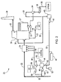
- a flue gas stream 22 leaves a boiler and travels to a particle collector 24.
- Particle collector 24 may be a baghouse, an electrostatic precipitator, a venturi-type scrubber or any similar apparatus that can facilitate the removal of particles from flue gas stream 22.
- Ash and other particulate contaminants present in flue gas stream 22 are collected in particle collector 24.
- the collected particulate contaminants may be disposed of or may be recycled within WFGD system 20.
- flue gas stream 22 travels to a wet scrubber 26.
- Wet scrubber 26 removes acidic gases such as SO 2 from the flue gas by exposing the flue gas to an alkaline reagent.
- the alkaline reagent can be limestone, lime, or any other alkaline compound, in a slurry, which is sprayed into flue gas stream 22 as droplets.
- the unreacted alkaline reagent can be recirculated within wet scrubber 26 by utilizing a slurry recirculating line 27 to introduce the alkaline reagent to wet scrubber 26.
- the reacted alkaline reagent is fully oxidized to form gypsum by exposing it to air from oxidation air supply line 23.
- Flue gas stream 22 After contacting the flue gas stream 22 with the alkaline reagent, the flue gas stream is transported to a stack 28 for release into the atmosphere. Flue gas stream 22 may be subjected to other reagents, or one or more devices, that facilitate the removal of contaminants prior to being released into the atmosphere via stack 28. Other treatments include, but are not limited to, mercury removal via contact with a reagent such as activated carbon, additional particulate collection, and the like.
- the reaction of the alkaline reagent with the acidic components of flue gas stream 22 in wet scrubber 26 produces salt and water.
- HCl and HF gases react to form water soluble salts that dissociate to form free Cl - and F - ions in the alkaline reagent.
- the increase of chloride ions tends to corrode the system and results in a chloride concentration in the alkaline reagent, which hinders the removal of acidic components from flue gas stream 22.
- purge liquid 30 to control the chloride level within the system. Purge liquid 30 typically also removes fine particulate material that is present in wet scrubber 26. Purge liquid 30 is typically sent to a wastewater treatment system or plant before it is discharged into the environment.
- Purge liquid 30 is discharged from wet scrubber 26 at point 32. After it is discharged from wet scrubber 26, purge liquid 30 is then sent to a holding tank or other system component that diverts the purge liquid to be transported to a wastewater treatment plant.
- Purge liquid 30 is mainly water, reacted and unreacted alkaline reagent and contains water soluble ions such as Cl - , however some particulates, known as "fines" may be in the purge liquid as well.
- purge liquid 30 is transported from wet scrubber 26 to hydrocyclone 34.
- Hydrocyclone 34 utilizes centrifugal force to separate particulate matter from the purge liquid.
- the particulate matter, together with a small amount of purge liquid 30, referred together as underflow liquid, drops down into a tank, a reservoir, or a vacuum filter 36 and can then be transported through process stream 38 to a separate system or apparatus used to collectgypsum.
- purge liquid 30 After purge liquid 30 reaches storage tank 40, the purge liquid travels via a pump 42 to a solids mixer 44.
- a process heater 46 may be installed to be in contact with purge liquid 30 as it is transported by pump 42 to solids mixer 44.
- Process heater 46 which can be electric or steam driven, is used to heat the purge liquid prior to delivering it to solids mixer 44.
- fly ash 48 A portion of collected fly ash 48 from particle collector 24 is transported to the solids mixer 44 as well. Fly ash 48 may be directed to solids mixer 44 from particle collector 24 by fluidized troughs, pneumatic transfer, or by any other means for transporting dry ash known by those skilled in the art.
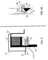
- control valve 50 is optionally connected to a user interface 52, which may be, for example, a keyboard, a monitor or a computer, or other device that allows a user to increase, decrease or stop the transportation of purge liquid 30 into solids mixer 44. Additionally, as shown in FIG. 3 , control valve 50 may optionally be connected to a device 51, which measures the temperature at a point 53 located behind particle collector 24.
- a sliding gate, rotary valve or other control mechanism 54 may be used to regulate the amount of fly ash 48 that enters solids mixer 44.
- control mechanism 54 may be connected to a user interface 56 that allows a user to increase, decrease or stop the transportation of fly ash 48 to solids mixer 44. Excess fly ash 48 not directed to solids mixer 44 may be brought to an ash storage facility or an ash disposal system by process stream 58.
- Moistened fly ash 60 can be in a dry free flowing form or can be in a slurry form.
- any unreacted alkaline particles i.e. calcium and/or magnesium
- the activated alkaline particles in moistened fly ash 60 are utilized to remove contaminants from flue gas stream 22.
- the proportions of fly ash 48 and purge liquid 30 are controlled to ensure that moistened fly ash 60 remains dry, fluffy and free flowing.
- the ratio of fly ash 48 to purge liquid 30 is maintained sufficiently high to keep moistened fly ash 60 free flowing.
- the moistened fly ash contains between about 94% to about 98% by weight of fly ash based on the total weight of moistened fly ash 60.
- the amount of fly ash in moistened fly ash 60 is typically between about 94% and about 95% by weight of the total weight of the moistened fly ash.
- the moisture of the moistened fly ash 60 in solids mixer 44 is monitored by a humidistat 62 which is operatively connected to solids mixer 44.
- the moistened fly ash 60 contains more purge liquid 30 making the moistened fly ash more slurry-like.
- Moistened fly ash 60 of this embodiment is formed by mixing purge liquid 30 with fly ash 48 in solids mixer 44. To form the slurry-like moistened fly ash 60, the moistened fly ash contains about 30% to about 50% by weight of fly ash based on the total weight of the moistened fly ash.
- Utilizing moistened fly ash 60 in a dry free-flowing form is advantageous in systems that have limited space or have limited access to water sources. Utilizing moistened fly ash 60 in a slurry-like form is advantageous in systems that have flue gas streams with very high temperatures or contain a high amount of sulfur therein.
- moistened fly ash 60 is formed, either in its substantially free flowing or slurry form, it is then introduced to newly produced flue gas 22.
- Moistened fly ash 60 is typically injected into flue gas stream 22 at a position 64 upstream of particle collector 24.
- moistened fly ash 60 can be injected into flue gas stream 22 at any position that allows the moistened fly ash to contact and remove contaminants from the flue gas stream.
- Moistened fly ash 60 may be transported from solids mixer 44 to position 64 by a pump 61.
- air from pump 65 may be introduced to moistened fly ash 60 before it is introduced to flue gas stream 22.
- moistened ash 60 flows out of solids mixer 44 through mixer outlets 66 and down an ash injection chute 68.
- Ash injection chute 68 can be a simple flat plate or it may have a perforated or sawtooth design. Ash injection chute 68 promotes even distribution of the moistened fly ash across the width of the duct flue gas stream 22 travels in.
- Below ash injection chute 68 may be a false wall 70, which accelerates the speed of flue gas stream 22 to the proper velocity at which moistened fly ash 60 can be entrained into the flue gas stream.
- the dehumidified fly ash acts as a reagent to remove SO 2 , HCl and other acidic components in flue gas stream 22. [Not sure it matters, but the "removal" reaction occurs as the ash dries - not afterwards; the process of drying helps to remove the acid components]
- the dehumidified fly ash is brought back to particulate collector 24 where it is collected or removed as discussed in more detail above. If organic acids such as dibasic acid (DBA) or adipic acid are used in system 20, they are evaporated and captured in particle collector 24. If a fabric filter is used in the system, even greater SO 2 and HCl removal is achieved.
- DBA dibasic acid
- adipic acid adipic acid
- the embodiments described herein decrease the amount of fresh alkaline reagent needed by the system overall. Further, the embodiments described herein reduce or eliminate transporting used purge liquid 30 to a wastewater treatment plant.
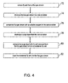
- step 72 at least a portion of the fly ash present in flue gas stream 22 is removed from the flue gas stream.
- the fly ash is removed by introducing flue gas stream 22 into a particle collector 24.
- step 74 flue gas stream 22 is then introduced to a wet scrubber 26, where in step 76 it is contacted with an alkaline reagent.
- the alkaline reagent is typically an alkaline compound that reacts with any acidic components present in flue gas stream 22. The reaction of the alkaline reagent with the acidic components results in the production of corrosive chloride ions.
- a purge liquid 30 contains corrosive chloride ions and removes them from wet scrubber 26. After collecting at least a portion of the chloride ions from wet scrubber 26, purge liquid 30 is discharged from the wet scrubber and sent to hydrocyclone 34.
- step 80 the purge liquid is combined with at least a portion of fly ash 48 collected from particle collector 24.
- the combination of purge liquid 30 and fly ash 48 form a moistened fly ash 60.
- step 82 moistened fly ash 60 is then injected into flue gas stream 22 at a point 64 upstream of particle collector 24.
- the moisture from moistened fly ash 60 is evaporated therefrom, thereby humidifying flue gas stream 22 and dehumidifying the fly ash, which then serves as a reactant to collect and remove contaminants from the flue gas stream.
Landscapes
- Engineering & Computer Science (AREA)
- Chemical & Material Sciences (AREA)
- Health & Medical Sciences (AREA)
- Biomedical Technology (AREA)
- Environmental & Geological Engineering (AREA)
- Analytical Chemistry (AREA)
- General Chemical & Material Sciences (AREA)
- Oil, Petroleum & Natural Gas (AREA)
- Chemical Kinetics & Catalysis (AREA)
- Life Sciences & Earth Sciences (AREA)
- Sustainable Development (AREA)
- Treating Waste Gases (AREA)
Claims (11)
- Procédé de retrait des contaminants d'un courant de gaz de combustion (22), le procédé comprenant:le retrait des cendres volantes d'un courant de gaz de combustion (22) en utilisant un collecteur de particules (24), le collecteur de particules (24) étant un filtre à manches ou un précipitateur électrostatique ou un filtre en tissu;la mise en contact du courant de gaz de combustion (22) avec un réactif alcalin dans un dépoussiéreur humide (26) placé en aval du collecteur de particules (24);le rejet d'un liquide de purge (30) du dépoussiéreur humide (26);la combinaison d'au moins une partie du liquide de purge (30) avec au moins une partie des cendres volantes pour former des cendres volantes humidifiées (60); etl'injection d'au moins une partie des cendres volantes humidifiées (60) dans le courant de gaz de combustion (22) en amont du collecteur de particules (24), les cendres volantes humidifiées (60) retirant ainsi au moins une partie des contaminants présents dans le courant de gaz de combustion (22).
- Procédé selon la revendication 1 dans lequel, après rejet du liquide de purge (30) du dépoussiéreur humide (26), les particules présentes dans ledit liquide de purge (30) sont retirées de celui-ci ou réduites, avant combinaison d'au moins une partie du liquide de purge (30) avec au moins une partie des cendres volantes.
- Procédé selon l'une des revendications précédentes dans lequel ledit réactif alcalin est choisi parmi la chaux et le calcaire.
- Procédé selon l'une des revendications précédentes dans lequel ledit liquide de purge (30) comprend de l'eau.
- Procédé selon l'une des revendications précédentes dans lequel la partie des cendres volantes est présente dans les cendres volantes humidifiées (60) dans une quantité comprise entre environ 94 % et environ 98 % en poids, rapporté au poids total des cendres volantes humidifiées (60).
- Procédé selon la revendication 5 dans lequel la partie des cendres volantes est présente dans les cendres volantes humidifiées (60) dans une quantité comprise entre environ 94 % et environ 95 % en poids, rapporté au poids total des cendres volantes humidifiées (60).
- Procédé selon les revendications 1 à 4 dans lequel la partie des cendres volantes est présente dans les cendres volantes humidifiées (60) dans une quantité comprise entre environ 30 % et environ 50 % en poids, rapporté au poids total des cendres volantes humidifiées (60).
- Procédé selon l'une des revendications précédentes dans lequel les contaminants comprennent des SOx, du HCl et des gaz acides.
- Procédé selon l'une des revendications précédentes comprenant les étapes consistant à:transporter les cendres volantes à un mélangeur de matières solides;combiner les cendres volantes avec un liquide de purge (30) qui a été acheminé depuis un dépoussiéreur humide (26) au mélangeur de matières solides;former des cendres volantes humidifiées (60) à partir des cendres volantes et du liquide de purge (30); etinjecter le mélange de cendres volantes humidifiées (60) dans le courant de gaz de combustion (22), réduisant ainsi la quantité de liquide de purge (30) envoyée à une installation de traitement des eaux usées.
- Système pour réduire ou éliminer la quantité de liquide de purge (30) envoyée à une installation de traitement des eaux usées dans un système de traitement de gaz de combustion (20), le système (20) comprenant:des moyens (24) pour retirer les cendres volantes d'un courant de gaz de combustion (22) et détourner les cendres volantes vers un mélangeur de matières solides (44), les moyens (24) pour retirer les cendres volantes d'un courant de gaz de combustion (22) étant un filtre à manches ou un précipitateur électrostatique ou un filtre en tissu;des moyens pour rejeter un liquide de purge (30) d'un dépoussiéreur humide (26) placé en aval du collecteur de particules (24) et détourner le liquide de purge (30) vers le mélangeur de matières solides,dans lequel les cendres volantes retirées sont combinées avec au moins une partie du liquide de purge (30) pour former des cendres volantes humidifiées (60) dans le mélangeur de matières solides (44); etdes moyens (66) pour injecter les cendres volantes humidifiées (60) dans le courant de gaz de combustion (22),dans lequel les moyens pour injecter les cendres volantes humidifiées (60) dans le courant de gaz de combustion (22) se situent en amont des moyens (24) pour retirer les cendres volantes du courant de gaz de combustion (22).
- Système selon la revendication 10 dans lequel le liquide de purge (30) comprend de l'eau.
Applications Claiming Priority (2)
| Application Number | Priority Date | Filing Date | Title |
|---|---|---|---|
| US11/486,705 US7524470B2 (en) | 2006-07-13 | 2006-07-13 | Reduced liquid discharge in wet flue gas desulfurization |
| PCT/US2007/069602 WO2008008568A1 (fr) | 2006-07-13 | 2007-05-24 | Évacuation de liquide réduit dans une désulfurisation de gaz de combustion par voie humide |
Publications (2)
| Publication Number | Publication Date |
|---|---|
| EP2040823A1 EP2040823A1 (fr) | 2009-04-01 |
| EP2040823B1 true EP2040823B1 (fr) | 2012-11-21 |
Family
ID=38693599
Family Applications (1)
| Application Number | Title | Priority Date | Filing Date |
|---|---|---|---|
| EP07797709A Not-in-force EP2040823B1 (fr) | 2006-07-13 | 2007-05-24 | Rejet réduit de liquide dans une désulfurisation de gaz de combustion par voie humide |
Country Status (4)
| Country | Link |
|---|---|
| US (1) | US7524470B2 (fr) |
| EP (1) | EP2040823B1 (fr) |
| TW (1) | TWI319328B (fr) |
| WO (1) | WO2008008568A1 (fr) |
Families Citing this family (23)
| Publication number | Priority date | Publication date | Assignee | Title |
|---|---|---|---|---|
| US7429365B2 (en) * | 2005-11-18 | 2008-09-30 | General Electric Company | Method and system for removing mercury from combustion gas |
| US7374733B2 (en) * | 2005-11-18 | 2008-05-20 | General Electric Company | Method and system for removing mercury from combustion gas |
| US7767174B2 (en) * | 2006-09-18 | 2010-08-03 | General Electric Company | Method and systems for removing mercury from combustion exhaust gas |
| US7662353B2 (en) * | 2007-02-14 | 2010-02-16 | General Electric Company | Methods and systems for removing mercury from combustion flue gas |
| US7544339B2 (en) * | 2007-03-27 | 2009-06-09 | General Electric Company | Method and apparatus for removing mercury from combustion exhaust gas |
| US7504081B2 (en) * | 2007-03-27 | 2009-03-17 | General Electric Company | Methods and apparatus to facilitate reducing mercury emissions |
| US7531153B2 (en) * | 2007-03-27 | 2009-05-12 | General Electric Company | Methods and apparatus for removing mercury from combustion flue gas |
| JP5384799B2 (ja) * | 2007-03-30 | 2014-01-08 | 三菱重工メカトロシステムズ株式会社 | 排ガス処理装置および排ガス処理方法 |
| US7833315B2 (en) * | 2008-02-26 | 2010-11-16 | General Electric Company | Method and system for reducing mercury emissions in flue gas |
| US9352274B2 (en) | 2014-01-02 | 2016-05-31 | Alstom Technology Ltd | Apparatus and method for evaporating waste water and reducing acid gas emissions |
| US9724638B2 (en) | 2014-01-02 | 2017-08-08 | General Electric Technology Gmbh | Apparatus and method for evaporating waste water and reducing acid gas emissions |
| JP2015178060A (ja) * | 2014-03-19 | 2015-10-08 | 住友大阪セメント株式会社 | 排ガス処理方法及び処理装置 |
| CN103977699A (zh) * | 2014-06-04 | 2014-08-13 | 长沙高必拓脱硫工程有限公司 | 一种气动乳化氧化锌脱硫系统及其工艺流程 |
| US9650269B2 (en) | 2014-11-25 | 2017-05-16 | General Electric Technology Gmbh | System and method for reducing gas emissions from wet flue gas desulfurization waste water |
| US10350542B2 (en) | 2016-04-29 | 2019-07-16 | General Electric Company | Wet flue gas desulfurization system with zero waste water liquid discharge |
| JP7005166B2 (ja) | 2016-04-29 | 2022-01-21 | ゼネラル エレクトリック テクノロジー ゲゼルシャフト ミット ベシュレンクテル ハフツング | 廃水を蒸発させて酸性ガス排出を減らすための装置及び方法 |
| DK3323496T3 (da) | 2016-11-18 | 2020-12-14 | General Electric Technology Gmbh | Apparat og fremgangsmåde til reduktion af emissioner af sur gas med nul-væskeudledning af spildevand |
| CN108126507B (zh) * | 2017-12-26 | 2020-06-30 | 福建龙净环保股份有限公司 | 用于湿法脱硫的水处理工艺系统及方法 |
| CN109157961A (zh) * | 2018-11-14 | 2019-01-08 | 中国科学院过程工程研究所 | 一种电解铝碳素阳极焙烧烟气的多污染物联合脱除装置、方法及用途 |
| JP7498258B2 (ja) * | 2019-07-23 | 2024-06-11 | クリーナー パワー ソリューションズ オサケユキチュア | 浄化組成物、浄化組成物の製造方法、及び浄化組成物による煙道ガスの浄化方法 |
| CN111928286B (zh) * | 2020-08-14 | 2021-09-14 | 西安热工研究院有限公司 | 一种适应多工况的脱硫废水零排放处理方法及系统 |
| US11439947B2 (en) * | 2020-08-28 | 2022-09-13 | Andritz Aktiebolag | System and method for mixing recirculating combustion ash with hydrated lime and water |
| CN112221340B (zh) * | 2020-10-20 | 2021-09-14 | 威海市正大环保设备股份有限公司 | 塔外增湿循环半干法脱硫除尘一体化方法 |
Family Cites Families (11)
| Publication number | Priority date | Publication date | Assignee | Title |
|---|---|---|---|---|
| US3995006A (en) * | 1973-04-05 | 1976-11-30 | The Babcock & Wilcox Company | Sulphur dioxide absorption system |
| DE3232077C2 (de) * | 1982-08-28 | 1986-10-23 | Rheinisch-Westfälisches Elektrizitätswerk AG, 4300 Essen | Verfahren und Vorrichtung zur Entfernung von Schwefeldioxid und anderen Schadstoffen aus Rauchgasen |
| US4956162A (en) | 1986-06-16 | 1990-09-11 | Electric Power Research Institute, Inc. | Process for removal of particulates and SO2 from combustion gases |
| FI885299A0 (fi) | 1987-03-18 | 1988-11-16 | Radian Corp | Behandlingsfoerfarande foer avfallsgas. |
| US5439658A (en) | 1993-09-03 | 1995-08-08 | The Babcock & Wilcox Company | Regenerable magnesium dry scrubbing |
| US5630991A (en) | 1994-08-16 | 1997-05-20 | General Electric Co. | Limestone-based wet flue gas desulfurization process |
| TW330153B (en) | 1995-05-10 | 1998-04-21 | Mitsubishi Heavy Industry Kk | Flue gas desulfurization device with slurry filtration device |
| US6372187B1 (en) * | 1998-12-07 | 2002-04-16 | Mcdermott Technology, Inc. | Alkaline sorbent injection for mercury control |
| US6695018B2 (en) | 2002-06-10 | 2004-02-24 | The Babcock & Wilcox Company | Collection scoop for flue gas desulfurization systems with bleed streams or ex situ forced oxidation |
| US6997119B2 (en) | 2002-07-23 | 2006-02-14 | Radway Jerrold E | Combustion emissions control and utilization of byproducts |
| SE523667C2 (sv) | 2002-09-20 | 2004-05-11 | Alstom Switzerland Ltd | Förfarande och anordning för avskiljning av gasformiga föroreningar från varma gaser medelst partikelformigt absorbentmaterial samt blandare för befuktning av absorbentmaterialet |
-
2006
- 2006-07-13 US US11/486,705 patent/US7524470B2/en active Active
-
2007
- 2007-05-24 EP EP07797709A patent/EP2040823B1/fr not_active Not-in-force
- 2007-05-24 WO PCT/US2007/069602 patent/WO2008008568A1/fr not_active Ceased
- 2007-07-12 TW TW096125452A patent/TWI319328B/zh not_active IP Right Cessation
Also Published As
| Publication number | Publication date |
|---|---|
| TWI319328B (en) | 2010-01-11 |
| EP2040823A1 (fr) | 2009-04-01 |
| US7524470B2 (en) | 2009-04-28 |
| TW200810826A (en) | 2008-03-01 |
| US20080011158A1 (en) | 2008-01-17 |
| WO2008008568A1 (fr) | 2008-01-17 |
Similar Documents
| Publication | Publication Date | Title |
|---|---|---|
| US7641876B2 (en) | Reduced liquid discharge in wet flue gas desulfurization | |
| US7524470B2 (en) | Reduced liquid discharge in wet flue gas desulfurization | |
| JP3881375B2 (ja) | 煙道ガス洗浄装置 | |
| US8277545B2 (en) | Method of reducing an amount of mercury in a flue gas | |
| EP2026897B1 (fr) | Procédé et système intégré de lavage de gaz de combustion sec et humide | |
| US5827352A (en) | Method for removing mercury from a gas stream and apparatus for same | |
| CA2622064C (fr) | Procede d'elimination de trioxyde de soufre dans un flux de gaz de combustion | |
| US4613487A (en) | Flue gas desulfurization process | |
| US4795619A (en) | Removal of acid gases in dry scrubbing of hot gases | |
| CS203105B2 (en) | Method of removing the sulphur dioxide and other acidic components from the combustion products | |
| HK187795A (en) | A method of improving the hg-removing capability of a flue gas cleaning process | |
| CZ58899A3 (cs) | Způsob a zařízení pro zpracování spalin | |
| CN1188425A (zh) | 燃烧废气干脱硫的方法 | |
| US9650269B2 (en) | System and method for reducing gas emissions from wet flue gas desulfurization waste water | |
| CA2622549C (fr) | Elimination de trioxyde de soufre d'un flux de gaz de combustion | |
| US4670238A (en) | Recycled sorbent flue gas desulfurization | |
| JPH10305210A (ja) | 排煙処理方法及び設備 | |
| JPH06126127A (ja) | 脱塵脱硫同時処理方法および装置 | |
| CZ297164B6 (cs) | Zpusob zpracování spalin | |
| JP3564296B2 (ja) | 排煙処理方法 | |
| EP1142624B1 (fr) | Dispositif et procédé pour le traitement des gaz de combustion | |
| US20080233028A1 (en) | Process and system for reducing sulfur trioxide emissions | |
| CA2925708C (fr) | Systeme d'epurateur a sec par circulation et procede | |
| JPS649069B2 (fr) | ||
| CA1168026A (fr) | Methode et dispositif de captage a sec des cendres volantes de cheminees |
Legal Events
| Date | Code | Title | Description |
|---|---|---|---|
| PUAI | Public reference made under article 153(3) epc to a published international application that has entered the european phase |
Free format text: ORIGINAL CODE: 0009012 |
|
| 17P | Request for examination filed |
Effective date: 20090109 |
|
| AK | Designated contracting states |
Kind code of ref document: A1 Designated state(s): AT BE BG CH CY CZ DE DK EE ES FI FR GB GR HU IE IS IT LI LT LU LV MC MT NL PL PT RO SE SI SK TR |
|
| AX | Request for extension of the european patent |
Extension state: AL BA HR MK RS |
|
| 17Q | First examination report despatched |
Effective date: 20100322 |
|
| GRAP | Despatch of communication of intention to grant a patent |
Free format text: ORIGINAL CODE: EPIDOSNIGR1 |
|
| DAX | Request for extension of the european patent (deleted) | ||
| GRAS | Grant fee paid |
Free format text: ORIGINAL CODE: EPIDOSNIGR3 |
|
| GRAA | (expected) grant |
Free format text: ORIGINAL CODE: 0009210 |
|
| AK | Designated contracting states |
Kind code of ref document: B1 Designated state(s): AT BE BG CH CY CZ DE DK EE ES FI FR GB GR HU IE IS IT LI LT LU LV MC MT NL PL PT RO SE SI SK TR |
|
| REG | Reference to a national code |
Ref country code: GB Ref legal event code: FG4D |
|
| REG | Reference to a national code |
Ref country code: CH Ref legal event code: EP |
|
| REG | Reference to a national code |
Ref country code: AT Ref legal event code: REF Ref document number: 584748 Country of ref document: AT Kind code of ref document: T Effective date: 20121215 |
|
| REG | Reference to a national code |
Ref country code: IE Ref legal event code: FG4D |
|
| REG | Reference to a national code |
Ref country code: DE Ref legal event code: R096 Ref document number: 602007026864 Country of ref document: DE Effective date: 20130117 |
|
| REG | Reference to a national code |
Ref country code: NL Ref legal event code: VDEP Effective date: 20121121 |
|
| REG | Reference to a national code |
Ref country code: AT Ref legal event code: MK05 Ref document number: 584748 Country of ref document: AT Kind code of ref document: T Effective date: 20121121 |
|
| REG | Reference to a national code |
Ref country code: LT Ref legal event code: MG4D |
|
| PG25 | Lapsed in a contracting state [announced via postgrant information from national office to epo] |
Ref country code: SE Free format text: LAPSE BECAUSE OF FAILURE TO SUBMIT A TRANSLATION OF THE DESCRIPTION OR TO PAY THE FEE WITHIN THE PRESCRIBED TIME-LIMIT Effective date: 20121121 Ref country code: ES Free format text: LAPSE BECAUSE OF FAILURE TO SUBMIT A TRANSLATION OF THE DESCRIPTION OR TO PAY THE FEE WITHIN THE PRESCRIBED TIME-LIMIT Effective date: 20130304 Ref country code: FI Free format text: LAPSE BECAUSE OF FAILURE TO SUBMIT A TRANSLATION OF THE DESCRIPTION OR TO PAY THE FEE WITHIN THE PRESCRIBED TIME-LIMIT Effective date: 20121121 Ref country code: LT Free format text: LAPSE BECAUSE OF FAILURE TO SUBMIT A TRANSLATION OF THE DESCRIPTION OR TO PAY THE FEE WITHIN THE PRESCRIBED TIME-LIMIT Effective date: 20121121 |
|
| PG25 | Lapsed in a contracting state [announced via postgrant information from national office to epo] |
Ref country code: PL Free format text: LAPSE BECAUSE OF FAILURE TO SUBMIT A TRANSLATION OF THE DESCRIPTION OR TO PAY THE FEE WITHIN THE PRESCRIBED TIME-LIMIT Effective date: 20121121 Ref country code: PT Free format text: LAPSE BECAUSE OF FAILURE TO SUBMIT A TRANSLATION OF THE DESCRIPTION OR TO PAY THE FEE WITHIN THE PRESCRIBED TIME-LIMIT Effective date: 20130321 Ref country code: SI Free format text: LAPSE BECAUSE OF FAILURE TO SUBMIT A TRANSLATION OF THE DESCRIPTION OR TO PAY THE FEE WITHIN THE PRESCRIBED TIME-LIMIT Effective date: 20121121 Ref country code: LV Free format text: LAPSE BECAUSE OF FAILURE TO SUBMIT A TRANSLATION OF THE DESCRIPTION OR TO PAY THE FEE WITHIN THE PRESCRIBED TIME-LIMIT Effective date: 20121121 Ref country code: GR Free format text: LAPSE BECAUSE OF FAILURE TO SUBMIT A TRANSLATION OF THE DESCRIPTION OR TO PAY THE FEE WITHIN THE PRESCRIBED TIME-LIMIT Effective date: 20130222 Ref country code: BE Free format text: LAPSE BECAUSE OF FAILURE TO SUBMIT A TRANSLATION OF THE DESCRIPTION OR TO PAY THE FEE WITHIN THE PRESCRIBED TIME-LIMIT Effective date: 20121121 |
|
| PG25 | Lapsed in a contracting state [announced via postgrant information from national office to epo] |
Ref country code: AT Free format text: LAPSE BECAUSE OF FAILURE TO SUBMIT A TRANSLATION OF THE DESCRIPTION OR TO PAY THE FEE WITHIN THE PRESCRIBED TIME-LIMIT Effective date: 20121121 |
|
| PG25 | Lapsed in a contracting state [announced via postgrant information from national office to epo] |
Ref country code: EE Free format text: LAPSE BECAUSE OF FAILURE TO SUBMIT A TRANSLATION OF THE DESCRIPTION OR TO PAY THE FEE WITHIN THE PRESCRIBED TIME-LIMIT Effective date: 20121121 Ref country code: DK Free format text: LAPSE BECAUSE OF FAILURE TO SUBMIT A TRANSLATION OF THE DESCRIPTION OR TO PAY THE FEE WITHIN THE PRESCRIBED TIME-LIMIT Effective date: 20121121 Ref country code: BG Free format text: LAPSE BECAUSE OF FAILURE TO SUBMIT A TRANSLATION OF THE DESCRIPTION OR TO PAY THE FEE WITHIN THE PRESCRIBED TIME-LIMIT Effective date: 20130221 Ref country code: CZ Free format text: LAPSE BECAUSE OF FAILURE TO SUBMIT A TRANSLATION OF THE DESCRIPTION OR TO PAY THE FEE WITHIN THE PRESCRIBED TIME-LIMIT Effective date: 20121121 Ref country code: SK Free format text: LAPSE BECAUSE OF FAILURE TO SUBMIT A TRANSLATION OF THE DESCRIPTION OR TO PAY THE FEE WITHIN THE PRESCRIBED TIME-LIMIT Effective date: 20121121 |
|
| PG25 | Lapsed in a contracting state [announced via postgrant information from national office to epo] |
Ref country code: NL Free format text: LAPSE BECAUSE OF FAILURE TO SUBMIT A TRANSLATION OF THE DESCRIPTION OR TO PAY THE FEE WITHIN THE PRESCRIBED TIME-LIMIT Effective date: 20121121 Ref country code: RO Free format text: LAPSE BECAUSE OF FAILURE TO SUBMIT A TRANSLATION OF THE DESCRIPTION OR TO PAY THE FEE WITHIN THE PRESCRIBED TIME-LIMIT Effective date: 20121121 |
|
| PLBE | No opposition filed within time limit |
Free format text: ORIGINAL CODE: 0009261 |
|
| STAA | Information on the status of an ep patent application or granted ep patent |
Free format text: STATUS: NO OPPOSITION FILED WITHIN TIME LIMIT |
|
| 26N | No opposition filed |
Effective date: 20130822 |
|
| REG | Reference to a national code |
Ref country code: DE Ref legal event code: R097 Ref document number: 602007026864 Country of ref document: DE Effective date: 20130822 |
|
| PG25 | Lapsed in a contracting state [announced via postgrant information from national office to epo] |
Ref country code: MC Free format text: LAPSE BECAUSE OF FAILURE TO SUBMIT A TRANSLATION OF THE DESCRIPTION OR TO PAY THE FEE WITHIN THE PRESCRIBED TIME-LIMIT Effective date: 20121121 |
|
| REG | Reference to a national code |
Ref country code: CH Ref legal event code: PL |
|
| PG25 | Lapsed in a contracting state [announced via postgrant information from national office to epo] |
Ref country code: LI Free format text: LAPSE BECAUSE OF NON-PAYMENT OF DUE FEES Effective date: 20130531 Ref country code: CH Free format text: LAPSE BECAUSE OF NON-PAYMENT OF DUE FEES Effective date: 20130531 |
|
| REG | Reference to a national code |
Ref country code: IE Ref legal event code: MM4A |
|
| PG25 | Lapsed in a contracting state [announced via postgrant information from national office to epo] |
Ref country code: IE Free format text: LAPSE BECAUSE OF NON-PAYMENT OF DUE FEES Effective date: 20130524 |
|
| PG25 | Lapsed in a contracting state [announced via postgrant information from national office to epo] |
Ref country code: MT Free format text: LAPSE BECAUSE OF FAILURE TO SUBMIT A TRANSLATION OF THE DESCRIPTION OR TO PAY THE FEE WITHIN THE PRESCRIBED TIME-LIMIT Effective date: 20121121 |
|
| PG25 | Lapsed in a contracting state [announced via postgrant information from national office to epo] |
Ref country code: TR Free format text: LAPSE BECAUSE OF FAILURE TO SUBMIT A TRANSLATION OF THE DESCRIPTION OR TO PAY THE FEE WITHIN THE PRESCRIBED TIME-LIMIT Effective date: 20121121 Ref country code: CY Free format text: LAPSE BECAUSE OF FAILURE TO SUBMIT A TRANSLATION OF THE DESCRIPTION OR TO PAY THE FEE WITHIN THE PRESCRIBED TIME-LIMIT Effective date: 20121121 |
|
| PG25 | Lapsed in a contracting state [announced via postgrant information from national office to epo] |
Ref country code: LU Free format text: LAPSE BECAUSE OF NON-PAYMENT OF DUE FEES Effective date: 20130524 Ref country code: HU Free format text: LAPSE BECAUSE OF FAILURE TO SUBMIT A TRANSLATION OF THE DESCRIPTION OR TO PAY THE FEE WITHIN THE PRESCRIBED TIME-LIMIT; INVALID AB INITIO Effective date: 20070524 |
|
| REG | Reference to a national code |
Ref country code: FR Ref legal event code: PLFP Year of fee payment: 10 |
|
| PG25 | Lapsed in a contracting state [announced via postgrant information from national office to epo] |
Ref country code: IS Free format text: LAPSE BECAUSE OF FAILURE TO SUBMIT A TRANSLATION OF THE DESCRIPTION OR TO PAY THE FEE WITHIN THE PRESCRIBED TIME-LIMIT Effective date: 20121121 |
|
| REG | Reference to a national code |
Ref country code: DE Ref legal event code: R082 Ref document number: 602007026864 Country of ref document: DE Representative=s name: RUEGER, BARTHELT & ABEL, DE Ref country code: DE Ref legal event code: R082 Ref document number: 602007026864 Country of ref document: DE Representative=s name: RUEGER | ABEL PATENT- UND RECHTSANWAELTE, DE Ref country code: DE Ref legal event code: R082 Ref document number: 602007026864 Country of ref document: DE Ref country code: DE Ref legal event code: R082 Ref document number: 602007026864 Country of ref document: DE Representative=s name: RUEGER ABEL PATENTANWAELTE PARTGMBB, DE Ref country code: DE Ref legal event code: R082 Ref document number: 602007026864 Country of ref document: DE Representative=s name: RUEGER ABEL PATENT- UND RECHTSANWAELTE, DE |
|
| REG | Reference to a national code |
Ref country code: DE Ref legal event code: R082 Ref document number: 602007026864 Country of ref document: DE Representative=s name: RUEGER | ABEL PATENT- UND RECHTSANWAELTE, DE Ref country code: DE Ref legal event code: R082 Ref document number: 602007026864 Country of ref document: DE Representative=s name: RUEGER ABEL PATENTANWAELTE PARTGMBB, DE Ref country code: DE Ref legal event code: R082 Ref document number: 602007026864 Country of ref document: DE Representative=s name: RUEGER, BARTHELT & ABEL, DE Ref country code: DE Ref legal event code: R081 Ref document number: 602007026864 Country of ref document: DE Owner name: GENERAL ELECTRIC TECHNOLOGY GMBH, CH Free format text: FORMER OWNER: ALSTOM TECHNOLOGY LTD., BADEN, CH Ref country code: DE Ref legal event code: R082 Ref document number: 602007026864 Country of ref document: DE Representative=s name: RUEGER ABEL PATENT- UND RECHTSANWAELTE, DE |
|
| REG | Reference to a national code |
Ref country code: FR Ref legal event code: CD Owner name: ALSTOM TECHNOLOGY LTD, CH Effective date: 20161124 |
|
| REG | Reference to a national code |
Ref country code: FR Ref legal event code: PLFP Year of fee payment: 11 |
|
| PGFP | Annual fee paid to national office [announced via postgrant information from national office to epo] |
Ref country code: GB Payment date: 20170530 Year of fee payment: 11 Ref country code: FR Payment date: 20170525 Year of fee payment: 11 |
|
| PGFP | Annual fee paid to national office [announced via postgrant information from national office to epo] |
Ref country code: IT Payment date: 20170524 Year of fee payment: 11 |
|
| GBPC | Gb: european patent ceased through non-payment of renewal fee |
Effective date: 20180524 |
|
| PG25 | Lapsed in a contracting state [announced via postgrant information from national office to epo] |
Ref country code: IT Free format text: LAPSE BECAUSE OF NON-PAYMENT OF DUE FEES Effective date: 20180524 Ref country code: GB Free format text: LAPSE BECAUSE OF NON-PAYMENT OF DUE FEES Effective date: 20180524 Ref country code: FR Free format text: LAPSE BECAUSE OF NON-PAYMENT OF DUE FEES Effective date: 20180531 |
|
| PGFP | Annual fee paid to national office [announced via postgrant information from national office to epo] |
Ref country code: DE Payment date: 20190418 Year of fee payment: 13 |
|
| REG | Reference to a national code |
Ref country code: DE Ref legal event code: R119 Ref document number: 602007026864 Country of ref document: DE |
|
| PG25 | Lapsed in a contracting state [announced via postgrant information from national office to epo] |
Ref country code: DE Free format text: LAPSE BECAUSE OF NON-PAYMENT OF DUE FEES Effective date: 20201201 |
|
| P01 | Opt-out of the competence of the unified patent court (upc) registered |
Effective date: 20230523 |