EP2041026B2 - Kryogenes flüssigkeitsinjektionssystem zur massenverarbeitung von produkten sowie kühlverfahren mit diesem system - Google Patents
Kryogenes flüssigkeitsinjektionssystem zur massenverarbeitung von produkten sowie kühlverfahren mit diesem system Download PDFInfo
- Publication number
- EP2041026B2 EP2041026B2 EP07803959.1A EP07803959A EP2041026B2 EP 2041026 B2 EP2041026 B2 EP 2041026B2 EP 07803959 A EP07803959 A EP 07803959A EP 2041026 B2 EP2041026 B2 EP 2041026B2
- Authority
- EP
- European Patent Office
- Prior art keywords
- valve
- injection device
- cryogenic fluid
- central
- channel
- Prior art date
- Legal status (The legal status is an assumption and is not a legal conclusion. Google has not performed a legal analysis and makes no representation as to the accuracy of the status listed.)
- Active
Links
Images

Classifications
-
- F—MECHANICAL ENGINEERING; LIGHTING; HEATING; WEAPONS; BLASTING
- F25—REFRIGERATION OR COOLING; COMBINED HEATING AND REFRIGERATION SYSTEMS; HEAT PUMP SYSTEMS; MANUFACTURE OR STORAGE OF ICE; LIQUEFACTION SOLIDIFICATION OF GASES
- F25D—REFRIGERATORS; COLD ROOMS; ICE-BOXES; COOLING OR FREEZING APPARATUS NOT OTHERWISE PROVIDED FOR
- F25D3/00—Devices using other cold materials; Devices using cold-storage bodies
- F25D3/12—Devices using other cold materials; Devices using cold-storage bodies using solidified gases, e.g. carbon-dioxide snow
-
- B—PERFORMING OPERATIONS; TRANSPORTING
- B01—PHYSICAL OR CHEMICAL PROCESSES OR APPARATUS IN GENERAL
- B01F—MIXING, e.g. DISSOLVING, EMULSIFYING OR DISPERSING
- B01F35/00—Accessories for mixers; Auxiliary operations or auxiliary devices; Parts or details of general application
- B01F35/90—Heating or cooling systems
- B01F2035/98—Cooling
-
- B—PERFORMING OPERATIONS; TRANSPORTING
- B01—PHYSICAL OR CHEMICAL PROCESSES OR APPARATUS IN GENERAL
- B01F—MIXING, e.g. DISSOLVING, EMULSIFYING OR DISPERSING
- B01F35/00—Accessories for mixers; Auxiliary operations or auxiliary devices; Parts or details of general application
- B01F35/90—Heating or cooling systems
- B01F35/91—Heating or cooling systems using gas or liquid injected into the material, e.g. using liquefied carbon dioxide or steam
-
- B—PERFORMING OPERATIONS; TRANSPORTING
- B05—SPRAYING OR ATOMISING IN GENERAL; APPLYING FLUENT MATERIALS TO SURFACES, IN GENERAL
- B05B—SPRAYING APPARATUS; ATOMISING APPARATUS; NOZZLES
- B05B1/00—Nozzles, spray heads or other outlets, with or without auxiliary devices such as valves, heating means
- B05B1/30—Nozzles, spray heads or other outlets, with or without auxiliary devices such as valves, heating means designed to control volume of flow, e.g. with adjustable passages
- B05B1/3033—Nozzles, spray heads or other outlets, with or without auxiliary devices such as valves, heating means designed to control volume of flow, e.g. with adjustable passages the control being effected by relative coaxial longitudinal movement of the controlling element and the spray head
- B05B1/3073—Nozzles, spray heads or other outlets, with or without auxiliary devices such as valves, heating means designed to control volume of flow, e.g. with adjustable passages the control being effected by relative coaxial longitudinal movement of the controlling element and the spray head the controlling element being a deflector acting as a valve in co-operation with the outlet orifice
-
- B—PERFORMING OPERATIONS; TRANSPORTING
- B05—SPRAYING OR ATOMISING IN GENERAL; APPLYING FLUENT MATERIALS TO SURFACES, IN GENERAL
- B05B—SPRAYING APPARATUS; ATOMISING APPARATUS; NOZZLES
- B05B1/00—Nozzles, spray heads or other outlets, with or without auxiliary devices such as valves, heating means
- B05B1/30—Nozzles, spray heads or other outlets, with or without auxiliary devices such as valves, heating means designed to control volume of flow, e.g. with adjustable passages
- B05B1/32—Nozzles, spray heads or other outlets, with or without auxiliary devices such as valves, heating means designed to control volume of flow, e.g. with adjustable passages in which a valve member forms part of the outlet opening
- B05B1/323—Nozzles, spray heads or other outlets, with or without auxiliary devices such as valves, heating means designed to control volume of flow, e.g. with adjustable passages in which a valve member forms part of the outlet opening the valve member being actuated by the pressure of the fluid to be sprayed
-
- B—PERFORMING OPERATIONS; TRANSPORTING
- B05—SPRAYING OR ATOMISING IN GENERAL; APPLYING FLUENT MATERIALS TO SURFACES, IN GENERAL
- B05B—SPRAYING APPARATUS; ATOMISING APPARATUS; NOZZLES
- B05B15/00—Details of spraying plant or spraying apparatus not otherwise provided for; Accessories
- B05B15/60—Arrangements for mounting, supporting or holding spraying apparatus
- B05B15/65—Mounting arrangements for fluid connection of the spraying apparatus or its outlets to flow conduits
-
- F—MECHANICAL ENGINEERING; LIGHTING; HEATING; WEAPONS; BLASTING
- F25—REFRIGERATION OR COOLING; COMBINED HEATING AND REFRIGERATION SYSTEMS; HEAT PUMP SYSTEMS; MANUFACTURE OR STORAGE OF ICE; LIQUEFACTION SOLIDIFICATION OF GASES
- F25D—REFRIGERATORS; COLD ROOMS; ICE-BOXES; COOLING OR FREEZING APPARATUS NOT OTHERWISE PROVIDED FOR
- F25D3/00—Devices using other cold materials; Devices using cold-storage bodies
- F25D3/10—Devices using other cold materials; Devices using cold-storage bodies using liquefied gases, e.g. liquid air
Definitions
- the present invention relates to a device intended to inject, into an enclosure, a cryogenic fluid, under a pressure greater than that which prevails in the enclosure.
- a known device for implementing this process comprises several injection devices, arranged in the bottom of the tank, and supplied with liquid CO 2 by a set of pipes, this set being provided with a common control valve, unique.
- a device intended to inject into an enclosure a liquid capable of solidifying by expansion is known from the document EP-A-376 823 .
- the patent EP-744 578 describes an injection device making it possible to avoid the inconveniences caused by blockage incidents under normal conditions of use. This device is such that the connection between the stop valve and the injection nozzle is calculated so that a blockage possibly formed in said connection and said nozzle following a closing of the injection valve can be expelled towards the enclosure by the liquid under pressure when the injection valve is reopened.
- the device does not include means to prevent the formation of a blockage, but the expulsion of this blockage is possible as soon as it is restarted, so that it is possible to carry out a new injection at any time after the end of a previous injection period.
- this device can be blocked by the entry of the material to be cooled into the injection device, and therefore the use of this device is limited to the cooling of solid products.
- the present invention relates to an injection device intended to be fixed on the lower part of a container containing a product to be cooled in bulk, said injection device comprising a hollow cylindrical body in which is inserted a valve forced by a spring, said injection device comprising a through channel substantially parallel to said valve intended to be supplied with cryogenic fluid under pressure, one end of said through channel being connected to the cryogenic fluid supply system and the opposite end opening at the level of the valve seat.
- the spring is calibrated such that the valve cannot slide without being subjected to a pressure of the cryogenic fluid at least equal to a threshold pressure.
- a pressure of the cryogenic fluid at least equal to a threshold pressure.
- the device according to the invention it is impossible for material contained in the enclosure to be introduced into the device and create blockages requiring dismantling and cleaning, whatever the physical state of this material.
- the device according to the invention is therefore suitable for cooling products in liquid, pasty, solid or granular form.
- pasty product we mean any product whose viscosity is between liquid and solid.
- the device can advantageously replace the top cooling devices of tanks containing liquid or powdery products for which the prior art bottom cooling systems were not suitable.
- the cryogenic fluid used is liquid nitrogen or liquid CO 2 , particularly when the product to be cooled is a food product.
- the device according to the invention can be implemented with any type of cryogenic fluid.
- the device can include several transverse channels, one of the ends of which opens at the level of the valve seat.
- the device comprises n through channels, n being between 1 and 20, an even number, their number increases when the pressure of use of the cryogenic fluid decreases, said channels being arranged symmetrically with respect to the longitudinal axis of the valve.
- two channels are arranged symmetrically with respect to the longitudinal axis of the valve.
- the device of the invention is subjected to very significant temperature differences.
- the wall of the enclosure on which the device is fixed is generally at room temperature, while the opposite part of the device which receives the supply of cryogenic fluid is at a temperature of -196°C. Icing phenomena on the external surface of the enclosure are therefore inevitable. There may therefore be sticking to the frosted wall of the enclosure of the material to be cooled.
- the icing points become attachment points for the product contained in the enclosure. These points enlarge and eventually block the valve, no longer allowing the injection of cryogenic fluid.
- a thermal bridge that is to say to insert a part of insulating material between the element of the device in direct connection with the arrival of cryogenic fluid and the element of the device placed directly on the wall of the tank, the constituent elements then being dissociable.
- the thermal break can be made of any insulating material, in particular polymer resin or any other insulating plastic material.
- the various constituent elements are made of steel, preferably of stainless steel with the exception of the thermal bridge which is made of an insulating material.
- the different constituent elements are held together using a quick-disassembly connection or of the screwed or bayonet type or the like.
- the device according to the invention must be able to be dismantled in particular with a view to calibrating the spring forcing the valve, or for cleaning which is obligatory in the case of food products and which may be made necessary by abnormal operation or even by pollution. accidental.
- the device is connected to the cryogenic fluid supply via a flexible fluid conduit. This is to allow rapid dismantling. In fact, the flexible conduit does not have to be dismantled for cleaning.
- cleaning is further facilitated by maintaining the various constituent parts using a quick mechanical holding system (“quick” connection).
- quick mechanical holding system (“quick” connection).
- the device of the invention being intended to be used under pressure, means are provided so that only authorized personnel can dismantle the device.
- the constituent parts of the device are fixed together using tamper-proof screws and an anti-whiplash cable is fixed on the one hand to the flexible pipe, and on the other hand on either side of the “quick” connection, on the lower part of the device and on the upper part of it. Removal of the whip antibody cable is only possible using a specific key whose use is reserved for persons empowered.
- the device according to the invention is fixed tangentially to the previously perforated wall of the enclosure.
- the enclosure is a mixer
- part of the cryogenic fluid is already transformed into a solid before coming into contact with the mass to be cooled.
- the cryogenic solid is formed as soon as the fluid hits the valve seat in the space between the seat and the support. Taking into account the fact that it is the cryogenic solid which comes into contact with the material to be cooled, the cooling efficiency is therefore greater than that obtained with the devices of the prior art.
- the product can of course be moving in the enclosure, which promotes heat exchange and therefore cooling of the contents.
- the device according to the invention is fixed to the lower part of the mixing tank.
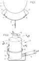
- FIG. 1 shows the lower part of an enclosure 1 on the wall of which are fixed, preferably by welding, two cryogenic fluid injection devices 3 conforming to the invention.
- the devices 3 are connected by a flexible pipe 4 and a heat-insulated pipe 5 to a solenoid valve 6 allowing the opening and closing of the supply of cryogenic fluid.
- FIG 2 shows in more detail an injection device 3, comprising an upper part 7 whose free end 8 is intended to be fixed on the external wall of an enclosure, and a lower part 9, the two parts being connected by a connector rapid 10.
- a flexible pipe 4 is connected to the lower part 9 of said device 3.
- a whipping cable 11 connecting the flexible pipe 4, the lower part 9 and the upper part 7. This cable is fixed using hooks safety 12 so that only authorized people can undo it, for example for dismantling.
- the injection device 3 comprises a body composed of two parts made integral, the lower part 9 and the upper part 7.
- the upper part is itself made up of 3 elements, a substantially cylindrical external wall 14 made of stainless steel, one end of which comes indirectly to rest on the lower part 9 and the other end of which is intended to be fixed on the wall of the enclosure.
- a piece of complementary shape called a thermal bridge, also hollow, insulating, inside which is placed a third element 16 in stainless steel crossed in its center by the valve 17 and by two through channels 18 opening onto the beveled upper part of the part 16 intended to receive the seat 13 of the valve 17.
- the central through opening of the part 16 comprises three zones, a central zone 19a of diameter substantially equal to that of the valve so that the valve can be placed sliding in this zone and a lower zone 19b of greater diameter, of such that it can receive around the axis of the valve the spring 19 forcing it.
- This spring 19 being held by the shoulder 20 formed between zones 19a and 19b.
- the zone 19c is of beveled shape, of wider diameter at its free end, the shape of the bevel being adapted to sealingly receive the valve seat when the valve is forced by the spring.
- the lower part 9 is made up of a single stainless steel element, of generally cylindrical shape. This part has a central blind recess 21 which when the device is mounted coincides with the opening 19b of the upper part. This recess is intended to receive the end of the valve held by the spring 19 and the calibration nut 22 of the spring.
- connection 26 It also comprises on either side of the blind recess two vertical channels 23, 24 which in the mounting position open at one end each into a through channel 18 and the other end into a perpendicular channel 25, one of which one end opens onto channel 23 and the other is intended to be connected to the cryogenic fluid supply system via connection 26.
- the lower part 9 is fixed to the central part 16 by screws 27 and 28.
- Screw 28 is an anti-disassembly screw allowing compliance with safety standards for pressure devices.
- Parts 14 and 15 are made integral with part 9 by connection 10 (shown on the figure 2 ).
- Connection 10 is a quick release connection. It could also be of the screwed or bayonet type or the like.
- valve 6 In operation, the valve 6 is open, and the cryogenic fluid is sent through the pipes 5 then the flexible 4 into the interior of the device 3, through the channel 25 then each of the channels 18.
- the pressurized fluid then exerts a pressure on the valve seat, a space is then formed between part 19c and the valve seat.
- the cryogenic solid begins to form in this space by the impact between the fluid and the valve seat, and is forced inside the enclosure.
- valve 6 When it is necessary to stop the supply of cryogenic fluid, valve 6 is closed.
- the invention also relates to the use of an injection device as described above for the cooling of bulk product.
- It also relates to a process for cooling bulk material contained in an enclosure, according to which a cryogenic fluid is injected into the heart of the material to be cooled using at least one injection device, preferably m injection distributed symmetrically in the lower part of the enclosure, m being an integer between 2 and 20, preferably an even number.
- the enclosure is a mixer.
- the process is particularly well suited to cooling any type of material whatever its physical state, particularly for liquid, pasty, solid or powdery products.
Landscapes
- Engineering & Computer Science (AREA)
- Chemical & Material Sciences (AREA)
- Chemical Kinetics & Catalysis (AREA)
- Combustion & Propulsion (AREA)
- Physics & Mathematics (AREA)
- Mechanical Engineering (AREA)
- Thermal Sciences (AREA)
- General Engineering & Computer Science (AREA)
- Filling Or Discharging Of Gas Storage Vessels (AREA)
Claims (9)
- Einspritzungsvorrichtung (3), an der Wand (2) des unteren Abschnitts eines Behälters (1) fixiert, der dazu bestimmt ist, ein Produkt zum Kühlen in loser Schüttung zu enthalten, wobei die Einspritzungsvorrichtung (3) einen hohlen zylindrischen Körper umfasst, in welchen ein durch eine Feder (19) forciertes Ventil (17) eingesetzt ist, wobei die Einspritzungsvorrichtung einen zu dem Ventil, das dazu bestimmt ist, mit kryogenem Fluid unter Druck gespeist zu werden, im Wesentlichen parallelen Durchgangskanal (18) umfasst, wobei ein Ende des Durchgangskanals mit dem Zuführungssystem des kryogenen Fluids verbunden ist, und das gegenüberliegende Ende auf Höhe des Sitzes (13) des Ventils mündet, dadurch gekennzeichnet, dass die Feder derart kalibriert ist, dass das Ventil nicht gleiten kann, ohne einem Druck des kryogenen Fluids, mindestens gleich einem Schwellendruck, unterworfen zu sein, und somit die Tatsache gestattet, dass, sobald der Druck des kryogenen Fluids unter einer bestimmten Schwelle liegt, der zum Gleitenlassen des Ventils (17) notwendige Druck nicht mehr erreicht wird und der Sitz (13) des Ventils auf abdichtende Weise gegen die Wand (2) zurückgesetzt wird.
- Einspritzungsvorrichtung nach Anspruch 1, umfassend n Durchgangskanäle (18), wobei n im Bereich zwischen 2 und 5 liegt, wobei die Kanäle bezüglich der Längsachse des Ventils (17) symmetrisch angeordnet sind.
- Einspritzungsvorrichtung nach Anspruch 1 oder 2, umfassend eine Wärmebrücke (15), das heißt, ein Teil aus isolierendem Material, zwischen dem Element der Einspritzungsvorrichtung in direkter Verbindung mit der Einführung des kryogenen Fluids und dem Element der direkt an der Wand des Entladungsgefäßes angebrachten Einspritzungsvorrichtung.
- Einspritzungsvorrichtung nach einem der Ansprüche 1 bis 3, umfassend:- ein unteres Element (9), das in einer Funktionsstellung am weitesten von der Wand des Entladungsgefäßes entfernt ist und das mit dem Zuführungssystem an kryogenem Fluid verbunden ist,- ein mittleres Element (16), von dem das untere Ende auf dem unteren Element abgestützt ist,- wobei das Ventil (17) gleitend in einem axial praktizierten Durchgangsloch in dem mittleren Element (16) angebracht ist, wobei der Sitz (13) des Ventils dicht gegen den abgeschrägten oberen Abschnitt (19c) des Durchgangslochs abgestützt ist,- eine das mittlere Element umgebende Wärmebrücke (15), von dem sich das untere Ende auf dem unteren Element abstützt,- ein Wandelement (14), von dem das untere Ende sich auf dem unteren Rand der Wärmebrücke abstützt und von dem das obere Ende dazu bestimmt ist, an der Wand des Entladungsgefäßes fixiert zu werden,wobei das untere Element umfasst:- mindestens einen Zuführungskanal (25), von dem ein Ende mit dem Zuführungssystem in Verbindung steht und das andere Ende mit einem Ende eines in dem Mittelstück (16) vorliegenden Durchgangskanals (23) in Verbindung steht, wobei der Durchgangskanal im Wesentlichen parallel zur Ventilachse verläuft, wobei sein anderes Ende auf Höhe des Sitzes des Ventils mündet,- eine mittlere Blindaussparung (21), dazu bestimmt, ein freies Ende der von der Kalibrierungsfeder (19) umgebenen Ventilachse aufzunehmen,wobei das axial in dem mittleren Element (16) ausgeführte Durchgangsloch drei Bereiche umfasst:- einen mittleren Bereich (19a), dessen Durchmesser im Wesentlichen gleich dem des Ventils ist, so dass das Ventil gleitend in diesen Bereich platziert werden kann,- den abgeschrägten oberen Abschnitt (19c),- und einen unteren Bereich (19b), dessen Durchmesser größer als der des mittleren Bereichs ist, so dass er um die Achse des Ventils die jenes forcierende Feder (19) aufnehmen kann,- wobei zwischen den zwei Bereichen, und zwar dem mittleren Bereich und dem unteren Bereich (19a, 19b), eine Schulter (20) ausgebildet ist und die Kalibrierungsfeder (19) in Montagestellung gegen die Schulter (20) gehalten wird.
- Einspritzungsvorrichtung nach einem der Ansprüche 1 bis 4, die mit der Zuführung an kryogenem Fluid über einen Fluidschlauch verbunden ist.
- Verwendung einer Einspritzungsvorrichtung nach einem der Ansprüche 1 bis 5, zur Kühlung von Produkt in loser Schüttung in fester, pastöser, flüssiger oder pulveriger Form.
- Verfahren zur Kühlung von Materialien in loser Schüttung, enthalten in einem Entladungsgefäß, nach welchem mittels mindestens einer Einspritzungsvorrichtung, wie in einem der Ansprüche 1 bis 5 beschrieben, vorzugsweise m symmetrisch in dem niederen Abschnitt des Entladungsgefäßes eingeteilten Einspritzungsvorrichtungen, ein kryogenes Fluid ins Herz des zu kühlenden Materials gespritzt wird, wobei m eine ganze Zahl im Bereich zwischen 2 und 20 ist, vorzugsweise eine gerade Zahl.
- Verfahren nach Anspruch 7, nach welchem das Entladungsgefäß ein Mischbottich sein kann.
- Verfahren nach einem der Ansprüche 7 oder 8, nach welchem das zu kühlende Material in pulveriger, flüssiger, pastöser oder fester Form vorliegt.
Priority Applications (1)
| Application Number | Priority Date | Filing Date | Title |
|---|---|---|---|
| PL07803959.1T PL2041026T5 (pl) | 2006-07-10 | 2007-06-28 | Układ wtryskiwania płynu kriogenicznego umożliwiający przetwarzanie produktów sypkich i sposób chłodzenia z jego wykorzystaniem |
Applications Claiming Priority (2)
| Application Number | Priority Date | Filing Date | Title |
|---|---|---|---|
| FR0652885A FR2903482B1 (fr) | 2006-07-10 | 2006-07-10 | Systeme d'injection de fluide cryogenique permettant le traitement de produits en vrac |
| PCT/FR2007/051549 WO2008007000A2 (fr) | 2006-07-10 | 2007-06-28 | Systeme d'injection de fluide cryogenique permettant le traitement de produits en vrac et procede de refroidissement le mettant en oeuvre |
Publications (3)
| Publication Number | Publication Date |
|---|---|
| EP2041026A2 EP2041026A2 (de) | 2009-04-01 |
| EP2041026B1 EP2041026B1 (de) | 2018-03-14 |
| EP2041026B2 true EP2041026B2 (de) | 2024-04-24 |
Family
ID=37928620
Family Applications (1)
| Application Number | Title | Priority Date | Filing Date |
|---|---|---|---|
| EP07803959.1A Active EP2041026B2 (de) | 2006-07-10 | 2007-06-28 | Kryogenes flüssigkeitsinjektionssystem zur massenverarbeitung von produkten sowie kühlverfahren mit diesem system |
Country Status (12)
| Country | Link |
|---|---|
| US (1) | US8621878B2 (de) |
| EP (1) | EP2041026B2 (de) |
| CN (1) | CN101489929B (de) |
| AU (1) | AU2007274158B2 (de) |
| BR (1) | BRPI0714376B1 (de) |
| DK (1) | DK2041026T3 (de) |
| ES (1) | ES2665876T5 (de) |
| FR (1) | FR2903482B1 (de) |
| PL (1) | PL2041026T5 (de) |
| PT (1) | PT2041026T (de) |
| WO (1) | WO2008007000A2 (de) |
| ZA (1) | ZA200900079B (de) |
Families Citing this family (18)
| Publication number | Priority date | Publication date | Assignee | Title |
|---|---|---|---|---|
| FR2942107B1 (fr) * | 2009-02-17 | 2011-03-25 | Air Liquide | Procede de traitement en ligne de milieux liquides ou pateux ou semi-liquides tels que les vendanges |
| FR2949647B1 (fr) * | 2009-09-10 | 2011-10-21 | Air Liquide | Procede et installation de refroidissement du contenu d'une enceinte mettant en oeuvre un systeme de convection forcee dans la partie haute de l'enceinte |
| DE102009048329A1 (de) | 2009-10-06 | 2011-04-07 | Messer France S.A.S | Vorrichtung zum Eindosieren eines kryogenen Mediums |
| FR2953370B1 (fr) | 2009-12-08 | 2012-08-03 | Air Liquide | Procede et installation de refroidissement et/ou surgelation de produits, notamment alimentaires, mettant en oeuvre l'injection de deux liquides cryogeniques |
| DE102010053976A1 (de) | 2010-12-09 | 2012-06-14 | Air Liquide Deutschland Gmbh | Verfahren zum Einspritzen eines Fluids, sowie eine entsprechende Vorrichtung und ein Mischbehälter |
| US20140000297A1 (en) * | 2012-06-29 | 2014-01-02 | Air Liquide Industrial U.S. L.P. | Production of Particles from Liquids or Suspensions with Liquid Cryogens |
| US9572555B1 (en) * | 2015-09-24 | 2017-02-21 | Ethicon, Inc. | Spray or drip tips having multiple outlet channels |
| GB2547489A (en) * | 2016-02-17 | 2017-08-23 | Linde Ag | Self-defrosting bottom injection nozzle |
| FR3064198B1 (fr) | 2017-03-23 | 2021-10-01 | Air Liquide France Ind | Dispositif d'injection d'un fluide cryogenique par le bas d'un melangeur |
| CN109114336B (zh) * | 2017-06-26 | 2020-10-30 | 中航光电科技股份有限公司 | 一种流体连接器、连接器组件及液冷系统 |
| DE102018006575A1 (de) * | 2018-08-21 | 2020-02-27 | Willmes GmbH | Vorrichtung und Verfahren zur Reinigung des Innenraums einer Presse zum Auspressen von flüssigkeitshaltigen Stoffen |
| CN109279604B (zh) * | 2018-11-30 | 2020-04-10 | 厦门理工学院 | 一种高密度二氧化碳成型设备 |
| JP7276958B2 (ja) * | 2019-07-05 | 2023-05-18 | 日本エア・リキード合同会社 | 冷凍撹拌装置 |
| CN110959745A (zh) * | 2019-12-17 | 2020-04-07 | 内蒙古蒙牛乳业(集团)股份有限公司 | 脆筒类冷饮巧克力凝冻装置及保持巧克力脆筒脆性的方法 |
| FR3106036B1 (fr) | 2020-01-10 | 2024-06-14 | Air Liquide France Ind | Procédé et Installation de transformation d’un produit liquide ou pâteux en particules surgelées dans un appareil de hachage rotatif (« cutter ») |
| DE102023109505A1 (de) | 2023-04-14 | 2024-10-17 | Messer France S.A.S | Vorrichtung zum Eindosieren eines kryogenen Mediums |
| DE102024100107A1 (de) | 2024-01-03 | 2025-07-03 | Messer France S.A.S. | Vorrichtung zum Eindosieren eines kryogenen Mediums |
| FR3162644A1 (fr) | 2024-05-31 | 2025-12-05 | L'air Liquide, Societe Anonyme Pour L'etude Et L'exploitation Des Procedes Georges Claude | Dispositif d’injection d’un fluide cryogénique par le bas d’un mélangeur |
Citations (3)
| Publication number | Priority date | Publication date | Assignee | Title |
|---|---|---|---|---|
| US3672181A (en) † | 1970-02-26 | 1972-06-27 | Lewis Tyree Jr | Method and apparatus for carbon dioxide cooling |
| US3815377A (en) † | 1970-02-26 | 1974-06-11 | L Tyree | System for cooling material using co{11 {11 snow |
| CN2348096Y (zh) † | 1998-05-06 | 1999-11-10 | 江苏石油勘探局石油工程技术研究院 | 一种液态二氧化碳注入装置 |
Family Cites Families (18)
| Publication number | Priority date | Publication date | Assignee | Title |
|---|---|---|---|---|
| US1898325A (en) * | 1931-08-26 | 1933-02-21 | Theodore H Venn | Atomizer |
| US3213634A (en) * | 1964-05-05 | 1965-10-26 | Air Reduction | Method and apparatus for individual quick freezing |
| US3848624A (en) * | 1972-09-29 | 1974-11-19 | Hollymatic Corp | Self-cleaning valve for refrigerating apparatus |
| ZA739374B (en) * | 1972-12-22 | 1974-11-27 | Air Prod & Chem | Method of chilling foodstuffs |
| ZA739376B (en) * | 1973-06-01 | 1974-11-27 | Air Prod & Chem | Apparatus for depositing solid carbon dioxide |
| US4056745A (en) * | 1976-01-08 | 1977-11-01 | Westinghouse Electric Corporation | Cryogen transfer coupling with adjustable throttle valve for rotating machinery |
| AU7358981A (en) * | 1980-07-30 | 1982-02-04 | Thermal Systems Ltd. | Injector for pressurised fluid |
| US4476686A (en) * | 1982-09-29 | 1984-10-16 | The Boc Group, Inc. | Methods and apparatus for chilling a product |
| JPS6488077A (en) * | 1987-09-29 | 1989-04-03 | Yoshio Ushiku | Cooling device |
| US4842198A (en) * | 1987-10-26 | 1989-06-27 | Chang Shih Chih | Device for damage protection against local flooding caused by sprinkler failure |
| FR2641854B1 (fr) * | 1988-12-28 | 1994-01-14 | Carboxyque Francaise | Procede et dispositif de regulation d'un debit de co2 liquide, et application a un tunnel de refroidissement |
| US5018667A (en) * | 1989-02-08 | 1991-05-28 | Cold Jet, Inc. | Phase change injection nozzle |
| US5299919A (en) * | 1991-11-01 | 1994-04-05 | Paul Marius A | Fuel injector system |
| US6176437B1 (en) * | 1993-10-15 | 2001-01-23 | Mona Skannerup | Blast gun for compressed air |
| FR2734624B1 (fr) * | 1995-05-24 | 1997-07-04 | Carboxyque Francaise | Dispositif d'injection de liquide sous pression dans une enceinte |
| US5595065A (en) * | 1995-07-07 | 1997-01-21 | Apd Cryogenics | Closed cycle cryogenic refrigeration system with automatic variable flow area throttling device |
| DE19621835A1 (de) * | 1996-05-31 | 1997-12-04 | Aga Ab | Expansionsdüse und Verfahren zur Erzeugung von Kohlendioxidschnee |
| FR2782153B1 (fr) * | 1998-08-05 | 2000-12-01 | Air Liquide | Dispositif et procede d'injection d'un fluide frigorigene dans un appareil melangeur de produits |
-
2006
- 2006-07-10 FR FR0652885A patent/FR2903482B1/fr not_active Expired - Fee Related
-
2007
- 2007-06-28 DK DK07803959.1T patent/DK2041026T3/en active
- 2007-06-28 EP EP07803959.1A patent/EP2041026B2/de active Active
- 2007-06-28 US US12/373,217 patent/US8621878B2/en active Active
- 2007-06-28 WO PCT/FR2007/051549 patent/WO2008007000A2/fr not_active Ceased
- 2007-06-28 BR BRPI0714376-1A patent/BRPI0714376B1/pt not_active IP Right Cessation
- 2007-06-28 ES ES07803959T patent/ES2665876T5/es active Active
- 2007-06-28 PL PL07803959.1T patent/PL2041026T5/pl unknown
- 2007-06-28 CN CN2007800261902A patent/CN101489929B/zh not_active Expired - Fee Related
- 2007-06-28 PT PT78039591T patent/PT2041026T/pt unknown
- 2007-06-28 AU AU2007274158A patent/AU2007274158B2/en not_active Ceased
-
2009
- 2009-01-05 ZA ZA200900079A patent/ZA200900079B/xx unknown
Patent Citations (3)
| Publication number | Priority date | Publication date | Assignee | Title |
|---|---|---|---|---|
| US3672181A (en) † | 1970-02-26 | 1972-06-27 | Lewis Tyree Jr | Method and apparatus for carbon dioxide cooling |
| US3815377A (en) † | 1970-02-26 | 1974-06-11 | L Tyree | System for cooling material using co{11 {11 snow |
| CN2348096Y (zh) † | 1998-05-06 | 1999-11-10 | 江苏石油勘探局石油工程技术研究院 | 一种液态二氧化碳注入装置 |
Also Published As
| Publication number | Publication date |
|---|---|
| BRPI0714376A2 (pt) | 2013-04-02 |
| US8621878B2 (en) | 2014-01-07 |
| EP2041026A2 (de) | 2009-04-01 |
| ES2665876T3 (es) | 2018-04-30 |
| FR2903482A1 (fr) | 2008-01-11 |
| BRPI0714376B1 (pt) | 2018-06-19 |
| WO2008007000A3 (fr) | 2008-03-13 |
| ES2665876T5 (es) | 2024-11-15 |
| CN101489929B (zh) | 2012-01-18 |
| CN101489929A (zh) | 2009-07-22 |
| FR2903482B1 (fr) | 2008-08-22 |
| EP2041026B1 (de) | 2018-03-14 |
| WO2008007000A2 (fr) | 2008-01-17 |
| ZA200900079B (en) | 2009-12-30 |
| PL2041026T5 (pl) | 2024-09-09 |
| AU2007274158B2 (en) | 2012-07-26 |
| DK2041026T3 (en) | 2018-05-22 |
| AU2007274158A1 (en) | 2008-01-17 |
| PT2041026T (pt) | 2018-05-14 |
| PL2041026T3 (pl) | 2018-08-31 |
| US20090314010A1 (en) | 2009-12-24 |
Similar Documents
| Publication | Publication Date | Title |
|---|---|---|
| EP2041026B2 (de) | Kryogenes flüssigkeitsinjektionssystem zur massenverarbeitung von produkten sowie kühlverfahren mit diesem system | |
| FR2698676A1 (fr) | Vanne thermosensible. | |
| EP0376823B2 (de) | Verfahren und Vorrichtung zur Mengenstromregelung von flüssigen CO2 und deren Anwendung für einen Kühltunnel | |
| CH632337A5 (fr) | Appareil a glacer, givrer ou embuer les recipients. | |
| EP3600682B1 (de) | Kryogenes flüssigkeitsinjektionssystem zur injektion im niedrigeren teil eines mischers | |
| EP1509735A1 (de) | Vorrichtung zum regeln der temperatur einer flüssigkeit, insbesondere wein | |
| EP1140339A1 (de) | Verfahren und gerät zum regulierten einspritzen von flüssigem kohlendioxid in eine unter druck stehende flüssigkeit | |
| FR2945526A1 (fr) | Dispositif de distribution pour distribuer et conserver un liquide contenu dans une bouteille | |
| EP0417004B1 (de) | Verfahren, um den Druck beim Füllen einer zweiphasigen Produktlagerung unter einem vorbestimmten Limit zu halten und die dazugehörige Kondensiereinrichtung | |
| EP0932007A1 (de) | Vorrichtung und Verfahren zum Filtern von einer kryogenischen Flüssigkeit | |
| EP2912365A2 (de) | Verfahren und vorrichtung zur befüllung eines tanks mit einer kryogenen flüssigkeit | |
| EP0744578B1 (de) | Vorrichtung zur Einspritzung einer Druckflüssigkeit in einem Behälter | |
| FR2765655A1 (fr) | Electrovanne et son application a un appareil de fourniture de liquide cryogenique et a une installation de conditionnement | |
| FR2978226A1 (fr) | Event de surpression pour un reservoir contenant une phase gazeuse et reservoir equipe dudit event | |
| FR3121670A1 (fr) | Système de distribution d’un liquide depuis un réservoir de liquide et son procédé associé | |
| FR2482577A1 (fr) | Ensemble de refroidissement du liquide dans les appareils de distribution de boissons | |
| BE1030995B1 (fr) | Dispositif de freinage pour tête de débit | |
| EP4656053A1 (de) | Anlage und verfahren zum kühlen von produkten mit einer vorrichtung zum einspritzen einer kryogenen flüssigkeit durch die unterseite eines mischers | |
| WO2020053495A2 (fr) | Chandelle sèche pour réseau sous vide d'extinction d'incendie | |
| FR2573177A1 (fr) | Dispositif de distribution d'un liquide cryogenique | |
| FR3147266A3 (fr) | Tuyau amélioré pour le remplissage de bouteilles et/ou similaires | |
| FR2844572A1 (fr) | Dispositif de securite a disque de rupture servant a pallier les surpressions de fluide | |
| FR2693437A1 (fr) | Dispositif pour la distribution d'un liquide et procédé de distribution d'un liquide. | |
| EP1007247A1 (de) | Verfahren und vorrichtung zum stranggiessen von metallen mit kokillen-aufsatz | |
| FR2784608A1 (fr) | Cuve de traitement de metal liquide basculante et son dispositif de liaison etanche avec une goulotte fixe |
Legal Events
| Date | Code | Title | Description |
|---|---|---|---|
| PUAI | Public reference made under article 153(3) epc to a published international application that has entered the european phase |
Free format text: ORIGINAL CODE: 0009012 |
|
| 17P | Request for examination filed |
Effective date: 20090210 |
|
| AK | Designated contracting states |
Kind code of ref document: A2 Designated state(s): AT BE BG CH CY CZ DE DK EE ES FI FR GB GR HU IE IS IT LI LT LU LV MC MT NL PL PT RO SE SI SK TR |
|
| AX | Request for extension of the european patent |
Extension state: AL BA HR MK RS |
|
| RIN1 | Information on inventor provided before grant (corrected) |
Inventor name: FLAMANT, HERVE Inventor name: ALGOET, JO Inventor name: FOUCHE, JACQUES Inventor name: POUCHAIN, OLIVIER |
|
| DAX | Request for extension of the european patent (deleted) | ||
| 17Q | First examination report despatched |
Effective date: 20150415 |
|
| STAA | Information on the status of an ep patent application or granted ep patent |
Free format text: STATUS: EXAMINATION IS IN PROGRESS |
|
| REG | Reference to a national code |
Ref country code: DE Ref legal event code: R079 Ref document number: 602007054230 Country of ref document: DE Free format text: PREVIOUS MAIN CLASS: C01B0031220000 Ipc: F25D0003120000 |
|
| GRAP | Despatch of communication of intention to grant a patent |
Free format text: ORIGINAL CODE: EPIDOSNIGR1 |
|
| STAA | Information on the status of an ep patent application or granted ep patent |
Free format text: STATUS: GRANT OF PATENT IS INTENDED |
|
| RIC1 | Information provided on ipc code assigned before grant |
Ipc: B05B 1/32 20060101ALI20171004BHEP Ipc: F25D 3/12 20060101AFI20171004BHEP |
|
| INTG | Intention to grant announced |
Effective date: 20171018 |
|
| GRAS | Grant fee paid |
Free format text: ORIGINAL CODE: EPIDOSNIGR3 |
|
| GRAA | (expected) grant |
Free format text: ORIGINAL CODE: 0009210 |
|
| STAA | Information on the status of an ep patent application or granted ep patent |
Free format text: STATUS: THE PATENT HAS BEEN GRANTED |
|
| AK | Designated contracting states |
Kind code of ref document: B1 Designated state(s): AT BE BG CH CY CZ DE DK EE ES FI FR GB GR HU IE IS IT LI LT LU LV MC MT NL PL PT RO SE SI SK TR |
|
| REG | Reference to a national code |
Ref country code: GB Ref legal event code: FG4D Free format text: NOT ENGLISH |
|
| REG | Reference to a national code |
Ref country code: CH Ref legal event code: EP Ref country code: AT Ref legal event code: REF Ref document number: 979294 Country of ref document: AT Kind code of ref document: T Effective date: 20180315 |
|
| REG | Reference to a national code |
Ref country code: IE Ref legal event code: FG4D Free format text: LANGUAGE OF EP DOCUMENT: FRENCH |
|
| REG | Reference to a national code |
Ref country code: DE Ref legal event code: R096 Ref document number: 602007054230 Country of ref document: DE |
|
| REG | Reference to a national code |
Ref country code: ES Ref legal event code: FG2A Ref document number: 2665876 Country of ref document: ES Kind code of ref document: T3 Effective date: 20180430 |
|
| REG | Reference to a national code |
Ref country code: NL Ref legal event code: FP |
|
| REG | Reference to a national code |
Ref country code: PT Ref legal event code: SC4A Ref document number: 2041026 Country of ref document: PT Date of ref document: 20180514 Kind code of ref document: T Free format text: AVAILABILITY OF NATIONAL TRANSLATION Effective date: 20180424 |
|
| REG | Reference to a national code |
Ref country code: SE Ref legal event code: TRGR |
|
| REG | Reference to a national code |
Ref country code: DK Ref legal event code: T3 Effective date: 20180517 |
|
| REG | Reference to a national code |
Ref country code: FR Ref legal event code: PLFP Year of fee payment: 12 |
|
| REG | Reference to a national code |
Ref country code: LT Ref legal event code: MG4D |
|
| PG25 | Lapsed in a contracting state [announced via postgrant information from national office to epo] |
Ref country code: CY Free format text: LAPSE BECAUSE OF FAILURE TO SUBMIT A TRANSLATION OF THE DESCRIPTION OR TO PAY THE FEE WITHIN THE PRESCRIBED TIME-LIMIT Effective date: 20180314 Ref country code: LT Free format text: LAPSE BECAUSE OF FAILURE TO SUBMIT A TRANSLATION OF THE DESCRIPTION OR TO PAY THE FEE WITHIN THE PRESCRIBED TIME-LIMIT Effective date: 20180314 |
|
| REG | Reference to a national code |
Ref country code: AT Ref legal event code: MK05 Ref document number: 979294 Country of ref document: AT Kind code of ref document: T Effective date: 20180314 |
|
| PG25 | Lapsed in a contracting state [announced via postgrant information from national office to epo] |
Ref country code: BG Free format text: LAPSE BECAUSE OF FAILURE TO SUBMIT A TRANSLATION OF THE DESCRIPTION OR TO PAY THE FEE WITHIN THE PRESCRIBED TIME-LIMIT Effective date: 20180614 Ref country code: GR Free format text: LAPSE BECAUSE OF FAILURE TO SUBMIT A TRANSLATION OF THE DESCRIPTION OR TO PAY THE FEE WITHIN THE PRESCRIBED TIME-LIMIT Effective date: 20180615 Ref country code: LV Free format text: LAPSE BECAUSE OF FAILURE TO SUBMIT A TRANSLATION OF THE DESCRIPTION OR TO PAY THE FEE WITHIN THE PRESCRIBED TIME-LIMIT Effective date: 20180314 |
|
| PG25 | Lapsed in a contracting state [announced via postgrant information from national office to epo] |
Ref country code: MT Free format text: LAPSE BECAUSE OF FAILURE TO SUBMIT A TRANSLATION OF THE DESCRIPTION OR TO PAY THE FEE WITHIN THE PRESCRIBED TIME-LIMIT Effective date: 20180314 |
|
| PG25 | Lapsed in a contracting state [announced via postgrant information from national office to epo] |
Ref country code: RO Free format text: LAPSE BECAUSE OF FAILURE TO SUBMIT A TRANSLATION OF THE DESCRIPTION OR TO PAY THE FEE WITHIN THE PRESCRIBED TIME-LIMIT Effective date: 20180314 Ref country code: EE Free format text: LAPSE BECAUSE OF FAILURE TO SUBMIT A TRANSLATION OF THE DESCRIPTION OR TO PAY THE FEE WITHIN THE PRESCRIBED TIME-LIMIT Effective date: 20180314 |
|
| PG25 | Lapsed in a contracting state [announced via postgrant information from national office to epo] |
Ref country code: AT Free format text: LAPSE BECAUSE OF FAILURE TO SUBMIT A TRANSLATION OF THE DESCRIPTION OR TO PAY THE FEE WITHIN THE PRESCRIBED TIME-LIMIT Effective date: 20180314 Ref country code: SK Free format text: LAPSE BECAUSE OF FAILURE TO SUBMIT A TRANSLATION OF THE DESCRIPTION OR TO PAY THE FEE WITHIN THE PRESCRIBED TIME-LIMIT Effective date: 20180314 Ref country code: CZ Free format text: LAPSE BECAUSE OF FAILURE TO SUBMIT A TRANSLATION OF THE DESCRIPTION OR TO PAY THE FEE WITHIN THE PRESCRIBED TIME-LIMIT Effective date: 20180314 |
|
| REG | Reference to a national code |
Ref country code: DE Ref legal event code: R026 Ref document number: 602007054230 Country of ref document: DE |
|
| PLBI | Opposition filed |
Free format text: ORIGINAL CODE: 0009260 |
|
| PLAX | Notice of opposition and request to file observation + time limit sent |
Free format text: ORIGINAL CODE: EPIDOSNOBS2 |
|
| 26 | Opposition filed |
Opponent name: LINDE AKTIENGESELLSCHAFT Effective date: 20181214 |
|
| PG25 | Lapsed in a contracting state [announced via postgrant information from national office to epo] |
Ref country code: SI Free format text: LAPSE BECAUSE OF FAILURE TO SUBMIT A TRANSLATION OF THE DESCRIPTION OR TO PAY THE FEE WITHIN THE PRESCRIBED TIME-LIMIT Effective date: 20180314 |
|
| PG25 | Lapsed in a contracting state [announced via postgrant information from national office to epo] |
Ref country code: LU Free format text: LAPSE BECAUSE OF NON-PAYMENT OF DUE FEES Effective date: 20180628 Ref country code: MC Free format text: LAPSE BECAUSE OF FAILURE TO SUBMIT A TRANSLATION OF THE DESCRIPTION OR TO PAY THE FEE WITHIN THE PRESCRIBED TIME-LIMIT Effective date: 20180314 |
|
| REG | Reference to a national code |
Ref country code: IE Ref legal event code: MM4A |
|
| PG25 | Lapsed in a contracting state [announced via postgrant information from national office to epo] |
Ref country code: IE Free format text: LAPSE BECAUSE OF NON-PAYMENT OF DUE FEES Effective date: 20180628 |
|
| PLBB | Reply of patent proprietor to notice(s) of opposition received |
Free format text: ORIGINAL CODE: EPIDOSNOBS3 |
|
| PG25 | Lapsed in a contracting state [announced via postgrant information from national office to epo] |
Ref country code: TR Free format text: LAPSE BECAUSE OF FAILURE TO SUBMIT A TRANSLATION OF THE DESCRIPTION OR TO PAY THE FEE WITHIN THE PRESCRIBED TIME-LIMIT Effective date: 20180314 |
|
| PG25 | Lapsed in a contracting state [announced via postgrant information from national office to epo] |
Ref country code: HU Free format text: LAPSE BECAUSE OF FAILURE TO SUBMIT A TRANSLATION OF THE DESCRIPTION OR TO PAY THE FEE WITHIN THE PRESCRIBED TIME-LIMIT; INVALID AB INITIO Effective date: 20070628 |
|
| PLAB | Opposition data, opponent's data or that of the opponent's representative modified |
Free format text: ORIGINAL CODE: 0009299OPPO |
|
| APBM | Appeal reference recorded |
Free format text: ORIGINAL CODE: EPIDOSNREFNO |
|
| APBP | Date of receipt of notice of appeal recorded |
Free format text: ORIGINAL CODE: EPIDOSNNOA2O |
|
| APAH | Appeal reference modified |
Free format text: ORIGINAL CODE: EPIDOSCREFNO |
|
| PG25 | Lapsed in a contracting state [announced via postgrant information from national office to epo] |
Ref country code: IS Free format text: LAPSE BECAUSE OF FAILURE TO SUBMIT A TRANSLATION OF THE DESCRIPTION OR TO PAY THE FEE WITHIN THE PRESCRIBED TIME-LIMIT Effective date: 20180714 |
|
| R26 | Opposition filed (corrected) |
Opponent name: LINDE GMBH Effective date: 20200512 |
|
| APBQ | Date of receipt of statement of grounds of appeal recorded |
Free format text: ORIGINAL CODE: EPIDOSNNOA3O |
|
| PGFP | Annual fee paid to national office [announced via postgrant information from national office to epo] |
Ref country code: SE Payment date: 20220620 Year of fee payment: 16 Ref country code: PT Payment date: 20220617 Year of fee payment: 16 Ref country code: DK Payment date: 20220622 Year of fee payment: 16 |
|
| PGFP | Annual fee paid to national office [announced via postgrant information from national office to epo] |
Ref country code: FI Payment date: 20220621 Year of fee payment: 16 |
|
| PGFP | Annual fee paid to national office [announced via postgrant information from national office to epo] |
Ref country code: CH Payment date: 20220701 Year of fee payment: 16 |
|
| APBU | Appeal procedure closed |
Free format text: ORIGINAL CODE: EPIDOSNNOA9O |
|
| REG | Reference to a national code |
Ref country code: DK Ref legal event code: EBP Effective date: 20230630 |
|
| REG | Reference to a national code |
Ref country code: SE Ref legal event code: EUG |
|
| PG25 | Lapsed in a contracting state [announced via postgrant information from national office to epo] |
Ref country code: PT Free format text: LAPSE BECAUSE OF NON-PAYMENT OF DUE FEES Effective date: 20231228 Ref country code: FI Free format text: LAPSE BECAUSE OF NON-PAYMENT OF DUE FEES Effective date: 20230628 |
|
| REG | Reference to a national code |
Ref country code: CH Ref legal event code: PL |
|
| PUAH | Patent maintained in amended form |
Free format text: ORIGINAL CODE: 0009272 |
|
| STAA | Information on the status of an ep patent application or granted ep patent |
Free format text: STATUS: PATENT MAINTAINED AS AMENDED |
|
| 27A | Patent maintained in amended form |
Effective date: 20240424 |
|
| AK | Designated contracting states |
Kind code of ref document: B2 Designated state(s): AT BE BG CH CY CZ DE DK EE ES FI FR GB GR HU IE IS IT LI LT LU LV MC MT NL PL PT RO SE SI SK TR |
|
| REG | Reference to a national code |
Ref country code: DE Ref legal event code: R102 Ref document number: 602007054230 Country of ref document: DE |
|
| PG25 | Lapsed in a contracting state [announced via postgrant information from national office to epo] |
Ref country code: CH Free format text: LAPSE BECAUSE OF NON-PAYMENT OF DUE FEES Effective date: 20230630 |
|
| REG | Reference to a national code |
Ref country code: CH Ref legal event code: PK Free format text: DIE PUBLIKATION VOM 27.03.2024 WURDE AM 24.04.2024 IRRTUEMLICHERWEISE ERNEUT PUBLIZIERT. LA PUBLICATION DU 27.03.2024 A ETE REPUBLIEE PAR ERREUR LE 24.04.2024. LA PUBBLICAZIONE DEL 27.03.2024 E STATA ERRONEAMENTE RIPUBBLICATA IL 24.04.2024. |
|
| PG25 | Lapsed in a contracting state [announced via postgrant information from national office to epo] |
Ref country code: SE Free format text: LAPSE BECAUSE OF NON-PAYMENT OF DUE FEES Effective date: 20230629 |
|
| REG | Reference to a national code |
Ref country code: NL Ref legal event code: FP |
|
| PG25 | Lapsed in a contracting state [announced via postgrant information from national office to epo] |
Ref country code: DK Free format text: LAPSE BECAUSE OF NON-PAYMENT OF DUE FEES Effective date: 20230630 |
|
| PG25 | Lapsed in a contracting state [announced via postgrant information from national office to epo] |
Ref country code: DK Free format text: LAPSE BECAUSE OF NON-PAYMENT OF DUE FEES Effective date: 20230630 |
|
| PG25 | Lapsed in a contracting state [announced via postgrant information from national office to epo] |
Ref country code: PT Free format text: LAPSE BECAUSE OF FAILURE TO SUBMIT A TRANSLATION OF THE DESCRIPTION OR TO PAY THE FEE WITHIN THE PRESCRIBED TIME-LIMIT Effective date: 20240904 |
|
| PG25 | Lapsed in a contracting state [announced via postgrant information from national office to epo] |
Ref country code: PT Free format text: LAPSE BECAUSE OF FAILURE TO SUBMIT A TRANSLATION OF THE DESCRIPTION OR TO PAY THE FEE WITHIN THE PRESCRIBED TIME-LIMIT Effective date: 20240904 |
|
| REG | Reference to a national code |
Ref country code: ES Ref legal event code: DC2A Ref document number: 2665876 Country of ref document: ES Kind code of ref document: T5 Effective date: 20241115 |
|
| PG25 | Lapsed in a contracting state [announced via postgrant information from national office to epo] |
Ref country code: PT Free format text: LAPSE BECAUSE OF FAILURE TO SUBMIT A TRANSLATION OF THE DESCRIPTION OR TO PAY THE FEE WITHIN THE PRESCRIBED TIME-LIMIT Effective date: 20240424 |
|
| PGFP | Annual fee paid to national office [announced via postgrant information from national office to epo] |
Ref country code: DE Payment date: 20250618 Year of fee payment: 19 |
|
| PGFP | Annual fee paid to national office [announced via postgrant information from national office to epo] |
Ref country code: GB Payment date: 20250618 Year of fee payment: 19 |
|
| PGFP | Annual fee paid to national office [announced via postgrant information from national office to epo] |
Ref country code: NL Payment date: 20250618 Year of fee payment: 19 Ref country code: BE Payment date: 20250618 Year of fee payment: 19 |
|
| PGFP | Annual fee paid to national office [announced via postgrant information from national office to epo] |
Ref country code: FR Payment date: 20250620 Year of fee payment: 19 |
|
| PGFP | Annual fee paid to national office [announced via postgrant information from national office to epo] |
Ref country code: ES Payment date: 20250728 Year of fee payment: 19 |
|
| PGFP | Annual fee paid to national office [announced via postgrant information from national office to epo] |
Ref country code: PL Payment date: 20250630 Year of fee payment: 19 Ref country code: IT Payment date: 20250619 Year of fee payment: 19 |
|
| PLAB | Opposition data, opponent's data or that of the opponent's representative modified |
Free format text: ORIGINAL CODE: 0009299OPPO |
|
| REG | Reference to a national code |
Ref country code: CH Ref legal event code: L10 Free format text: ST27 STATUS EVENT CODE: U-0-0-L10-L00 (AS PROVIDED BY THE NATIONAL OFFICE) Effective date: 20260121 |
|
| R26 | Opposition filed (corrected) |
Opponent name: LINDE GMBH Effective date: 20200512 |